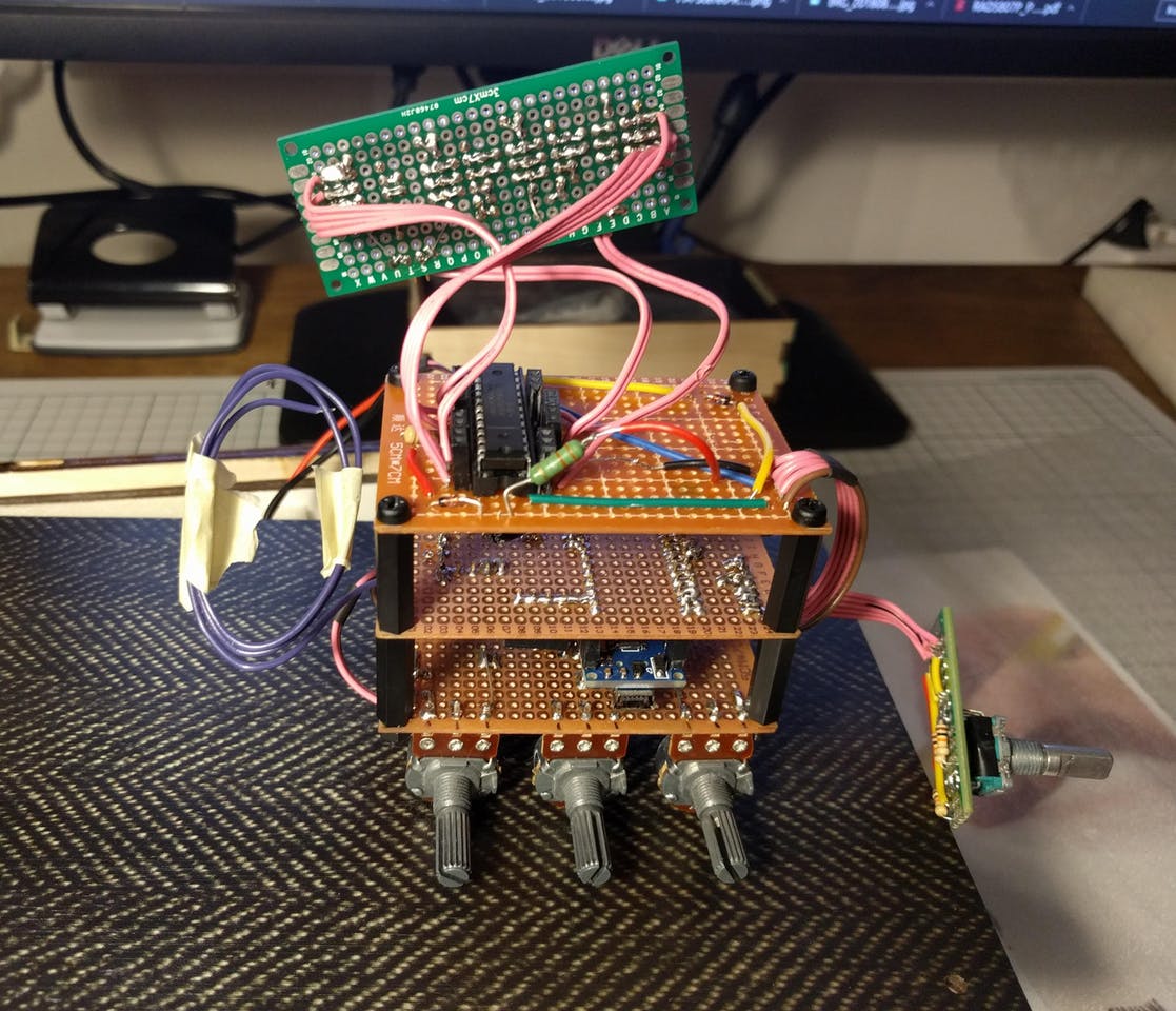
A simple FM radio with a display that shows the frequency and audio amplifier.
My goal was to make simple FM radio with a display that shows the frequency. And manual control over frequency and volume.
2. Hardware
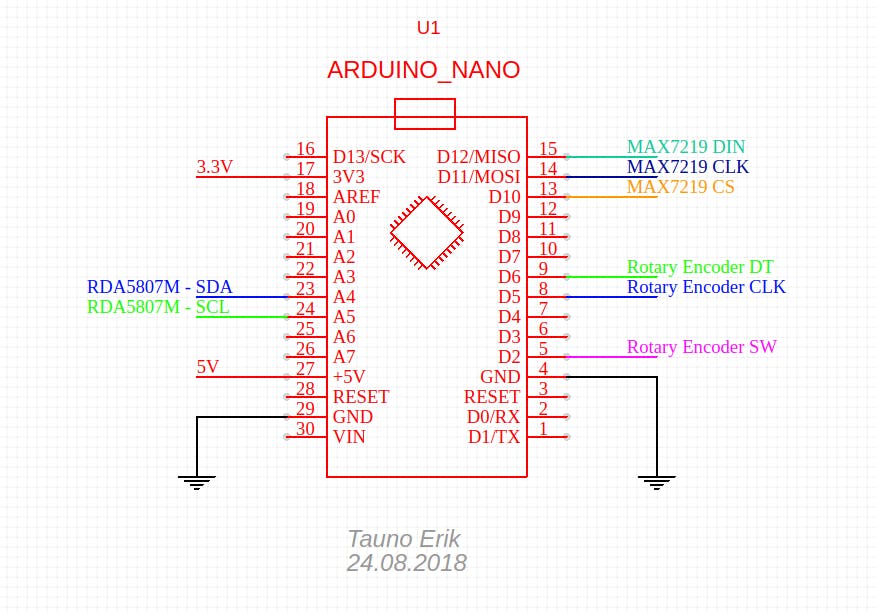
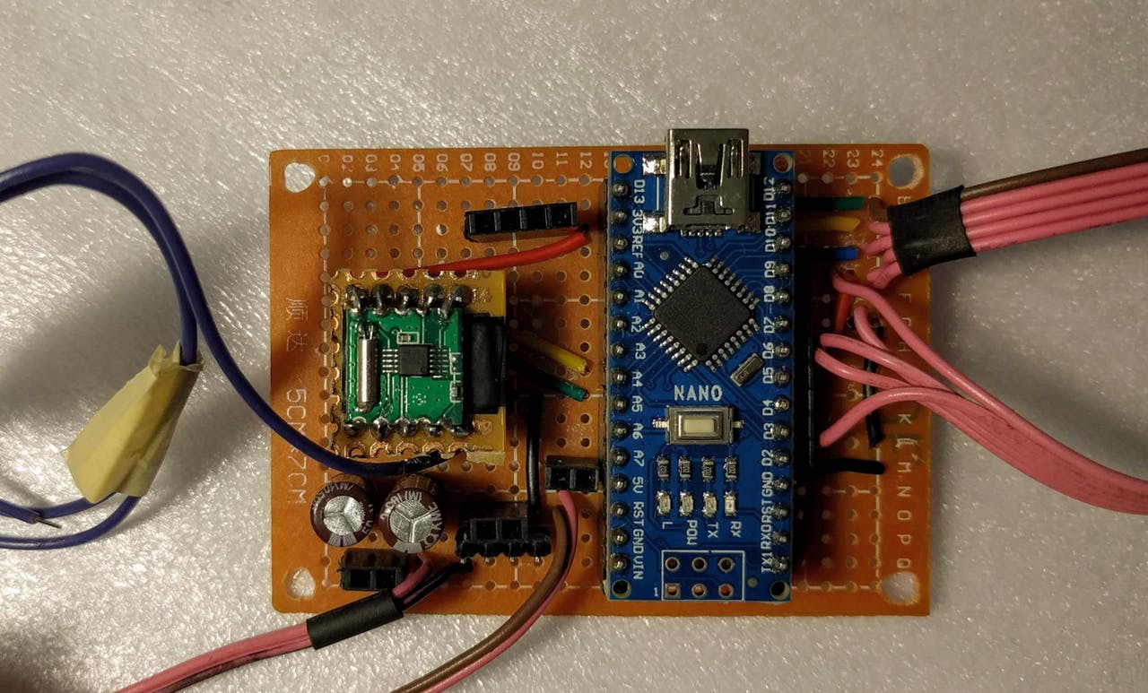
You can use Arduino Uno or Nano:
2.1 RDA5807
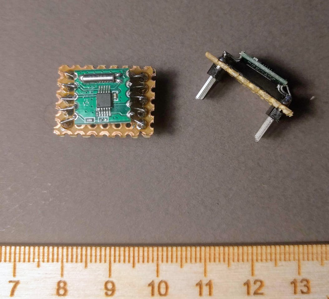
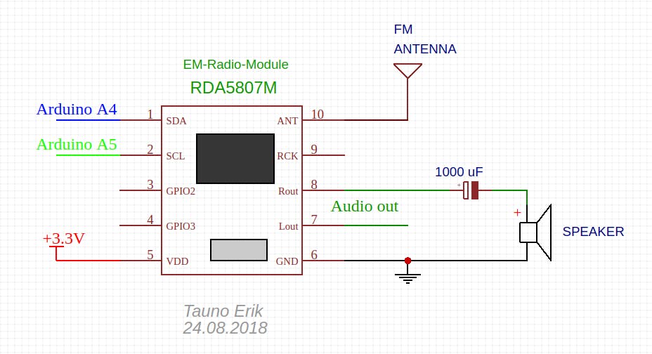
The main component is RDA5807 Sinle-Chip FM Receiver Module. It’s very tiny..So you need to build some kind adapter.
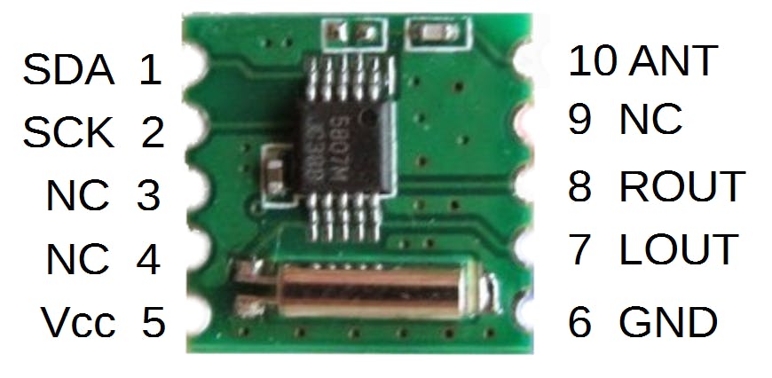
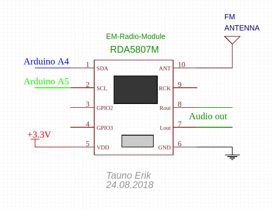
Connect RDA5807 pin 1 (SDA) to Arduino A4 and pin 2 (SCL) to Arduino A5. Pin 5 to 3.3v and pin 6 to Ground. Pin 10 is antenna. 7 is left and 8 is right audio output. The antenna may be just a piece of wire.
You can connect speaker directly to RDA5807:
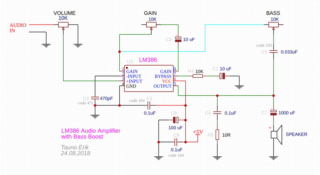
Or connect to amplifier.
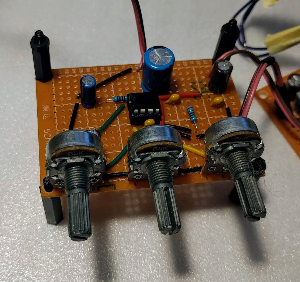
2.2 Amplifier
I used LM386 to make this simple mono audi amplifier
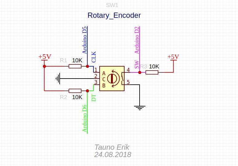
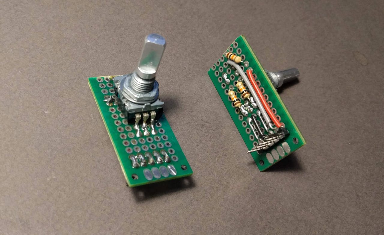
2.3 Rotary Encoder
We use the Rotary Encoder to determine whether we are turning down (left) or up (right) the frequency.
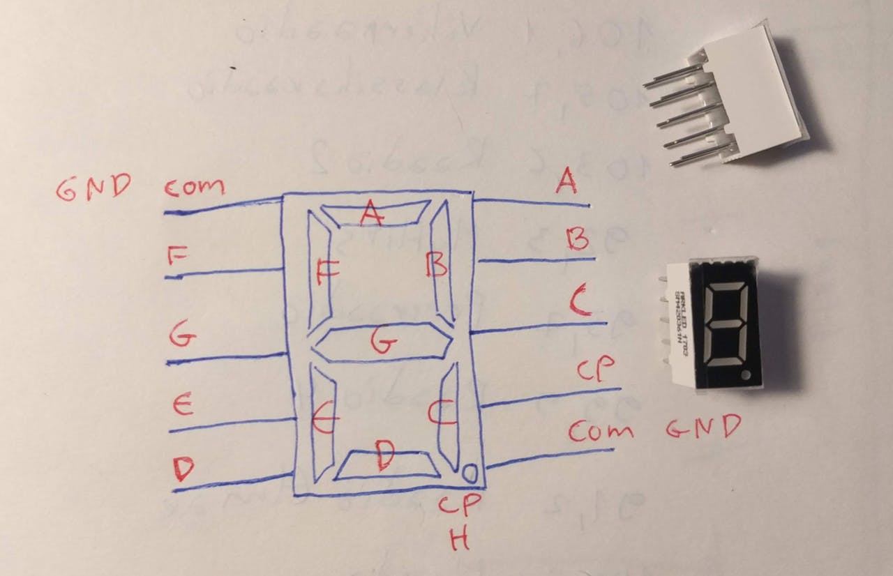
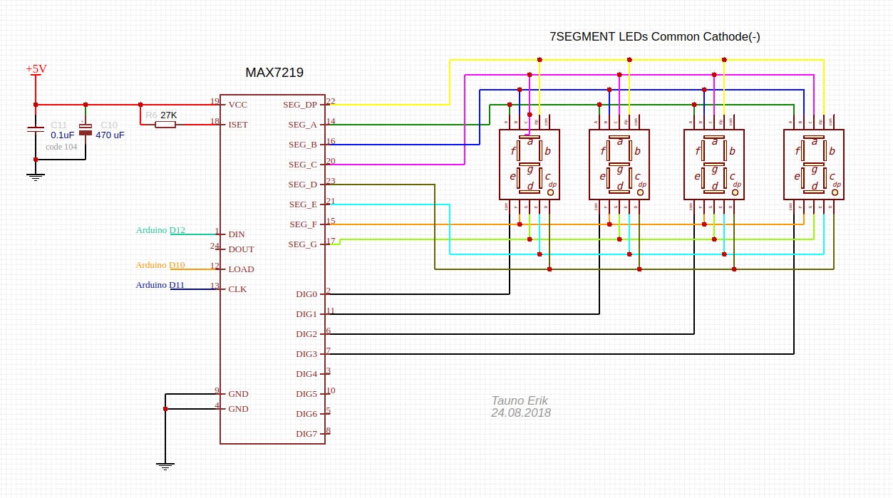
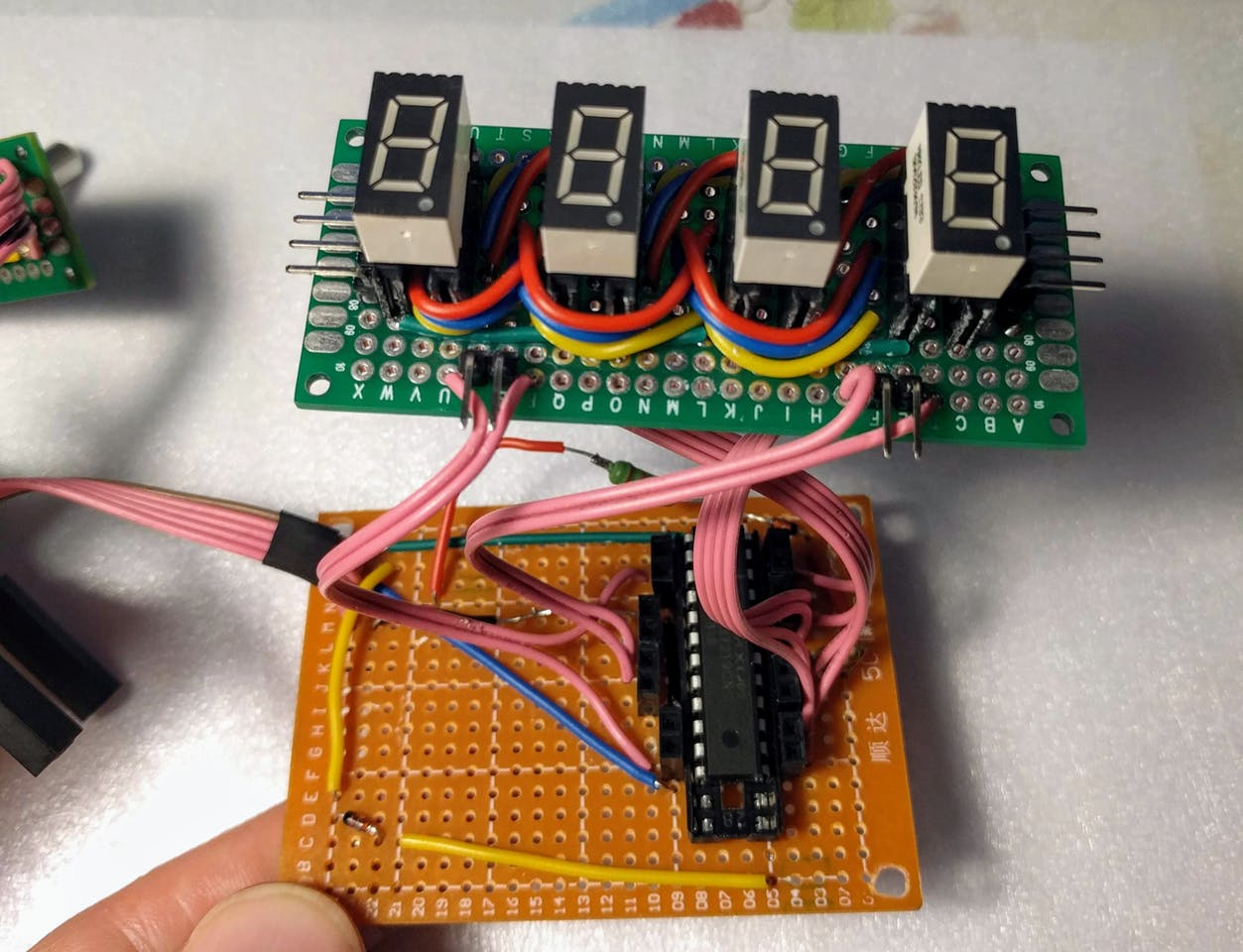
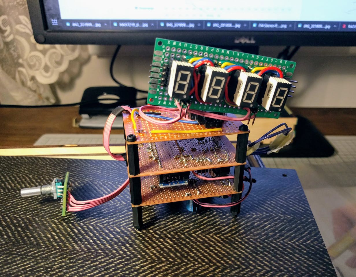
2.4 7-Segment LED Display
It is easier and cheaper to buy readymade 7-segment LED module than to build it yourself.
But it is more fun to make it yourself. Like I did. There is many diffrent coloure and sizes 7-segment LEDs and they may be diffrent. So first test how it works. We need Common Cathode 7-segment LEDs. Mine looks like this:
I use MAX7219 IC to drive LEDs, but it does make a lot of electric noise. What can be heard from the speaker… Thay they that MAX7221 is better.
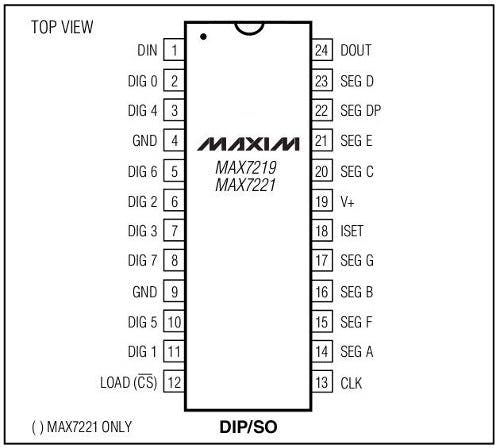
Connect MAX7219 DIN (Data In, leg 1) to Arduino D12, LOAD to D10 and CLK to D11.
3. Software
We use I2C protocol to communicate with RDA5807 Radio module:
#include <Wire.h>Define Arduino pins what we use:
/* MAX7219 LED driver */
#define MAX7219_DIN 12
#define MAX7219_CS  10
#define MAX7219_CLK 11
/* Rotary Encoder */
#define clkPin 5
#define dtPin  6
#define swPin  2
The code how to use RDA5807 I found it here: https://github.com/lucsmall/Arduino-RDA5807M
The channel is default frequensy what radio plays when it boot up.
If Radio frequensy is 106.1 MHz. (106.1 x 10) – 870 = 191
uint16_t channel = 191;Address of the RDA5807 on two wire bus:
#define RDA5807M_ADDRESS 0b0010000 // 0x10See the code here with all coments what it means: https://github.com/lucsmall/Arduino-RDA5807M/blob/master/A20150415RDA5807FMTuner.ino
#define BOOT_CONFIG_LEN 12
#define TUNE_CONFIG_LEN 4
uint8_t boot_config[] = {
 0b11000000,
 0b00000011,
 0b00000000,
 0b00000000,
 0b00001010,
 0b00000000,
 0b10001000,
 0b00001111,
 0b00000000,
 0b00000000,
 0b01000010,
 0b00000010,
};
uint8_t tune_config[] = {
  0b11000000,
  0b00000001,
  (channel >> 2),
  ((channel & 0b11) << 6 ) | 0b00010000
};
void setup()
{
/* Rotary Encoder: */
pinMode(clkPin, INPUT);
pinMode(dtPin, INPUT);
pinMode(swPin, INPUT);
digitalWrite(swPin, HIGH);
/* Conect to RDA5807M FM Tuner: */
Wire.begin(); /* join i2c bus (address optional for master) */
Wire.beginTransmission(RDA5807M_ADDRESS); /* Sending boot configuration (device should reset) */
Wire.write(boot_config, BOOT_CONFIG_LEN); /* Write the boot configuration bytes to the RDA5807M */
Wire.endTransmission();
Wire.beginTransmission(RDA5807M_ADDRESS); /* Tuning to channel */
Wire.write(tune_config, TUNE_CONFIG_LEN); /* Write the tuning configuration bytes to the RDA5807M */
Wire.endTransmission();
// put your setup code here, to run once:
initialise();
output(0x0f, 0x00); //display test register - test mode off
output(0x0c, 0x01); //shutdown register - normal operation
output(0x0b, 0x07); //scan limit register - display digits 0 thru 7
output(0x0a, 0x0f); //intensity register - max brightness
output(0x09, 0xff); //decode mode register - CodeB decode all digits
output(0x08, 0x0c); //digit 7 (leftmost digit) data
output(0x07, 0x0b);
output(0x06, 0x0d);
output(0x05, 0x0e);
output(0x04, 0x08);
output(0x03, 0x07);
output(0x02, 0x06);
output(0x01, 0x05); //digit 0 (rightmost digit) data
}//setup endStart main loop:
void loop()
{
Read Rotary Encoder:
int change = getEncoderTurn();
 if (change > 0){
   channel++;
   myChangeChannel(channel);
   }
 else if(change < 0){
   channel--;
   myChangeChannel(channel);
   }
If you what to read Rotary Encoder Button:
if(digitalRead(swPin) == LOW) //if button pull down
 {
   /* do something */
 }
We calculate every display digit separately:
uint16_t frequency = channel+870;
 uint16_t num1 = (frequency / 1000) % 10;
 uint16_t num2 = (frequency / 100) % 10;
 uint16_t num3 = (frequency / 10) % 10;
 uint16_t num4 = frequency % 10;
Send digits to display:
output(0x01, num1);
 output(0x02, num2);
 output(0x03, num3);
 output(0x04, num4);
}//loop end
Function to read Rotary Encoder turn: left or right. Returns: 1 or -1.
int getEncoderTurn(void)
{
 static int oldA = HIGH; // set the oldA as HIGH
 static int oldB = HIGH; // set the oldB as HIGH
 int result = 0;
 int newA = digitalRead(clkPin);   // read the value of clkPin to newA
 int newB = digitalRead(dtPin);    // read the value of dtPin to newB
 if (newA != oldA || newB != oldB) // if the value of clkPin or the dtPin has changed
 {
   /* something has changed */
   if (oldA == HIGH && newA == LOW)
   {
     result = (oldB * 2 - 1);
     /* Serial.print("Result: ");
        Serial.println(result); */
   }
 }
 oldA = newA;
 oldB = newB;
 return result; // 1 or -1
}
Function to change channel on radio RDA5807. Example: channel = 191
void myChangeChannel(int channel){
  //first write new channel to tune_config massive
  tune_config[2] = (channel >> 2);
  tune_config[3] = ((channel & 0b11) << 6 ) | 0b00010000;
     Wire.begin();
     Wire.beginTransmission(RDA5807M_ADDRESS);
     Wire.write(tune_config, TUNE_CONFIG_LEN);
     Wire.endTransmission();
 }
Function to initialise MAX7219 7-segment LED display
void initialise()
{
 digitalWrite(MAX7219_CS, HIGH);
 pinMode(MAX7219_DIN, OUTPUT);
 pinMode(MAX7219_CS, OUTPUT);
 pinMode(MAX7219_CLK, OUTPUT);
}
Function to send data to MAX7219 7-segment LED display
void output(byte address, byte data)
{
digitalWrite(MAX7219_CS, LOW);
shiftOut(MAX7219_DIN, MAX7219_CLK, MSBFIRST, address);
shiftOut(MAX7219_DIN, MAX7219_CLK, MSBFIRST, data);
digitalWrite(MAX7219_CS, HIGH);
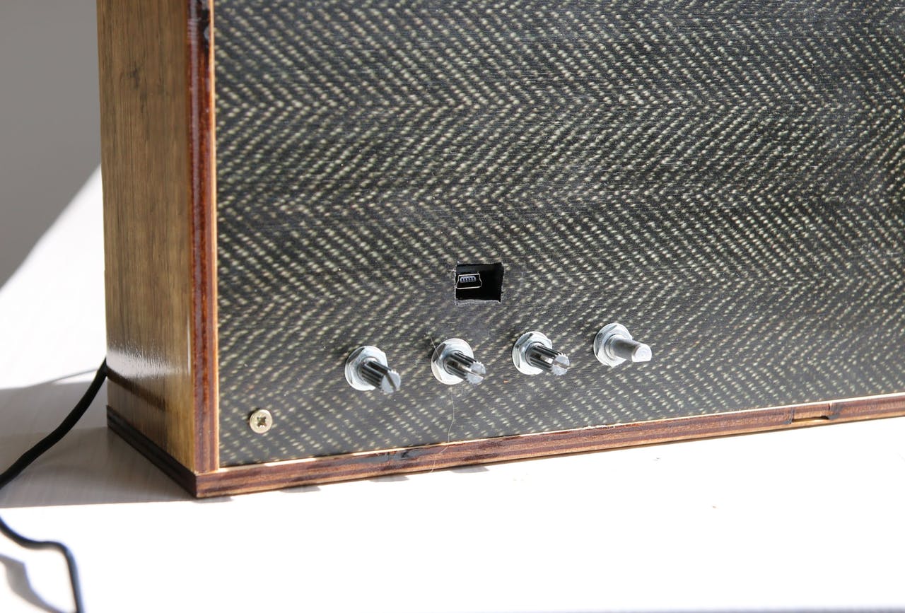
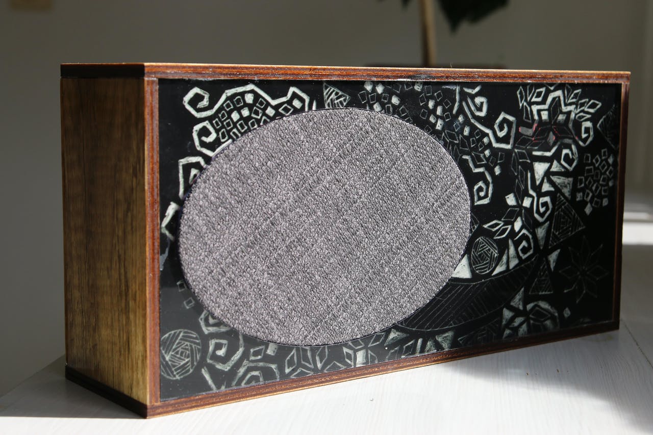
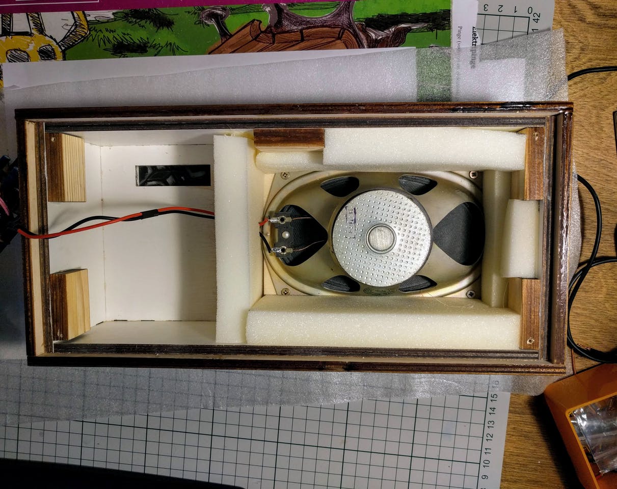
}4. Enclosure
Use your fantasy.

How can I prevent empty noise from empty frequencies on the radio?
If you do not want manually tune the channel. You can use seek up or down function.
I’m also making an fm radio, I have a question. How does the RDA5807 noise canceling work? I don’t want to hear the noise at empty frequencies. Is there a way to prevent it?
Maybe it is helpful to look at this code. There are comments on what different bits will do. https://github.com/lucsmall/Arduino-RDA5807M/blob/master/A20150415RDA5807FMTuner.ino
Coder1448 blog message scroll down page
Coder1448 My messages I constantly asked for help from blog pages
https://tsibrov.blogspot.com/2019/11/rda5807m-part1.html
http://nicuflorica.blogspot.com/2016/07/radio-fm-cu-rda5807-si-arduino.html
https://full-chip.net/arduino-proekty/97-cifrovoy-fm-priemnik-na-arduino-i-module-rda5807-s-graficheskim-displeem-i-funkciey-rds.html
https://s2.solveforum.com/threads/how-can-i-make-noise-canceller-on-rda5807-fm.342589/
https://www.instructables.com/Full-Digital-FM-Receiver-With-Arduino-and-TEA5767/
I’ve been texting all day with no response.
Tauno Erik comment-reply@wordpress.com, 20 Eyl 2022 Sal, 12:31 tarihinde Åunu yazdı:
I entered 8-bit numbers but the noise did not go away
Change bits on tune_config and then
Wire.begin();
Wire.beginTransmission(RDA5807M_ADDRESS);
Wire.write(tune_config, TUNE_CONFIG_LEN);
Wire.endTransmission();
can you send me a complete code, i’m having trouble understanding hexadecimal codes
I just wrote 1 so that all of these features are active and it hasn’t changed. When I make all of them active in the RDA5807 computer program, it works, but I manually enter the hex code, unfortunately it is not active.
i am making a project that when the radio station is turned off the broadcast will automatically switch to noise mode and then it will stop the noise and send me an sms message to the mobile phone that the broadcast is interrupted
Of course, to do this, I’ve been working on it for days to have the soft noise options enabled first.
Tauno Erik comment-reply@wordpress.com, 20 Eyl 2022 Sal, 14:32 tarihinde şunu yazdı:
Hello-
I need an easy way to build an FM frequency display. 7 segment LEDs are fine. This would be for the LO frequency in and the carrier frequency displayed, Namely the display frequency DF=LO frequency-10.7MHZ.
I’m an EE but no software background so a pre-programmed device would be preferable.
Suggestions?
Thanks,
Mark
Hello Tauno. I seem not able to change the volume to say decimal 4. In your codes I presume the volume is at 0b00001111 – this value is decimal 15. I read this at your recommendation to other readers at GitHub. I tried to change the value to 0b00000100 but the volume is still the same. Can you please recommend as I am a beginner.
I had the same problems with this module. And I didn’t figure out where was the problem.