Starting point how to use wireless radio frequency transmitter & receiver modules.
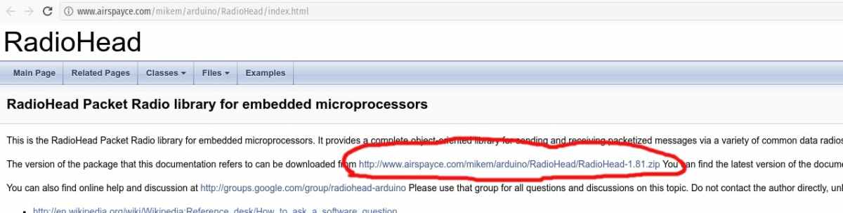
1. Download RadioHead library:
http://www.airspayce.com/mikem/arduino/RadioHead/index.html
http://www.airspayce.com/mikem/arduino/RadioHead/RadioHead-1.81.zip
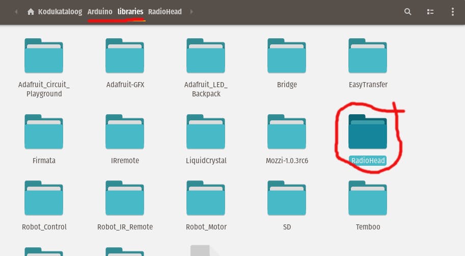
Unzip and copy it into Arduino library folder:
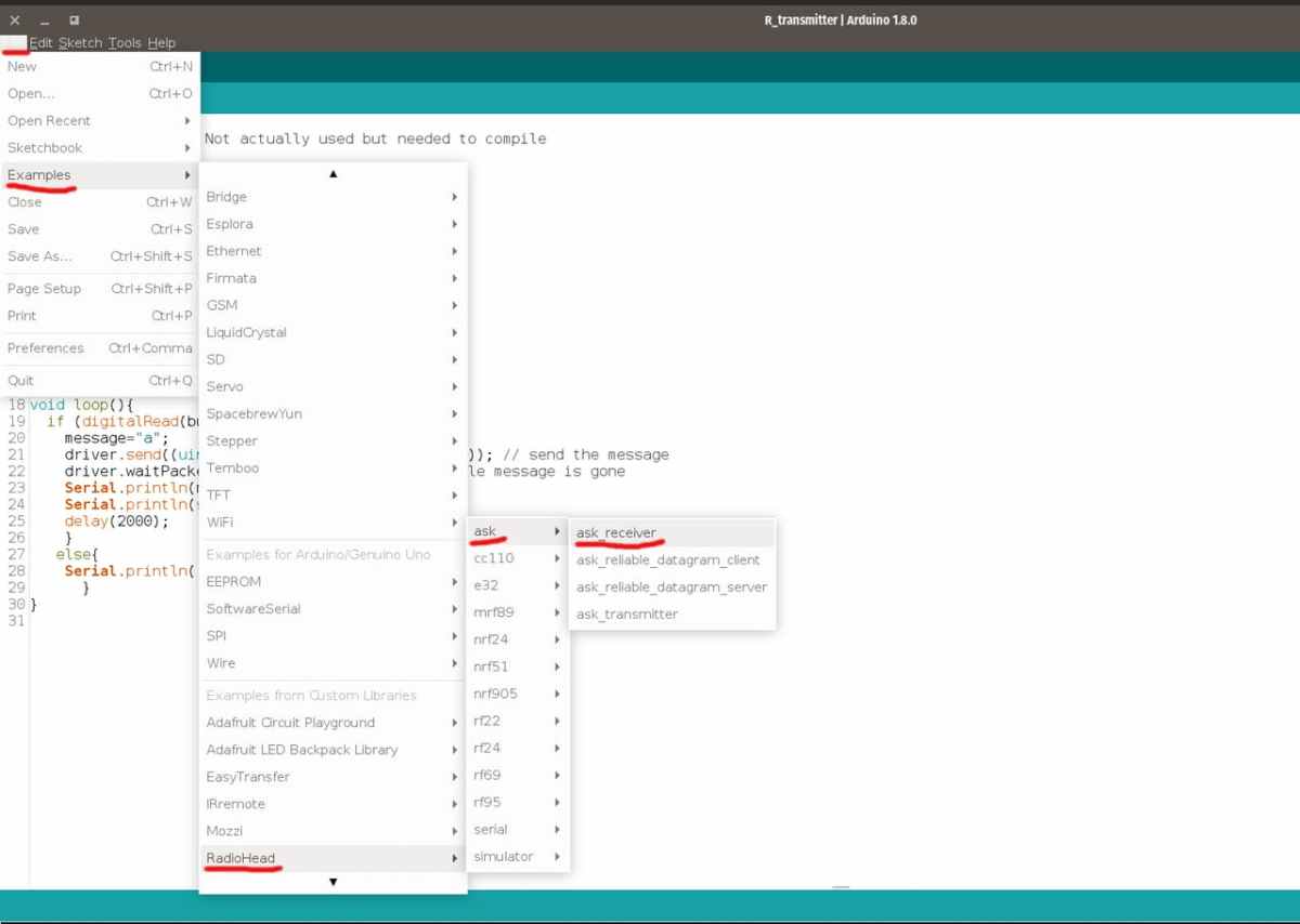
Now you should to see RadioHead example code:
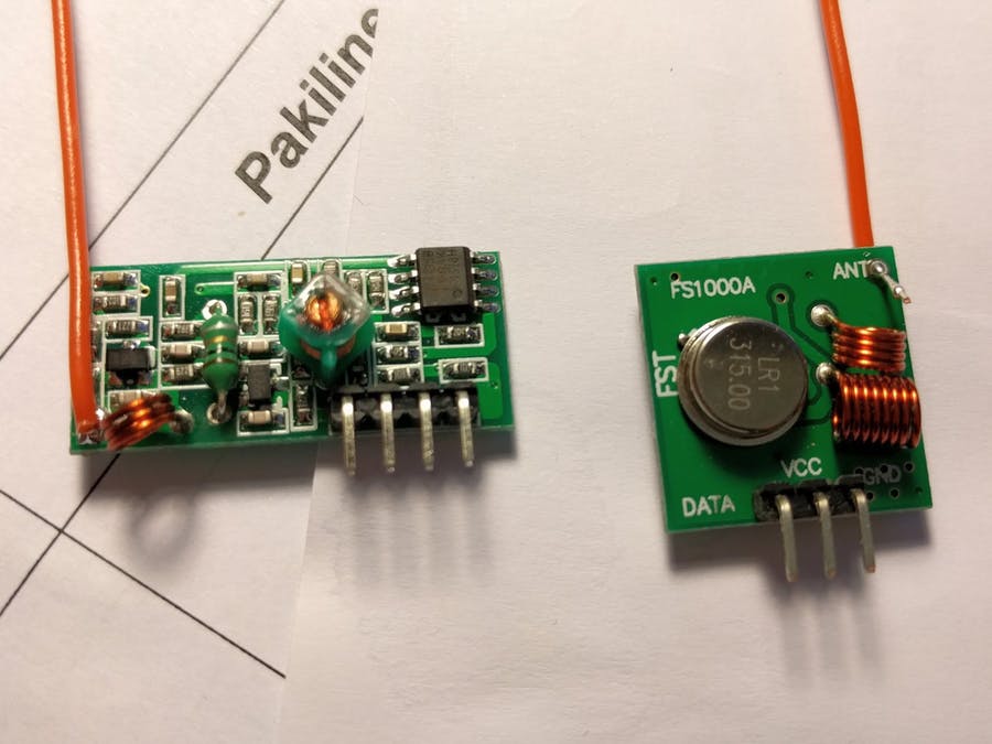
2. Transmitter module:
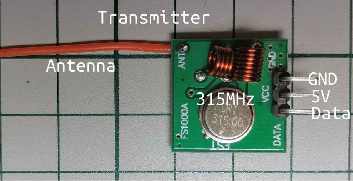
Antenna lenght depens do you have 315, 330 or 433 MHz module. Best is to use the antenna of 1/4 wavelength (or 1/2, 1/8).
Online calculator: http://www.onlineconversion.com/frequency_wavelength.htm
- 315MHz wavelenght is 0.95 m, 1/4 = 23.75 cm
- 330MHz wavelenght is 0.91 m, 1/4 = 22.75 cm
- 433MHz wavelenght is 0.69 m, 1/4 = 17.25 cm
Youse single core wire. Antennas should be on same orientations. Both of them horizontal or vertical.
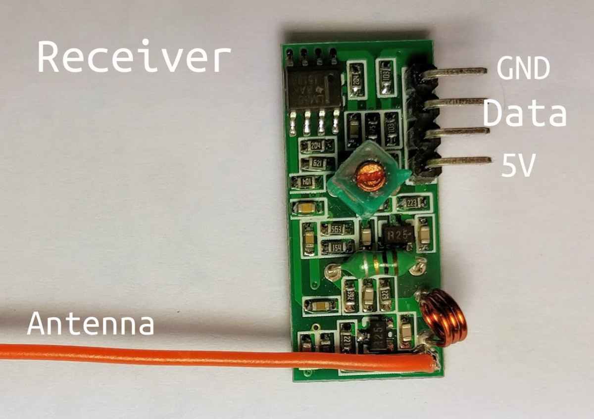
3. Receiver module
4. Transmitter test circuit
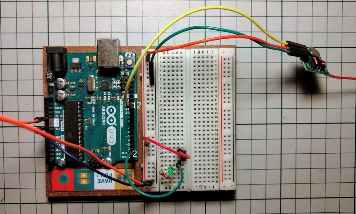
Transmitter Test Code:
#include
#include
const char *message = "";
int button = 2;
RH_ASK driver;
void setup() {
 Serial.begin(9600); // Debugging only
 if (!driver.init()){
   Serial.println("init of receiver failed");
 }
 pinMode(button,INPUT);
}
void loop(){
 if (digitalRead(button) == HIGH){
   message="a";
   driver.send((uint8_t *)message, strlen(message)); // send the message
   driver.waitPacketSent(); // Wait until the whole message is gone
   Serial.println(message);
   Serial.println(strlen(message));
   delay(2000);
   }
  else{
   //Serial.println("Low");
     }
}
5. Receiver test circuit
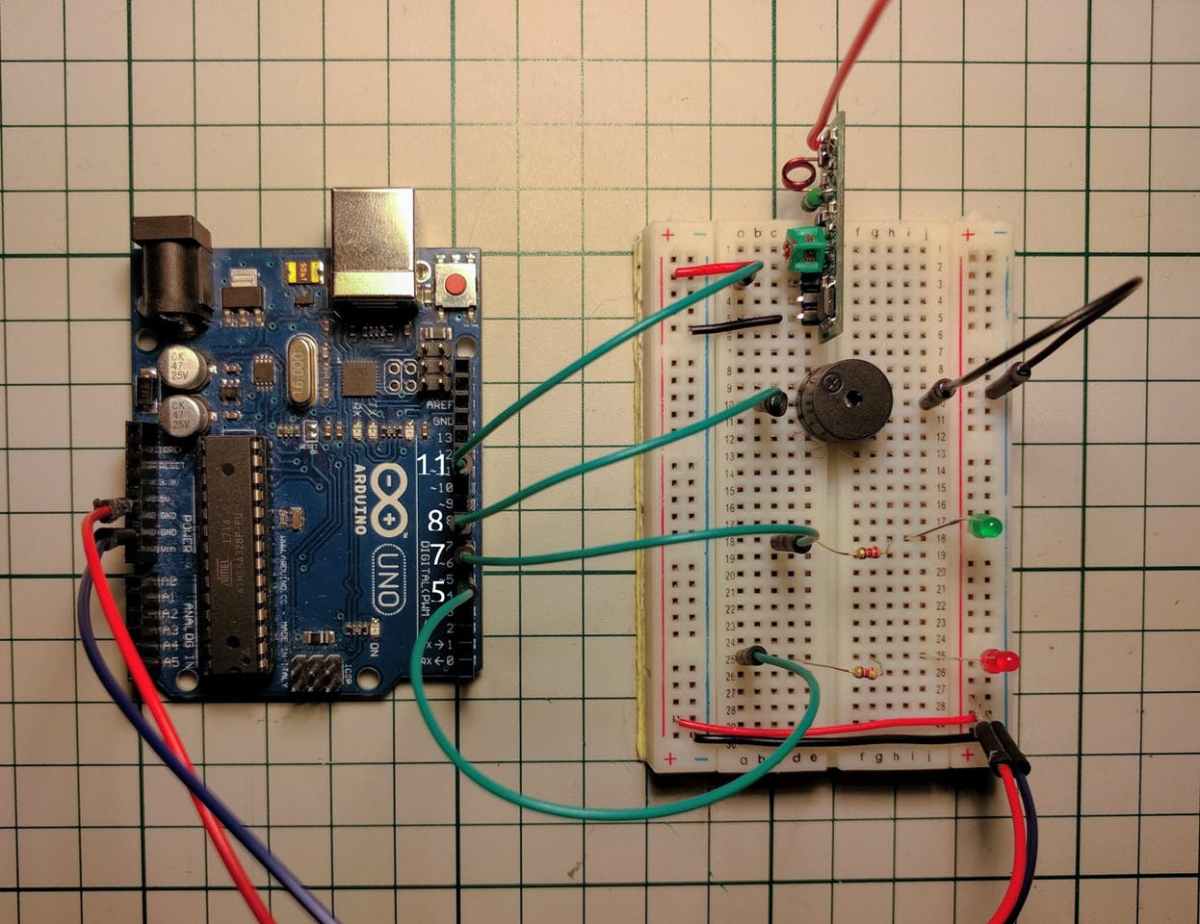
Receiver Test Code:
#include <RH_ASK.h>
#include <SPI.h>
RH_ASK driver; //pin 12
// RH_ASK driver(2000, 2, 4, 5); // ESP8266: do not use pin 11
int ledPassive = 5; //standby light
int ledActive = 7; //green LED's
void setup()
{
 pinMode(ledPassive,OUTPUT);
 pinMode(ledActive,OUTPUT);
 Serial.begin(9600); // Debugging only
 if (!driver.init())
 Serial.println("init of receiver failed");
}
void loop()
{
 digitalWrite(ledPassive,HIGH);
 noTone(8);
 digitalWrite(ledActive,LOW);
 uint8_t buf[RH_ASK_MAX_MESSAGE_LEN];
 uint8_t buflen = sizeof(buf);
 if (driver.recv(buf, &buflen)) { // if message received
   for(int i=0;i<sizeof(buf);i++){
     Serial.print(char(buf[i])); //test display output
   }
   if(buf[0]=='a'){ // and if the first letter in message array is X
     digitalWrite(ledPassive,LOW);
     for(int i=0;i<10;i++){ // loop alternates between LED and buzzer
       digitalWrite(ledActive,HIGH);
       tone(8, 262); //pin 8
       delay(100);
     }
   }
    else if(buf[0]!='a'){
     digitalWrite(ledPassive,HIGH);
     noTone(8);
    }
   }
}
And the result:
Originally published: https://www.hackster.io/taunoerik/radio-frequency-transmitter-receiver-module-with-arduino-af01e4
