ADC (Analog-to-Digital Converter): Converts an analog signal (such as a voltage) into a digital value that can be processed by a microcontroller. The conversion process typically involves sampling the analog signal at a specific rate and quantizing the signal to produce a digital representation.
CH32V003 ADC has a 10-bit resolution. Values 0-1023.
DMA (Direct Memory Access): This is a feature that allows the transfer of data directly to or from memory without involving the CPU. The DMA controller can move data between memory and peripherals autonomously, freeing the CPU to perform other tasks and increasing the efficiency of data transfers.
When combined, ADC DMA refers to a setup where the ADC performs analog-to-digital conversions, and the resulting digital data is transferred directly to memory using DMA.
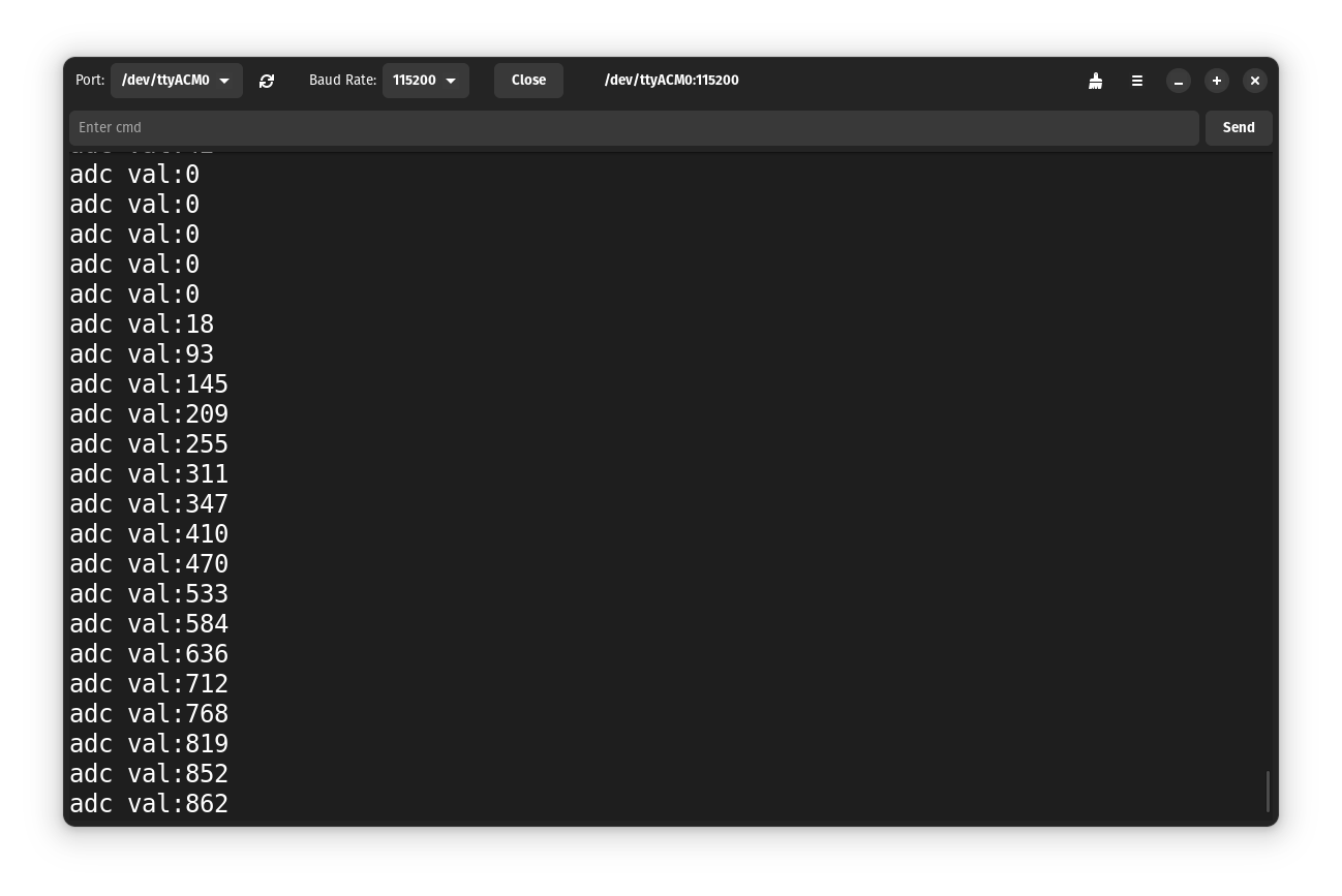
I am using Embeetle IDE for programming and Tauno Monitor for Serial Monitor.

I use my custom-made CH32V003 development board. However, the code should work on all boards that use this MCU. It has 8 ADC channels (Pins). We can not use ADC channels 0 and 1 if the external crystal is connected, like on my board.
My test setup:

This is my main.c file.
/*********************************************************************
 * File Name          : main.c
 * Board              : ch32v003
 * Date               : 13.07.2024
 * Description        : ADC DMA example
**********************************************************************/

#include "debug.h"

/* Global Variable */
u16 TxBuf[10];
// Pin: PA2 - channel 0 can not be used if the external crystal is connected
//      PA1 - channel 1 can not be used if the external crystal is connected
//      PC4 - channel 2
//      PD2 - channel 3
//      PD3 - channel 4
//      PD5 - channel 5
//      PD6 - channel 6
//      PD4 - channel 7
u8 channel = 7;

/*********************************************************************
 * @fn      ADC_Init
 *
 * @brief   Initializes ADC collection.
 *
 * @param   channel - ADC channel.
 *
 * @return  none
 */
void tauno_ADC_init(u8 channel)
{
  ADC_InitTypeDef  ADC_InitStructure = {0};
  GPIO_InitTypeDef GPIO_InitStructure = {0};

  switch (channel) {
    case 0:  // PA2
    case 1:  // PA1
      RCC_APB2PeriphClockCmd(RCC_APB2Periph_GPIOA, ENABLE);
      break;
    case 2:  // PC4
      RCC_APB2PeriphClockCmd(RCC_APB2Periph_GPIOC, ENABLE);
      break;
    case 3:  // PD2
    case 4:  // PD3
    case 5:  // PD5
    case 6:  // PD6
    case 7:  // PD4
      RCC_APB2PeriphClockCmd(RCC_APB2Periph_GPIOD, ENABLE);
      break;
    default:
      break;
  }

  RCC_APB2PeriphClockCmd(RCC_APB2Periph_ADC1, ENABLE);
  RCC_ADCCLKConfig(RCC_PCLK2_Div8);

  switch (channel) {
    case 0:  // PA2
      GPIO_InitStructure.GPIO_Pin = GPIO_Pin_2;
      break;
    case 1:  // PA1
      GPIO_InitStructure.GPIO_Pin = GPIO_Pin_1;
      break;
    case 2:  // PC4
      GPIO_InitStructure.GPIO_Pin = GPIO_Pin_4;
      break;
    case 3:  // PD2
      GPIO_InitStructure.GPIO_Pin = GPIO_Pin_2;
      break;
    case 4:  // PD3
      GPIO_InitStructure.GPIO_Pin = GPIO_Pin_3;
      break;
    case 5:  // PD5
      GPIO_InitStructure.GPIO_Pin = GPIO_Pin_5;
      break;
    case 6:  // PD6
      GPIO_InitStructure.GPIO_Pin = GPIO_Pin_6;
      break;
    case 7:  // PD4
      GPIO_InitStructure.GPIO_Pin = GPIO_Pin_4;
      break;
    default:
      break;
  }

  GPIO_InitStructure.GPIO_Mode = GPIO_Mode_AIN;

  switch (channel) {
    case 0:  // PA2
    case 1:  // PA1
      GPIO_Init(GPIOA, &GPIO_InitStructure);
      break;
    case 2:  // PC4
      GPIO_Init(GPIOC, &GPIO_InitStructure);
      break;
    case 3:  // PD2
    case 4:  // PD3
    case 5:  // PD5
    case 6:  // PD6
    case 7:  // PD4
      GPIO_Init(GPIOD, &GPIO_InitStructure);
      break;
    default:
      break;
  }

  ADC_DeInit(ADC1);
  ADC_InitStructure.ADC_Mode = ADC_Mode_Independent;
  ADC_InitStructure.ADC_ScanConvMode = DISABLE;
  ADC_InitStructure.ADC_ContinuousConvMode = ENABLE;
  ADC_InitStructure.ADC_ExternalTrigConv = ADC_ExternalTrigConv_None;
  ADC_InitStructure.ADC_DataAlign = ADC_DataAlign_Right;
  ADC_InitStructure.ADC_NbrOfChannel = 1;
  ADC_Init(ADC1, &ADC_InitStructure);

  ADC_Calibration_Vol(ADC1, ADC_CALVOL_50PERCENT);
  ADC_DMACmd(ADC1, ENABLE);
  ADC_Cmd(ADC1, ENABLE);

  ADC_ResetCalibration(ADC1);
  while(ADC_GetResetCalibrationStatus(ADC1));
  ADC_StartCalibration(ADC1);
  while(ADC_GetCalibrationStatus(ADC1));

  //s16 Calibrattion_Val = Get_CalibrationValue(ADC1); ????
}

/*********************************************************************
 * @fn      Get_ADC_Val
 *
 * @brief   Returns ADCx conversion result data.
 *
 * @param   ch - ADC channel.
 *            ADC_Channel_0 - ADC Channel0 selected.
 *            ADC_Channel_1 - ADC Channel1 selected.
 *            ADC_Channel_2 - ADC Channel2 selected.
 *            ADC_Channel_3 - ADC Channel3 selected.
 *            ADC_Channel_4 - ADC Channel4 selected.
 *            ADC_Channel_5 - ADC Channel5 selected.
 *            ADC_Channel_6 - ADC Channel6 selected.
 *            ADC_Channel_7 - ADC Channel7 selected.
 *            ADC_Channel_8 - ADC Channel8 selected.
 *            ADC_Channel_9 - ADC Channel9 selected.
 *
 * @return  val
 */
u16 Get_ADC_Val(u8 channel)
{
  u16 val;

  ADC_RegularChannelConfig(ADC1, channel, 1, ADC_SampleTime_241Cycles);
  ADC_SoftwareStartConvCmd(ADC1, ENABLE);

  while(!ADC_GetFlagStatus(ADC1, ADC_FLAG_EOC));
  val = ADC_GetConversionValue(ADC1);

  return val;
}

/*
 * https://github.com/Community-PIO-CH32V/platform-ch32v/blob/develop/examples/adc-cpu-temp-none-os/src/main.c
 */
u16 Get_ADC_Average(u8 ch, u8 times)
{
  u32 temp_val = 0;
  u8 t;
  u16 val;

  for (t = 0; t < times; t++)
  {
    temp_val += Get_ADC_Val(ch);
    Delay_Ms(5);
  }

  val = temp_val / times;

  return val;
}

/*********************************************************************
 * @fn      DMA_Tx_Init
 *
 * @brief   Initializes the DMAy Channelx configuration.
 *
 * @param   DMA_CHx - x can be 1 to 7.
 *          ppadr - Peripheral base address.
 *          memadr - Memory base address.
 *          bufsize - DMA channel buffer size.
 *
 * @return  none
 */
void DMA_Tx_Init(DMA_Channel_TypeDef *DMA_CHx, u32 ppadr, u32 memadr, u16 bufsize)
{
    DMA_InitTypeDef DMA_InitStructure = {0};

    RCC_AHBPeriphClockCmd(RCC_AHBPeriph_DMA1, ENABLE);

    DMA_DeInit(DMA_CHx);
    DMA_InitStructure.DMA_PeripheralBaseAddr = ppadr;
    DMA_InitStructure.DMA_MemoryBaseAddr = memadr;
    DMA_InitStructure.DMA_DIR = DMA_DIR_PeripheralSRC;
    DMA_InitStructure.DMA_BufferSize = bufsize;
    DMA_InitStructure.DMA_PeripheralInc = DMA_PeripheralInc_Disable;
    DMA_InitStructure.DMA_MemoryInc = DMA_MemoryInc_Enable;
    DMA_InitStructure.DMA_PeripheralDataSize = DMA_PeripheralDataSize_HalfWord;
    DMA_InitStructure.DMA_MemoryDataSize = DMA_MemoryDataSize_HalfWord;
    DMA_InitStructure.DMA_Mode = DMA_Mode_Normal;
    DMA_InitStructure.DMA_Priority = DMA_Priority_VeryHigh;
    DMA_InitStructure.DMA_M2M = DMA_M2M_Disable;
    DMA_Init(DMA_CHx, &DMA_InitStructure);
}

/*********************************************************************
 * @fn      main
 *
 * @brief   Main program.
 *
 * @return  none
 */
int main(void) {
  u16 adc_val;  // 0-1023
  u16 i;

  Delay_Init();
  USART_Printf_Init(115200);
  Delay_Ms(3000);  // Give serial monitor time to open
  printf("SystemClk:%d\r\n", (unsigned)SystemCoreClock);
  printf("DeviceID: %08x\r\n", (unsigned)DBGMCU_GetDEVID());

  tauno_ADC_init(channel);

  DMA_Tx_Init(DMA1_Channel1, (u32)&ADC1->RDATAR, (u32)TxBuf, 10);
  DMA_Cmd(DMA1_Channel1, ENABLE);

  ADC_RegularChannelConfig(ADC1, ADC_Channel_2, 1, ADC_SampleTime_241Cycles);
  ADC_SoftwareStartConvCmd(ADC1, ENABLE);
  Delay_Ms(50);
  ADC_SoftwareStartConvCmd(ADC1, DISABLE);

  for (i = 0; i < 10; i++) {
    printf("%04d\r\n", TxBuf[i]);
    Delay_Ms(10);
  }

  while (1) {
    adc_val = Get_ADC_Val(channel);
    printf("adc val:%d\r\n", adc_val);
    Delay_Ms(100);
  }
  return 0;
}
