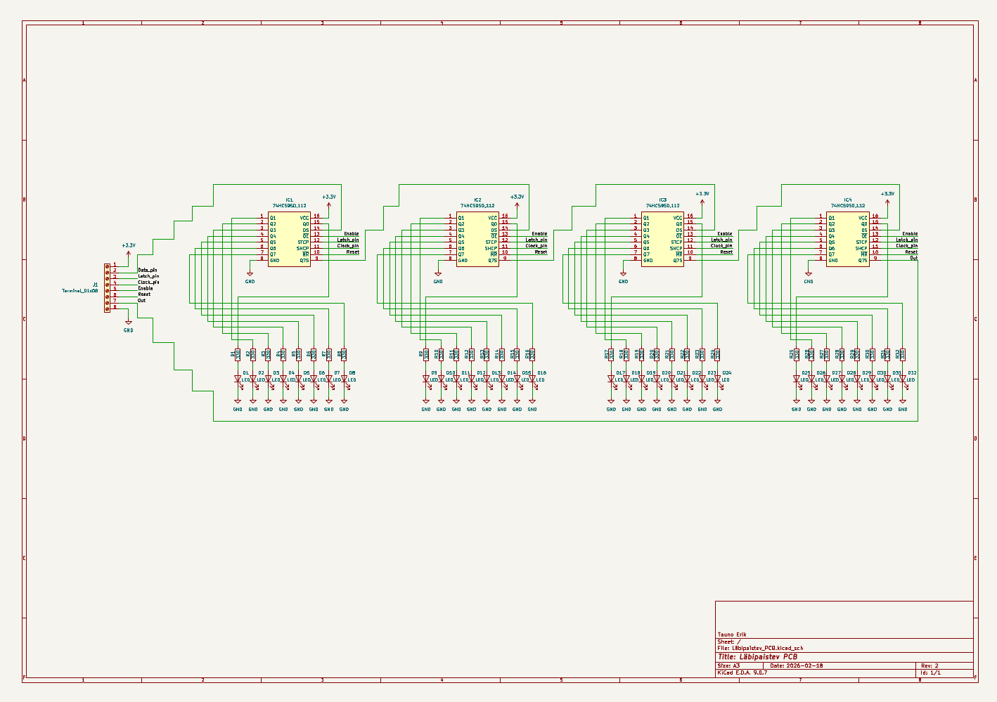
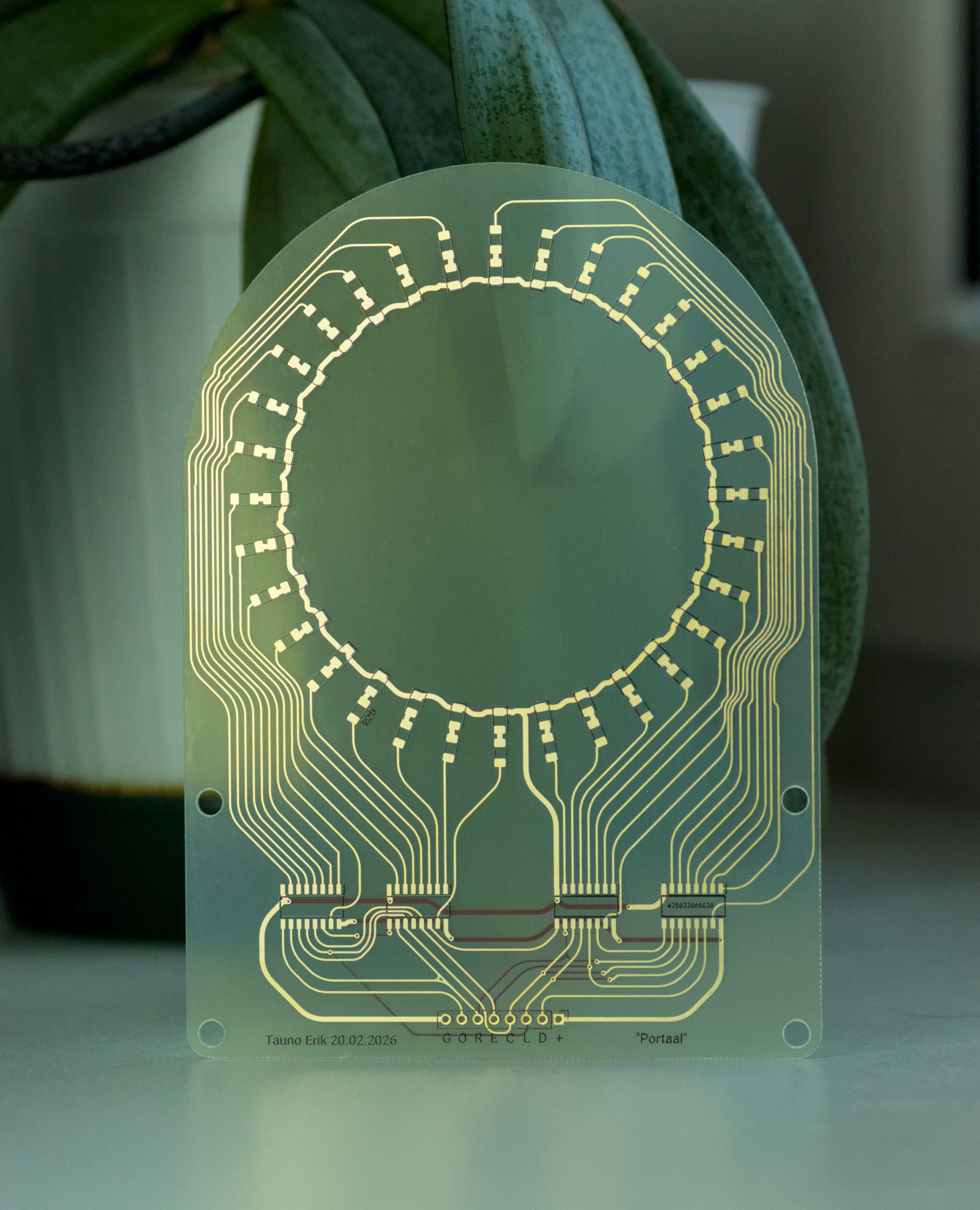
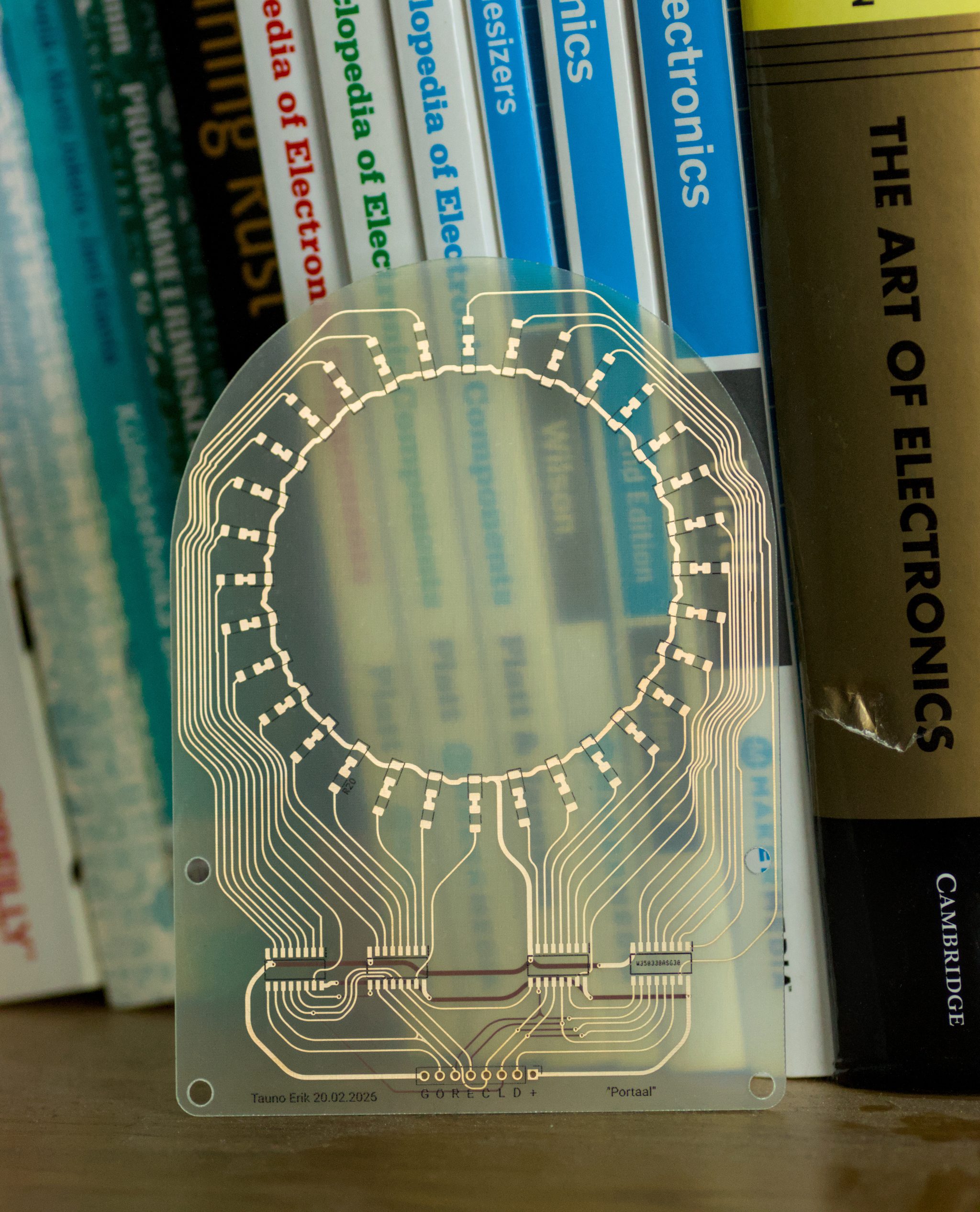
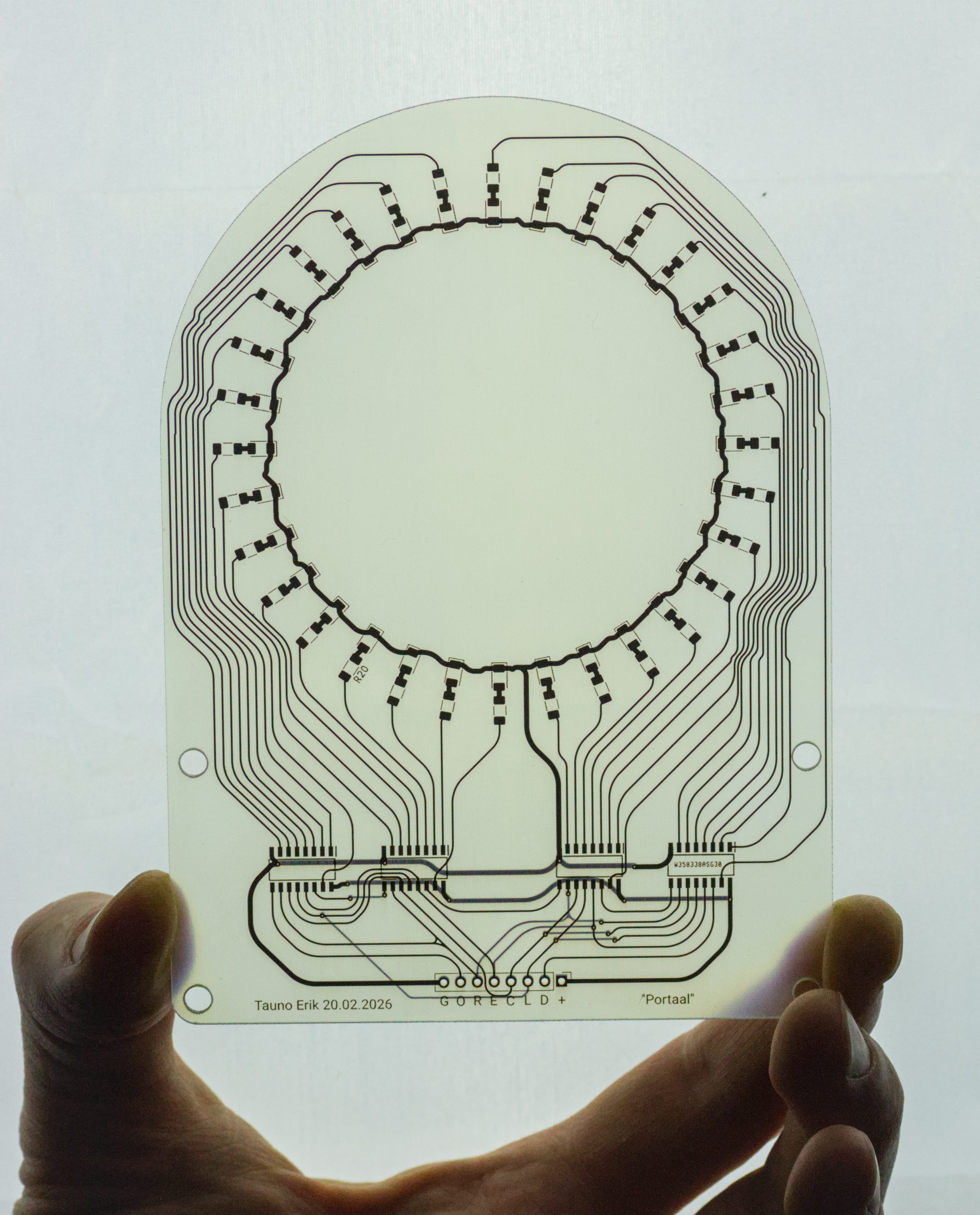
This was made by PCBWay. I designed it in KiCad. It’s basically four shift registers and LEDs. Since it was my first time seeing a transparent PCB, I designed it to explore how it could be used. It’s not transparent like glass. It’s more like translucent and diffuses light. One advantage is that you can see all the tracks.
Mine is without a solder mask. But you can select a transparent solder mask, which is under Advanced PCB.
Pässu and I first look into it:
Test code
This is a test code that uses the CH32V003 microcontroller and MounRiver Studio 2. It shifts round a 1-bit in a 32-bit register to light up the corresponding LED.
#include "debug.h"

// Define our pins on Port C
#define DATA_PIN  GPIO_Pin_0
#define CLOCK_PIN GPIO_Pin_1
#define LATCH_PIN GPIO_Pin_2
#define GPIO_PORT GPIOC


/* Global Variable */
vu8 val;

// Global tick counter
volatile uint32_t global_ms = 0;

/*********************************************************************
 * @fn      USARTx_CFG
 *
 * @brief   Initializes the USART2 & USART3 peripheral.
 *
 * @return  none
 */
void USARTx_CFG(void)
{
    GPIO_InitTypeDef  GPIO_InitStructure = {0};
    USART_InitTypeDef USART_InitStructure = {0};

    RCC_APB2PeriphClockCmd(RCC_APB2Periph_GPIOD | RCC_APB2Periph_USART1, ENABLE);

    /* USART1 TX-->D.5   RX-->D.6 */
    GPIO_InitStructure.GPIO_Pin = GPIO_Pin_5;
    GPIO_InitStructure.GPIO_Speed = GPIO_Speed_30MHz;
    GPIO_InitStructure.GPIO_Mode = GPIO_Mode_AF_PP;
    GPIO_Init(GPIOD, &GPIO_InitStructure);
    GPIO_InitStructure.GPIO_Pin = GPIO_Pin_6;
    GPIO_InitStructure.GPIO_Mode = GPIO_Mode_IN_FLOATING;
    GPIO_Init(GPIOD, &GPIO_InitStructure);

    USART_InitStructure.USART_BaudRate = 115200;
    USART_InitStructure.USART_WordLength = USART_WordLength_8b;
    USART_InitStructure.USART_StopBits = USART_StopBits_1;
    USART_InitStructure.USART_Parity = USART_Parity_No;
    USART_InitStructure.USART_HardwareFlowControl = USART_HardwareFlowControl_None;
    USART_InitStructure.USART_Mode = USART_Mode_Tx | USART_Mode_Rx;

    USART_Init(USART1, &USART_InitStructure);
    USART_Cmd(USART1, ENABLE);
}

// Update the global tick every 1ms
void SysTick_Handler(void) __attribute__((interrupt("WCH-Interrupt-fast")));
void SysTick_Handler(void) {
    global_ms++;
    SysTick->SR = 0; // Clear interrupt flag
}

void SysTick_Init(void) {
    // SystemCoreClock is usually 48MHz
    // Set reload to trigger every 1ms
    SysTick->CMP = SystemCoreClock / 1000;
    SysTick->CNT = 0;
    SysTick->CTLR = 0x0F; // Enable interrupt, enable counter, HCLK as clock
    NVIC_EnableIRQ(SysTick_IRQn);
}

void SPI_1_config(void) {
    GPIO_InitTypeDef GPIO_InitStructure = {0};
    SPI_InitTypeDef  SPI_InitStructure = {0};

    RCC_APB2PeriphClockCmd(RCC_APB2Periph_GPIOC | RCC_APB2Periph_SPI1, ENABLE);

    // PC5 (SCK) & PC6 (MOSI) as Alternate Function Push-Pull
    GPIO_InitStructure.GPIO_Pin = GPIO_Pin_5 | GPIO_Pin_6;
    GPIO_InitStructure.GPIO_Mode = GPIO_Mode_AF_PP;
    GPIO_InitStructure.GPIO_Speed = GPIO_Speed_50MHz;
    GPIO_Init(GPIOC, &GPIO_InitStructure);

    // PC1 (Latch) as standard Output
    GPIO_InitStructure.GPIO_Pin = GPIO_Pin_1;
    GPIO_InitStructure.GPIO_Mode = GPIO_Mode_Out_PP;
    GPIO_Init(GPIOC, &GPIO_InitStructure);

    SPI_InitStructure.SPI_Direction = SPI_Direction_1Line_Tx;
    SPI_InitStructure.SPI_Mode = SPI_Mode_Master;
    SPI_InitStructure.SPI_DataSize = SPI_DataSize_8b;
    SPI_InitStructure.SPI_CPOL = SPI_CPOL_Low;
    SPI_InitStructure.SPI_CPHA = SPI_CPHA_1Edge;
    SPI_InitStructure.SPI_NSS = SPI_NSS_Soft;
    SPI_InitStructure.SPI_BaudRatePrescaler = SPI_BaudRatePrescaler_8; // 3MHz
    SPI_InitStructure.SPI_FirstBit = SPI_FirstBit_MSB;
    SPI_Init(SPI1, &SPI_InitStructure);

    SPI_Cmd(SPI1, ENABLE);
}

void SPI_send_data(uint32_t data) {
    GPIO_WriteBit(GPIOC, GPIO_Pin_1, Bit_RESET); // Latch LOW

    // Send 4 bytes (32 bits)
    for(int i = 3; i >= 0; i--) {
        while(SPI_I2S_GetFlagStatus(SPI1, SPI_I2S_FLAG_TXE) == RESET);
        SPI_I2S_SendData(SPI1, (uint8_t)(data >> (i * 8)));
    }

    // Wait for last byte to finish
    while(SPI_I2S_GetFlagStatus(SPI1, SPI_I2S_FLAG_BSY) == SET);
    GPIO_WriteBit(GPIOC, GPIO_Pin_1, Bit_SET); // Latch HIGH
}

/*********************************************************************
 * @fn      main
 *
 * @brief   Main program.
 *
 * @return  none
 */
int main(void)
{
    NVIC_PriorityGroupConfig(NVIC_PriorityGroup_1); // 2?
    SystemCoreClockUpdate();
    Delay_Init();

    SPI_1_config();
    SysTick_Init();

#if (SDI_PRINT == SDI_PR_OPEN)
    SDI_Printf_Enable();
#else
    USART_Printf_Init(115200);
#endif
    printf("SystemClk:%d\r\n",SystemCoreClock);
    printf( "ChipID:%08x\r\n", DBGMCU_GetCHIPID() );

    USARTx_CFG();


    uint32_t data = 0x01;
    uint32_t last_update_time = 0;
    const uint32_t interval = 15; // 100ms update rate

    while(1)
    {
        if (global_ms - last_update_time >= interval) {
            last_update_time = global_ms;

            SPI_send_data(data);

            // Rotate bits for a "running light" effect
            data = (data << 1);
            if (data == 0) {
                data = 0x01;
            }
        }
    } // while end
}
