These are notes to myself. I fill them in over time as I work through the material.
I recently bought two Freenove ESP32-S3-Wroom boards. One thing you immediately notice is that they have two USB-C ports. One is USB-UART and the other is USB-OTG. USB-UART is like the regular USB on this kind of board. To program them and Serial.print() and etc. This USB acts only as a device. USB-UART uses an external USB-to-serial chip. This is on all older boards.
USB-OTG is something new to me. OTG means On The Go. The USB-OTG can be a device and also a host. That means we can connect other USB devices (USB flash drives, digital cameras, mouse or keyboards) to them. USB-OTG on this board is an integrated USB peripheral. No external chip. Directly connected. It allows emulating keyboards, disk drives, USB sticks etc.

PlatformIO settings
My platformio.ini file:
[env:esp-wrover-kit]
platform = espressif32
board = esp32-s3-devkitc-1
framework = arduino
monitor_speed = 115200
upload_port = /dev/ttyACM0
;upload_speed = 921600
board_build.partitions = partitions_custom.csv
build_flags =
    -DBOARD_HAS_PSRAM
    -mfix-esp32-psram-cache-issue
board_build.arduino.memory_type = dio_opi
Code to test PSRAM size:
#include <Arduino.h>
void setup() {
Serial.begin(115200);
}
void loop() {
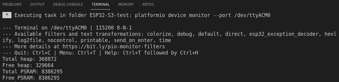
Serial.printf("Total heap: %d\n", ESP.getHeapSize());
Serial.printf("Free heap: %d\n", ESP.getFreeHeap());
Serial.printf("Total PSRAM: %d\n", ESP.getPsramSize());
Serial.printf("Free PSRAM: %d\n", ESP.getFreePsram());
delay(5000);
}And result:
Strapping Pins
| Pin | Default |
| GPIO0 | Pull-up |
| GPIO3 | |
| GPIO45 | Pull-down |
| GPio46 | Pull-down |
Care must be taken with these pins touring resetting/booting/flashing. Because ESP32 reads this these pins state. Are they High or Low and stores this info internally to configure its settings. And when they are wrong, then there can be problems.
After resetting/flashing is finished these pins work like regular GPIO pins.
PSRAM pins
OPI – Octal SPI (Serial Peripheral Interface)
PSRAM – pseudo-static random-access memory
Pins: GPIO35-37 are used by OPI PSRAM (8MB external Flash). When PSRAM is not used they can be used as normal GPIOs.
SDcard
There are two ways to use an SD card:
SPI interface – uses 4 pins
SDMMC interface has a one-bit bus mode (uses 3 pins) and a four-bit bus mode (uses 6 pins).
Four-bit mode is the fastest. One-bit mode is about 80% of the four-bit mode and SPI is about 50%.
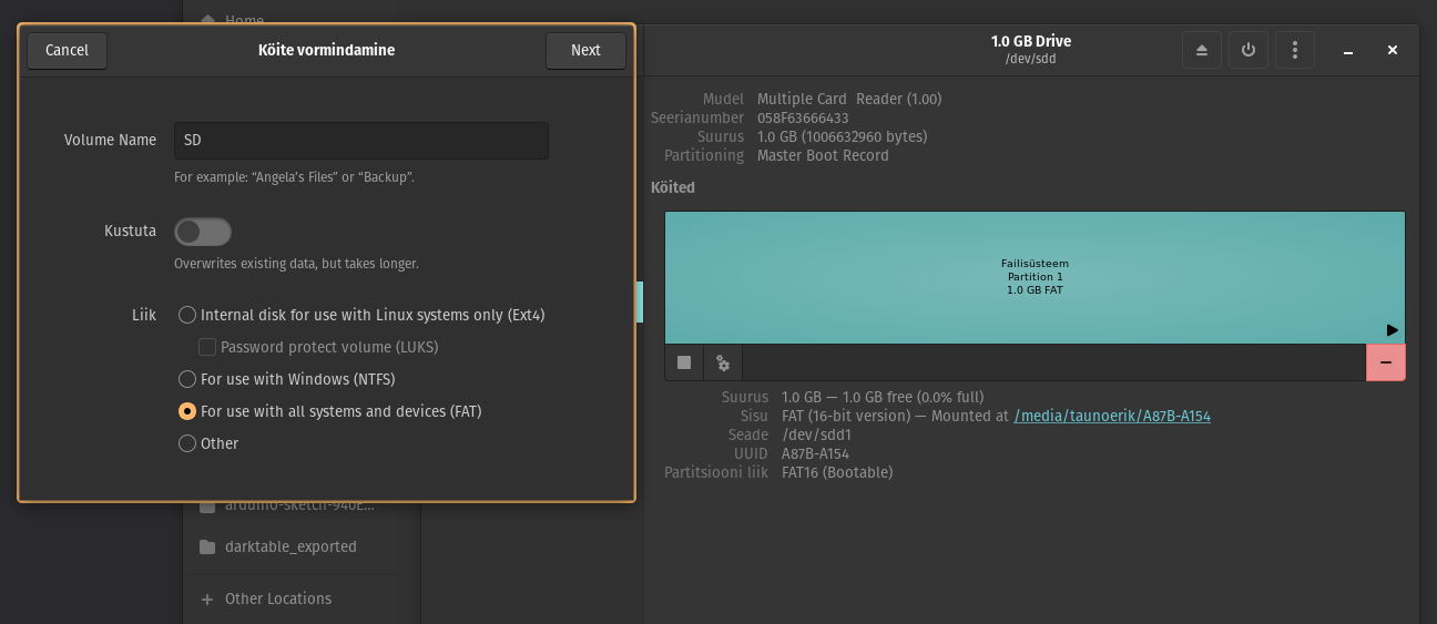
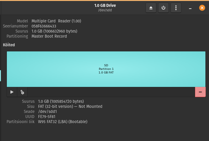
Format the 1GB micro SD card to FAT (or FAT32). Allocation unit size 16K.
SDcard uses SDMMC (Secure Digital Multi Media Card interface).
Use “SD_MMC.h” lib.
Used example code. It writes the files but does not print anything into the serial monitor.
Wifi
Modes:
- Station mode – It acts as a Wifi client.
- AP mode – it creates a hotspot network that is separate from the Internet and waits for other WiFi devices to connect.
- AP + Station mode
Wifi.begin(ssid, password,channel, bssid, connect)
ssid: WiFi hotspot name
password: WiFi hotspot password
channel: WiFi hotspot channel number; communicating through the specified channel; optional parameter
bssid: mac address of WiFi hotspot, optional parameter
connect: optional boolean parameter, defaulting to true. If set as false, then ESP32-S3 won’t connect to WiFi.
Wifi.config(local_ip, gateway, subnet, dns1, dns2): set static local IP address.
local_ip: station fixed IP address.
subnet:subnet mask
dns1,dns2: optional parameter. define IP address of domain name server
Arduino settings
Borad manager URL:
https://raw.githubusercontent.com/espressif/arduino-esp32/gh-pages/package_esp32_index.jsonBoard: ESP32S3 Dev Module
