Project started November 13, 2025.
I gradually added material as the project progressed.
Goal
I need a sensor that can detect whether an object is in the desired location or not. Must use 24V input voltage, common in industry. Pass the signal on to either another microcontroller or a robot. The user must be able to easily adjust the sensitivity or distance of the sensor.
Plan
The plan is to make a custom printed circuit board (PCB) that will hold:
- Power module – To convert 24V to a low voltage suitable for the microcontroller. OKY3504-1 Mini-360 DC-DC buck converter 4.75V-23V to 1V-17V step down power module.
- Development board – Raspberry Pi Pico 2 RP2350. The board brain.
- Sensor – ToF VL53L0X Time Of Flight distance sensor.
- Display – To display current sensor readings and user-set parameters. 0.96″, 128×64 px, I2C, OLED Display Module. Driver IC: SSD1306.
- Rotary encoders – User input. 360-degree rotation. With a push button.
- Indicator LEDs (Red and green) – To quickly interpret sensor readings.
- Optocouplers – PC817. Galvanically isolated signal output.
- Screw terminals – To connect the sensor, power input, sensor output and other possible connections.
Since this project is still in its early stages, I reserve the right to make changes at a later stage. Therefore, I will add most MCU pins to the PCB.
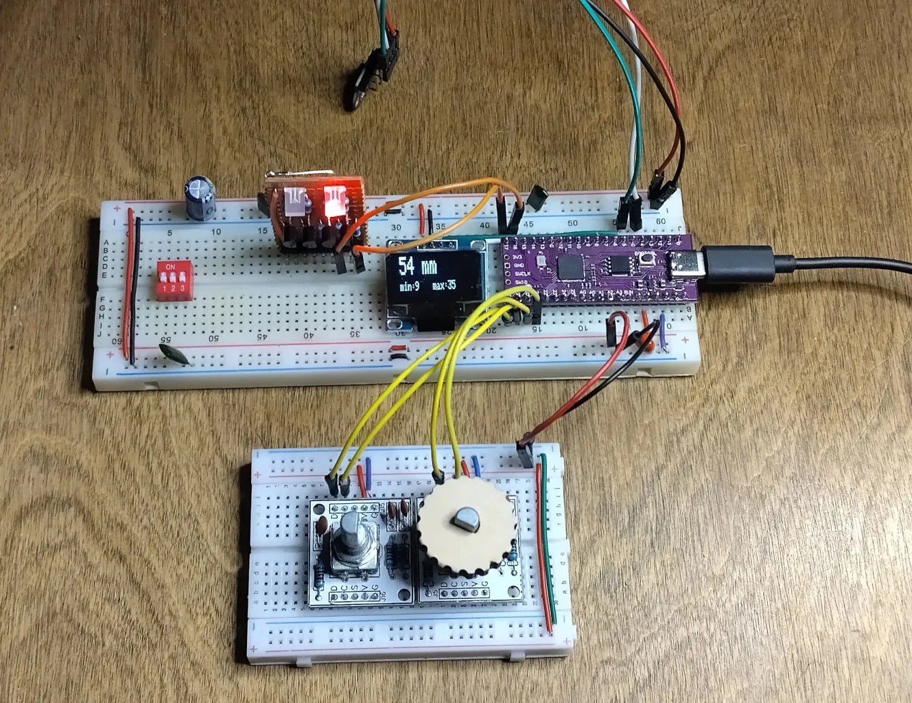
The first prototype on the breadboard
It uses a Pico 1 (RP2040) clone.
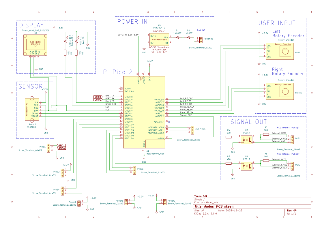
Prototype schematics
I designed the schematics and a 2-layer PCB in KiCAD. Added new symbols and footprints to modules that I needed, but didn’t exist in the library. I left the same pin order to symbols as on a real modules. To avoid pin order mistakes. Like on the OLED module, the VCC and GND pins can be in reverse order.
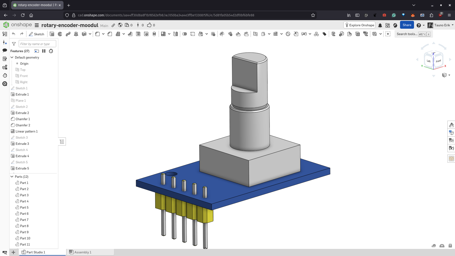
In OnShape, I designed simple 3D models that I exported as STEP files.
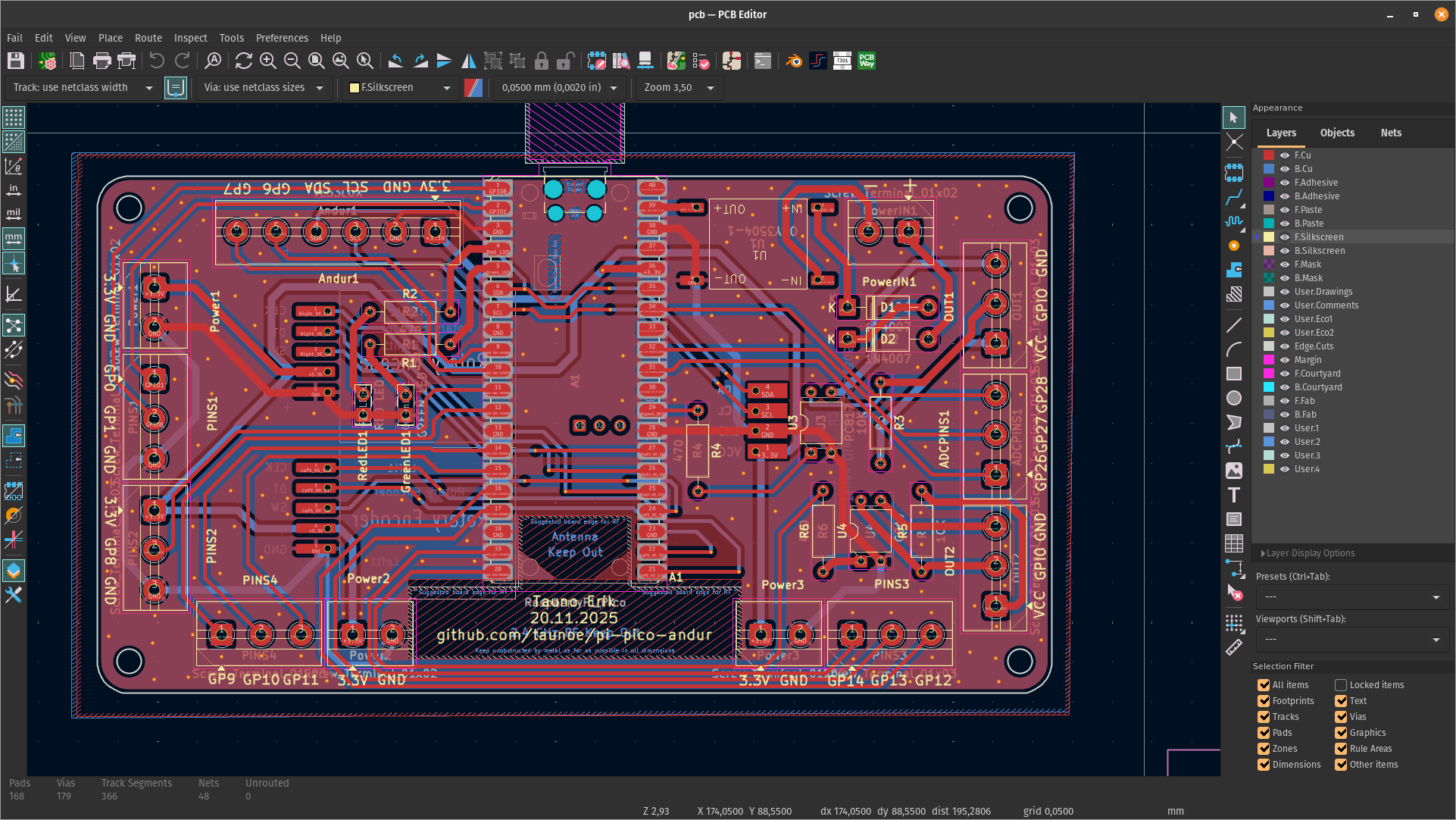
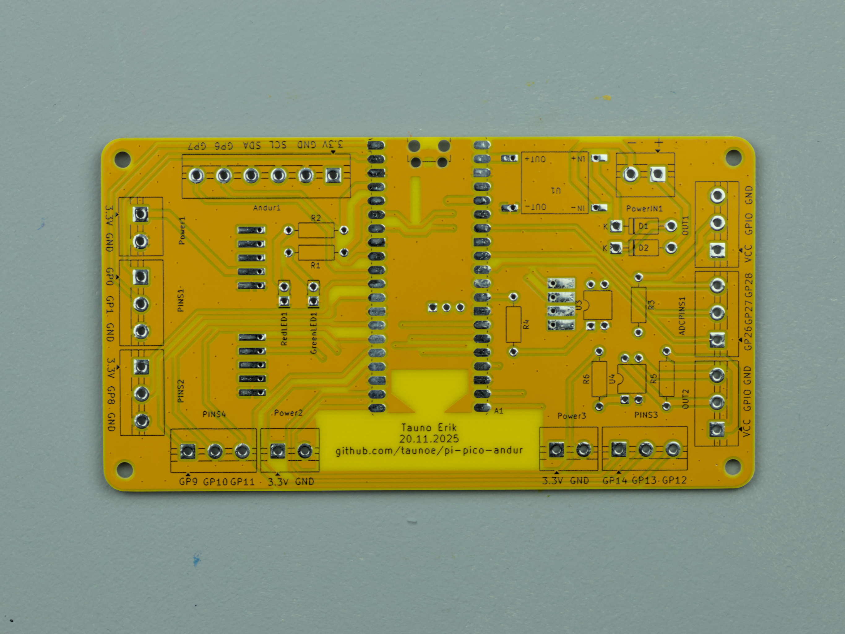
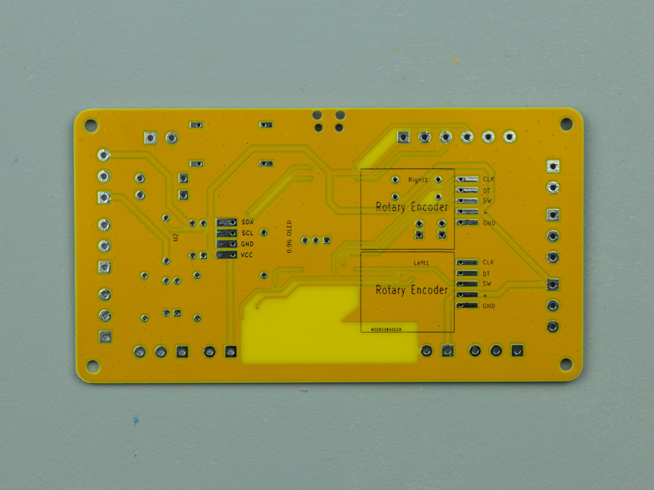
PCBs
Fortunately, when I designed the prototype, PCBWay contacted me to support PCB fabrication. I have ordered a lot of printed circuit boards from them. And they will always be produced quickly, and the quality is good. I have never had any problems.
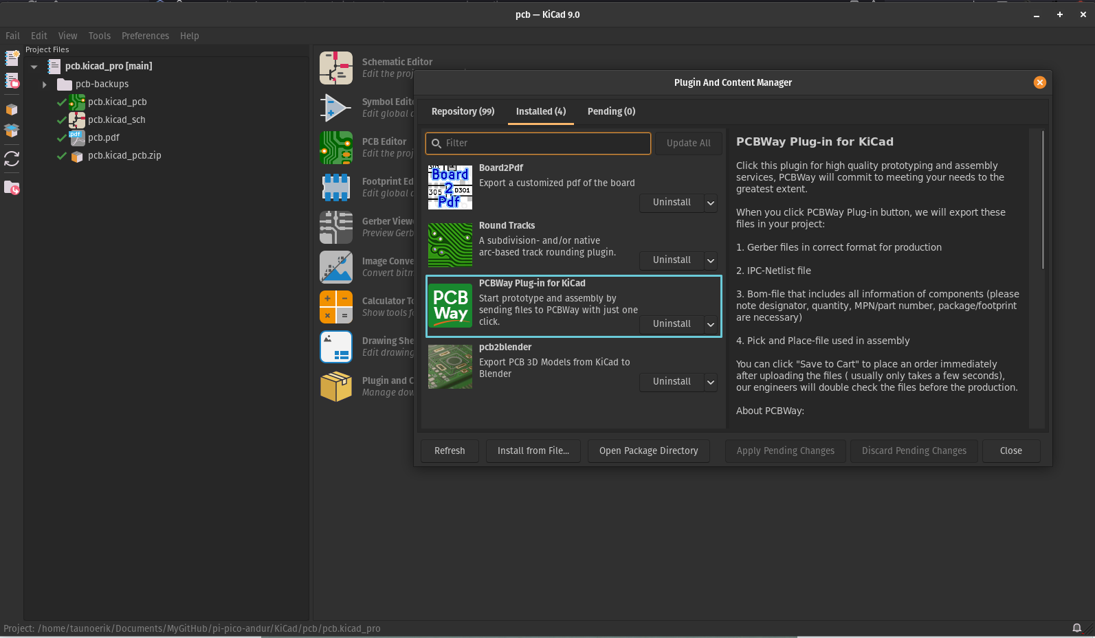
KiCAD has a plugin that allows you to quickly upload files to PCBway and place an order. You can directly install it from the KiCad Plugins window. Search “PCBWay”. It makes the ordering process simple. You don’t have to worry about whether you added all the layers and files. I ordered 10 yellow PCBs with a black silk screen. The yellow silk screen is not as bright as I like. But not bad. I like the board colour where there is no copper layer. Maybe next time I order one without copperfill.
My design is now more like a Raspberry Pi Pico expansion board. And maybe next time I will make it smaller and with fewer pins. But now I added them all so I can use it more than one purpose.
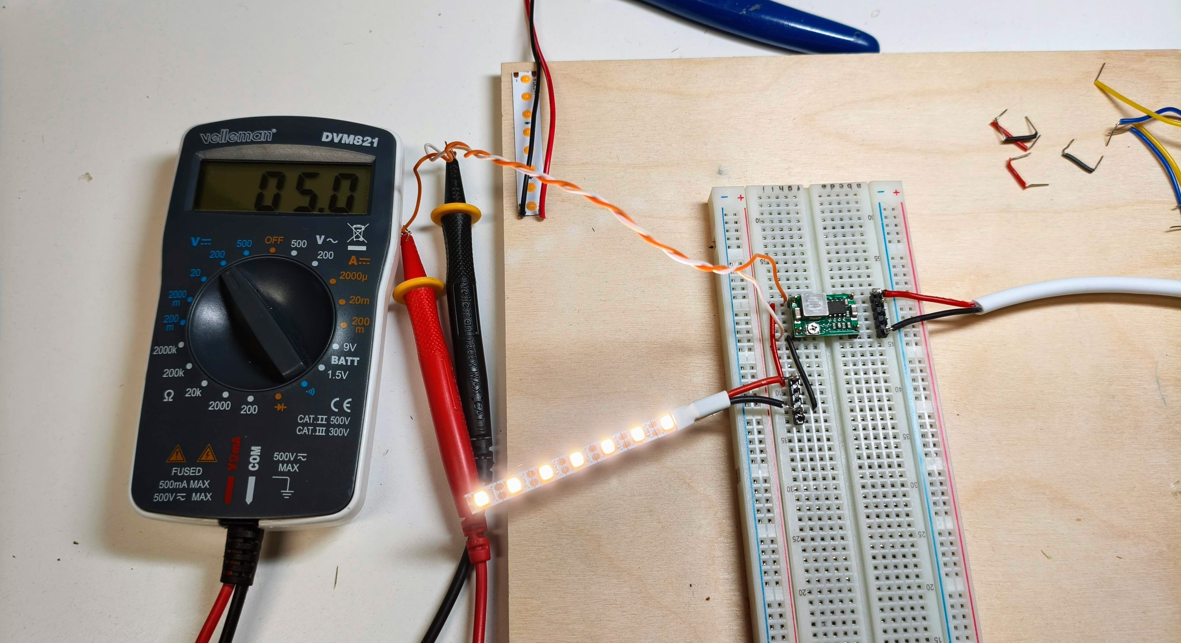
Power module
Because the Raspberry Pi Pico input voltage is 1.8V to 5.5V, I needed to configure the power module to the right output voltage. I use the OKY3504-1 DC-to-DC step-down converter. The input voltage is 24V, and the output is 5V.
I set up a breadboard to configure it. There is a little screw on the board for that.
Sensor module
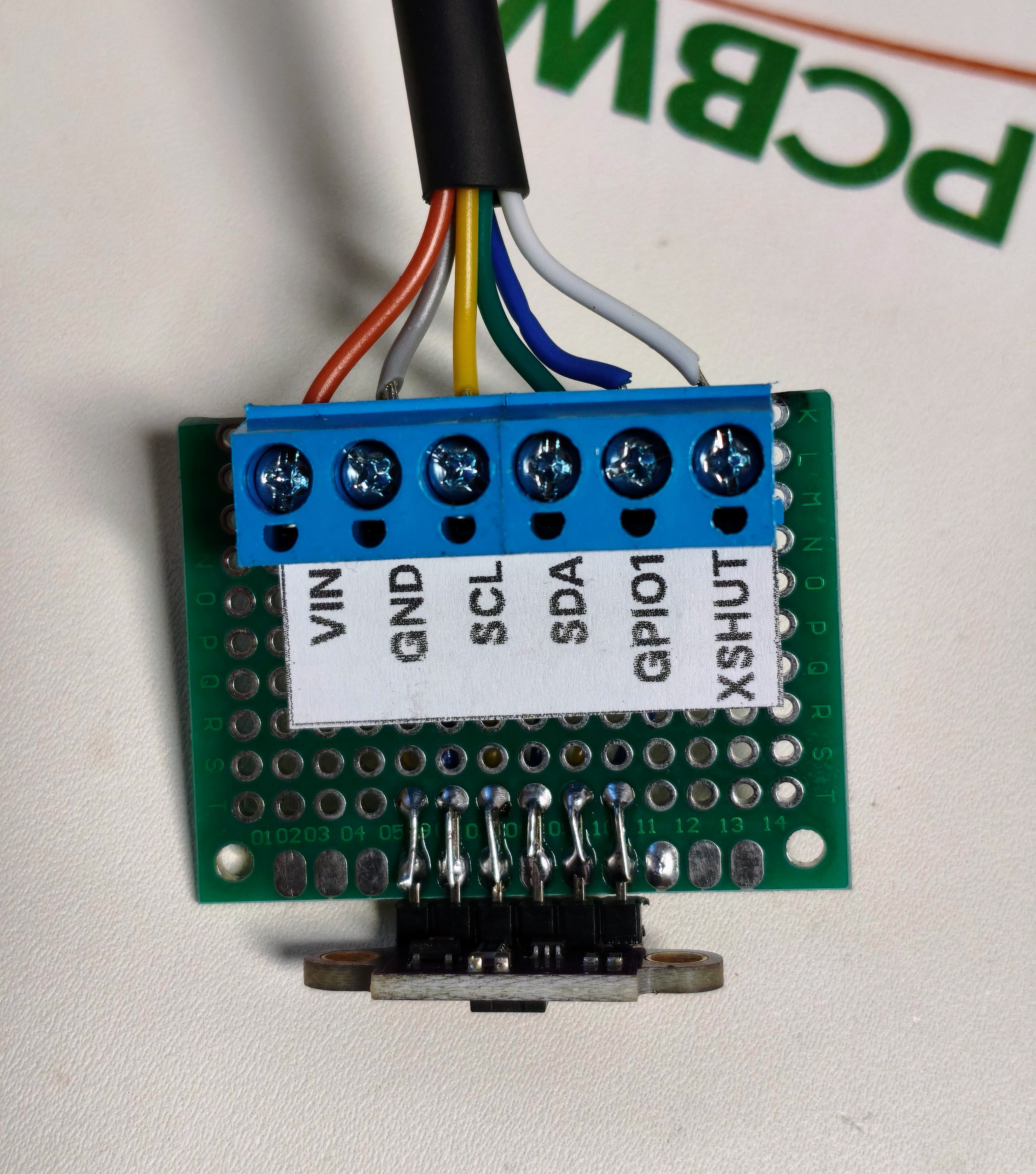
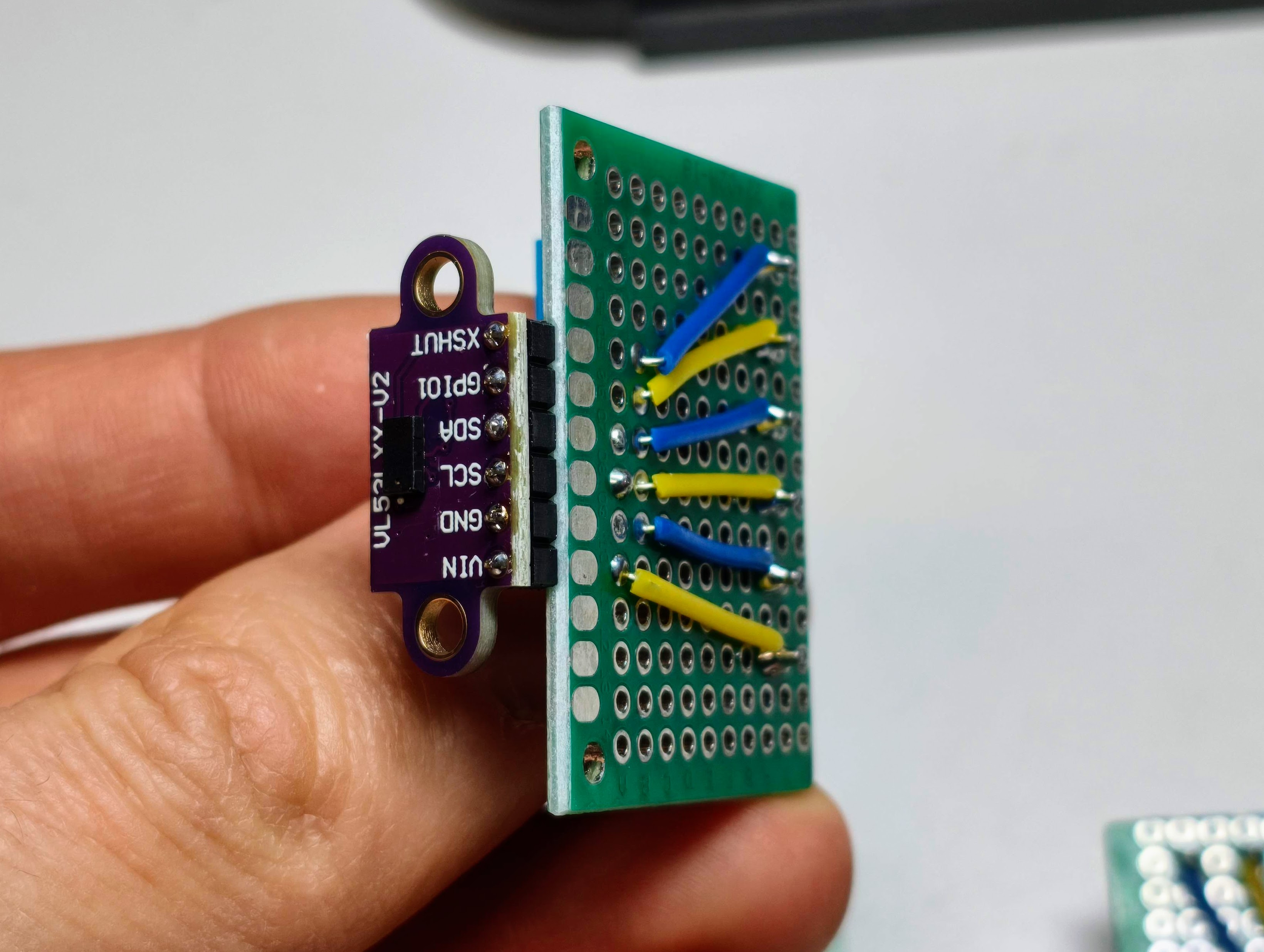
Case for Sensor v1
I made a simple case for the sensor from plywood. It is made of 4 mm plywood and laser cut.
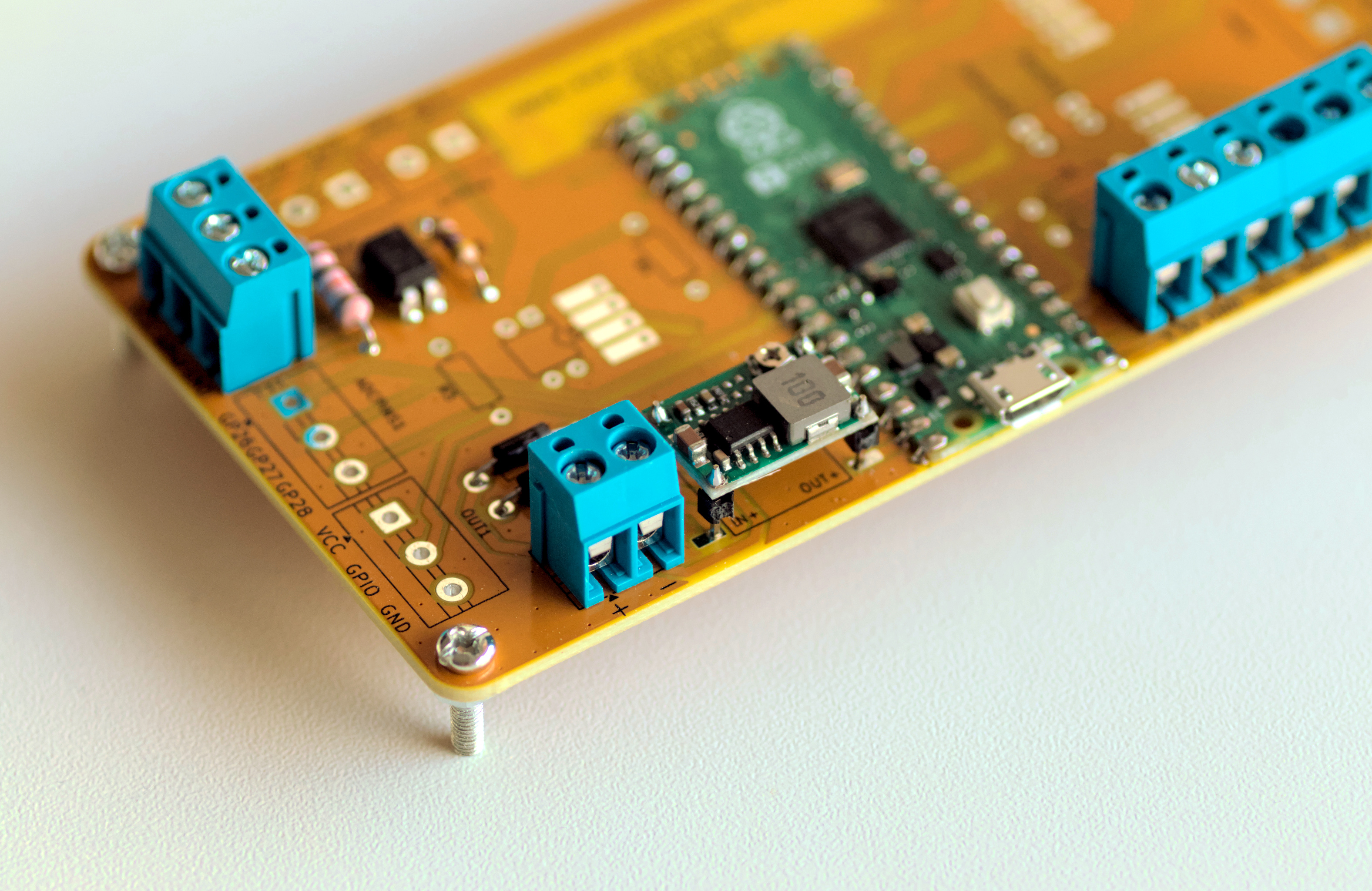
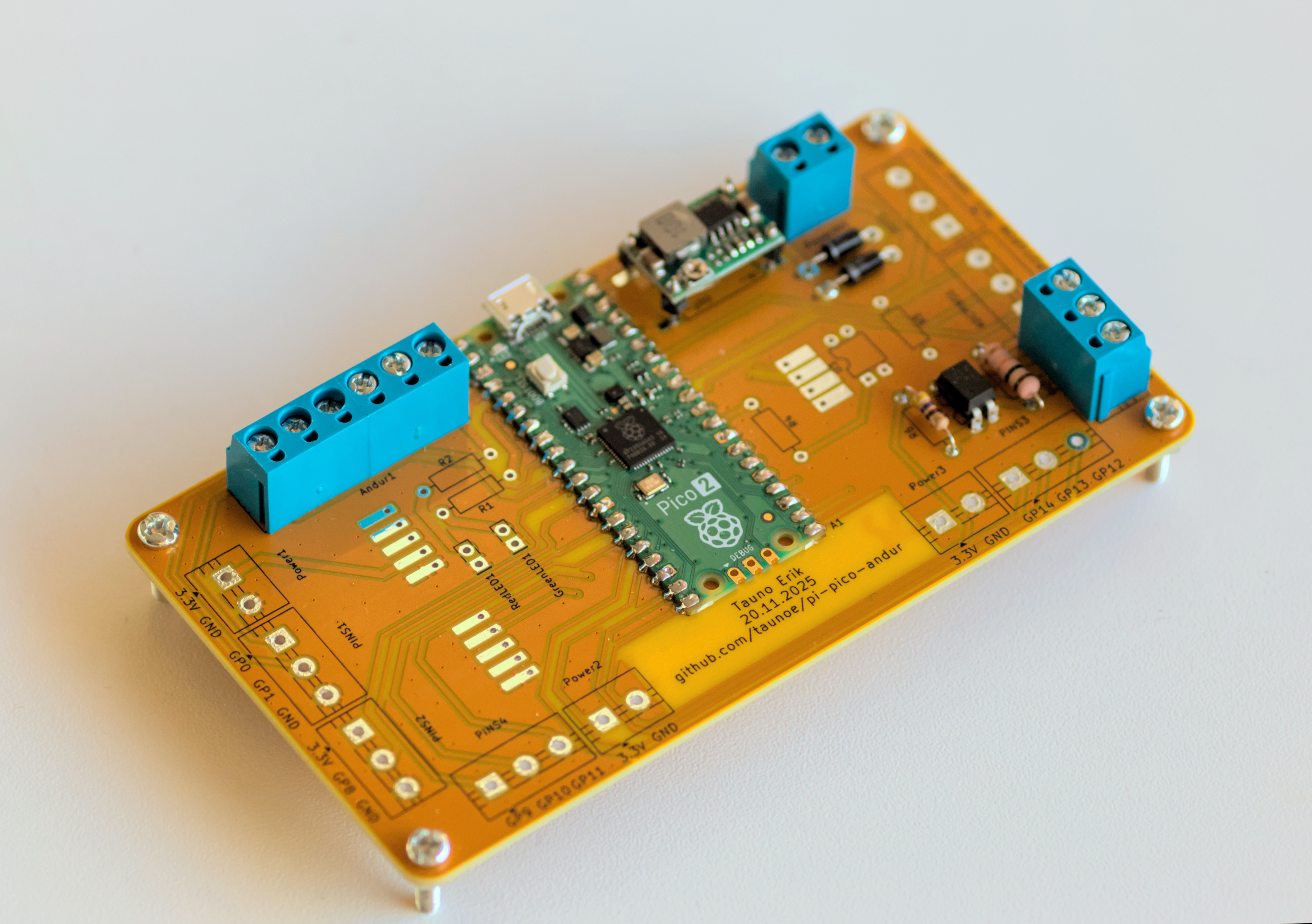
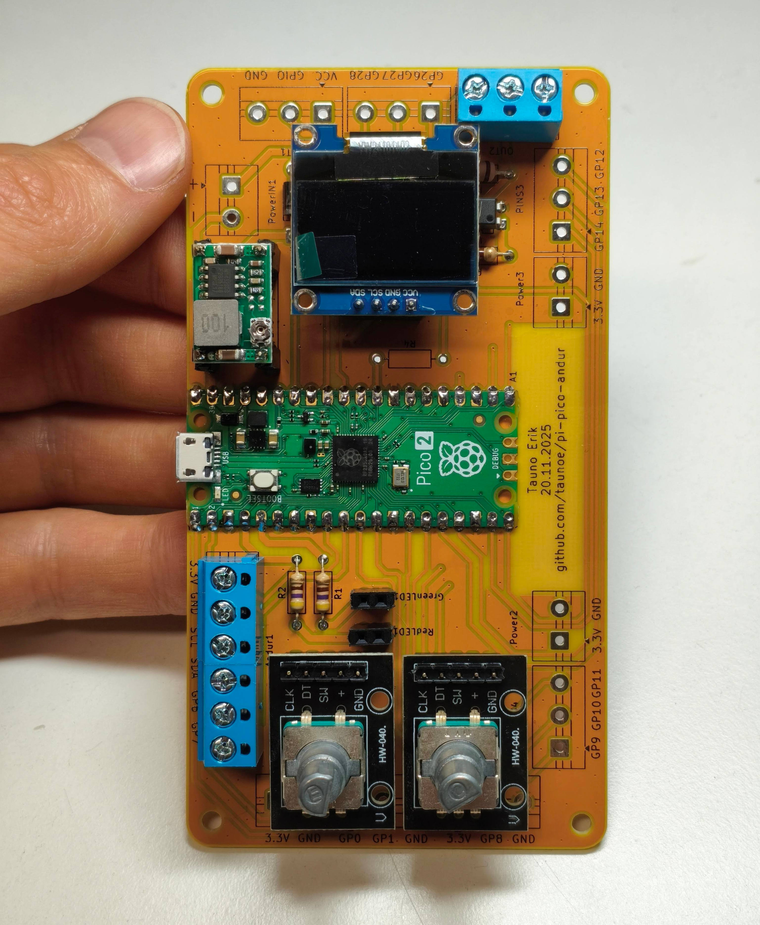
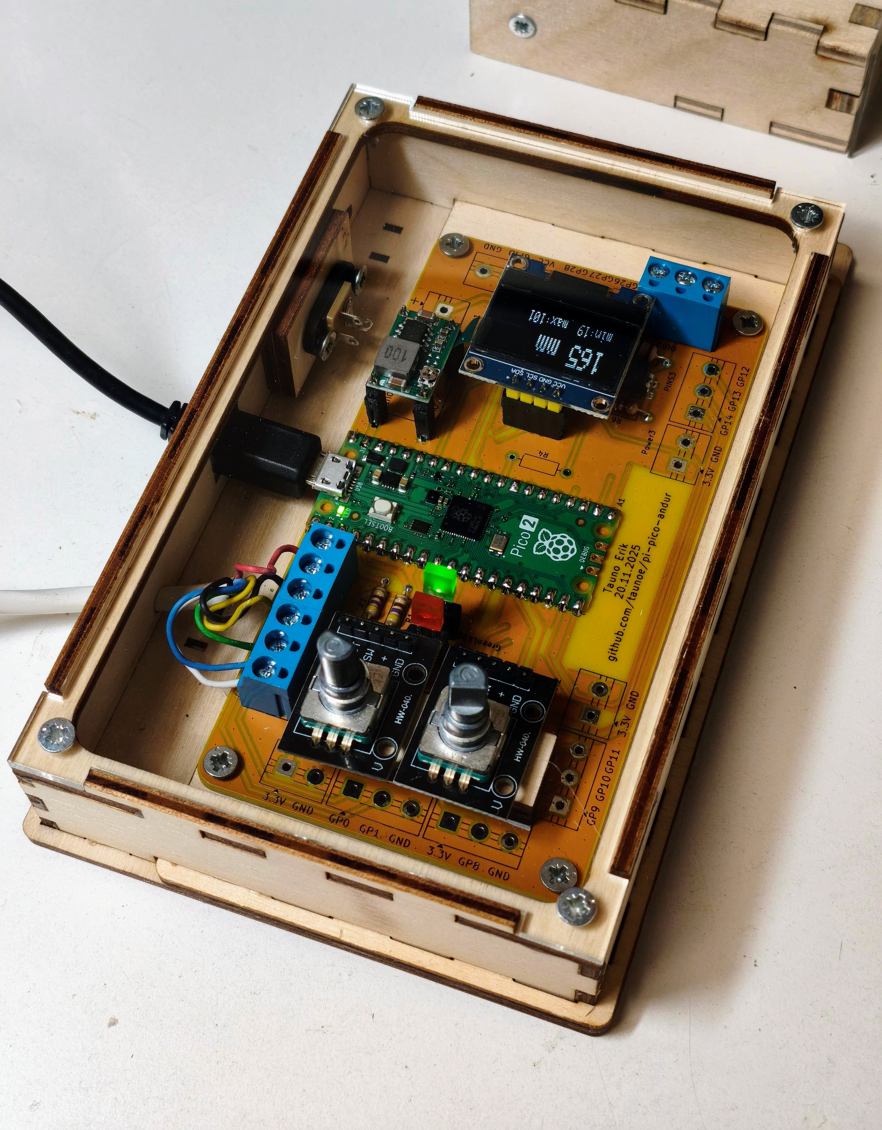
Assembled PCB
Project box v1
The first project box consisted of two parts. Connected with the hinge. It was a complicated design and assembly.
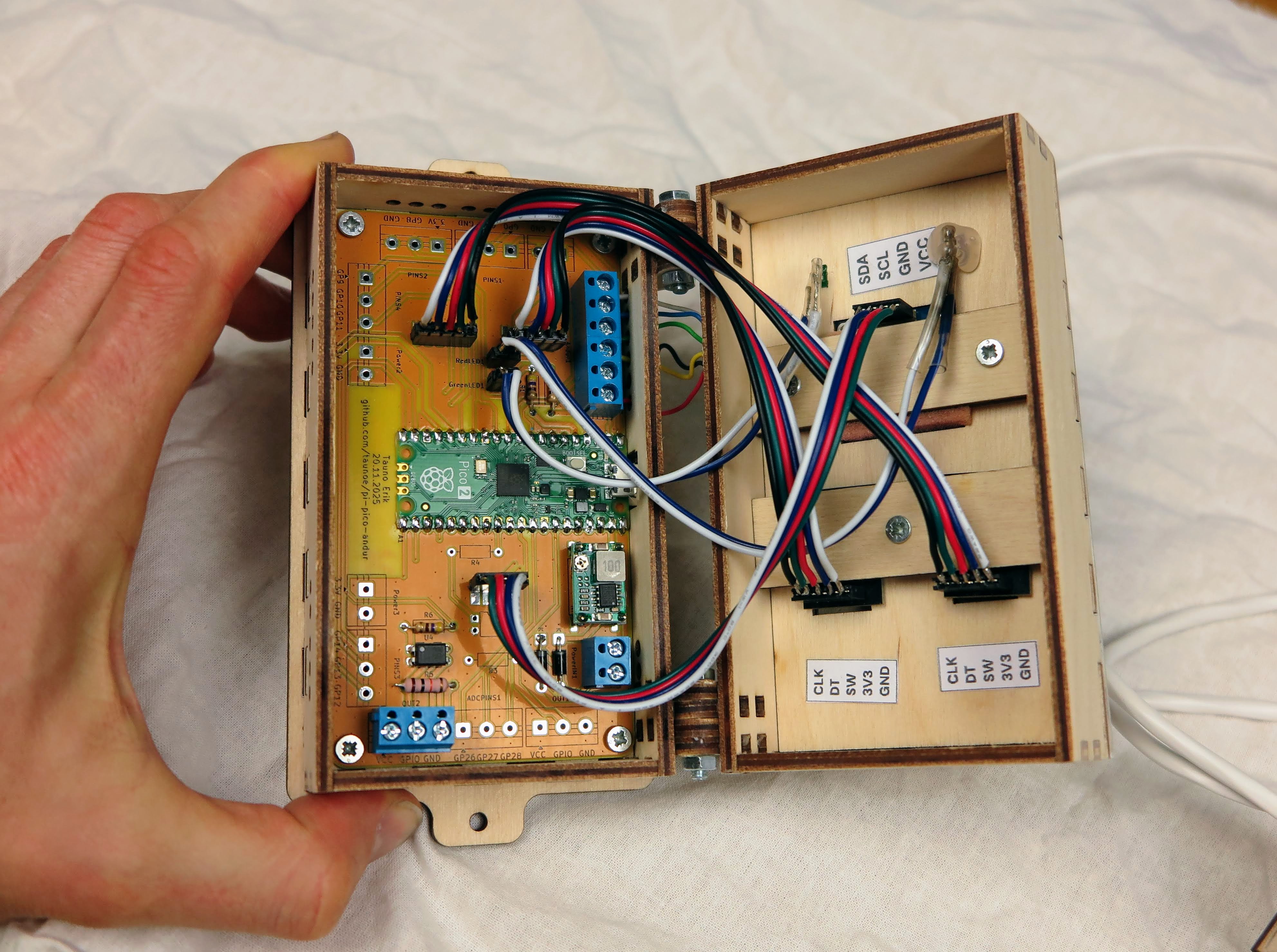
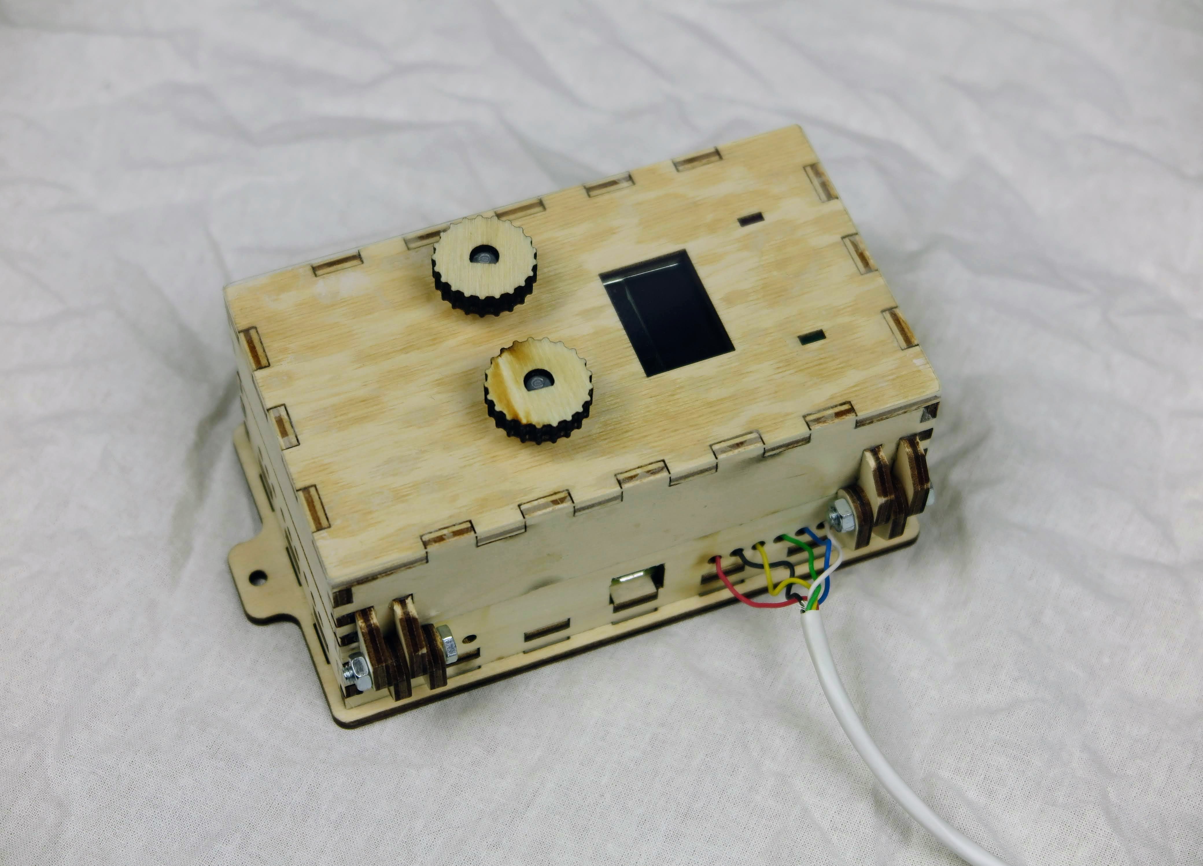
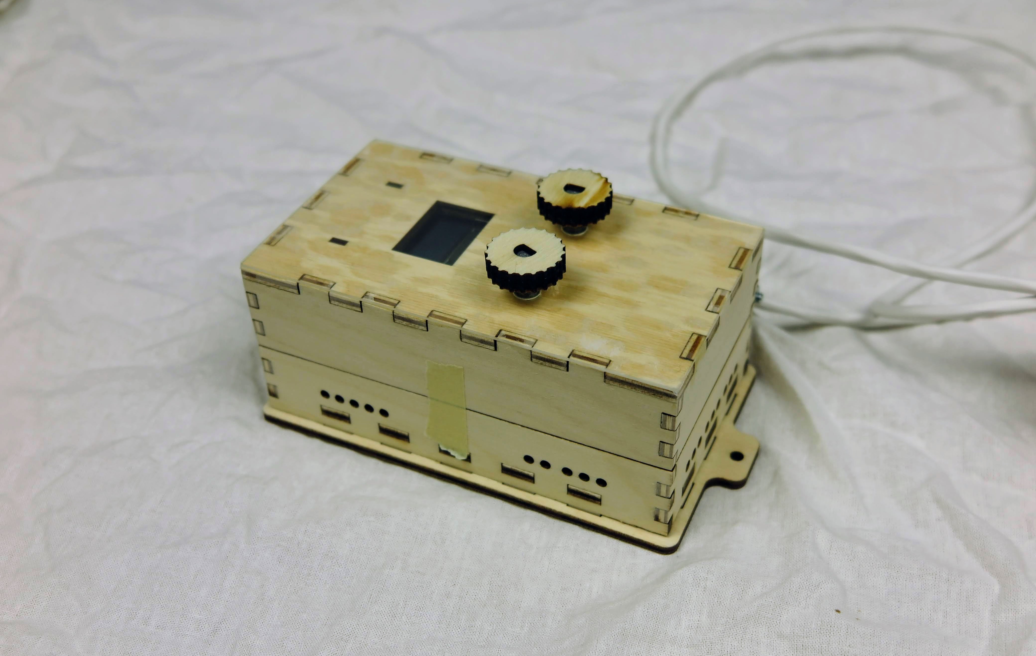
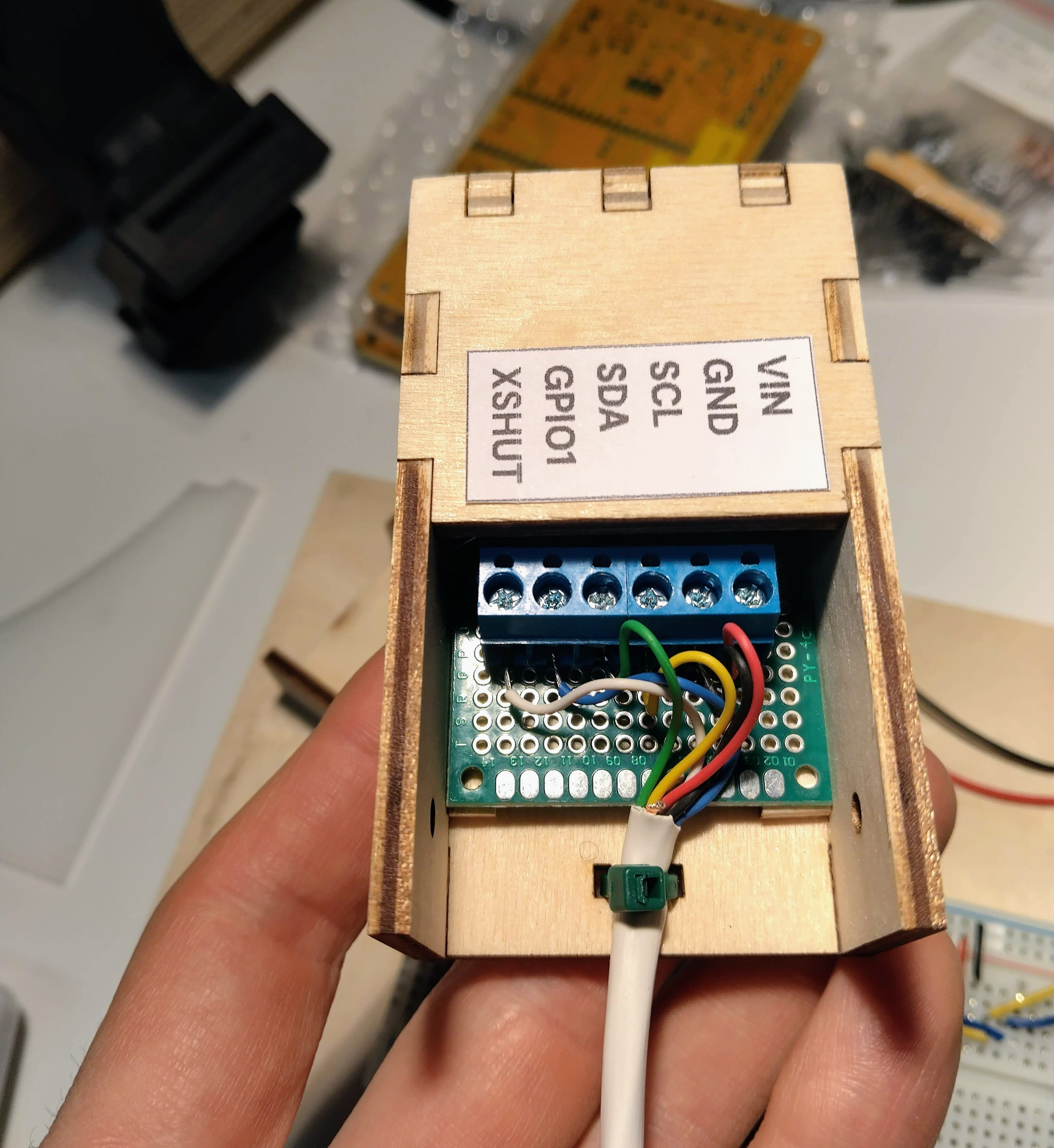
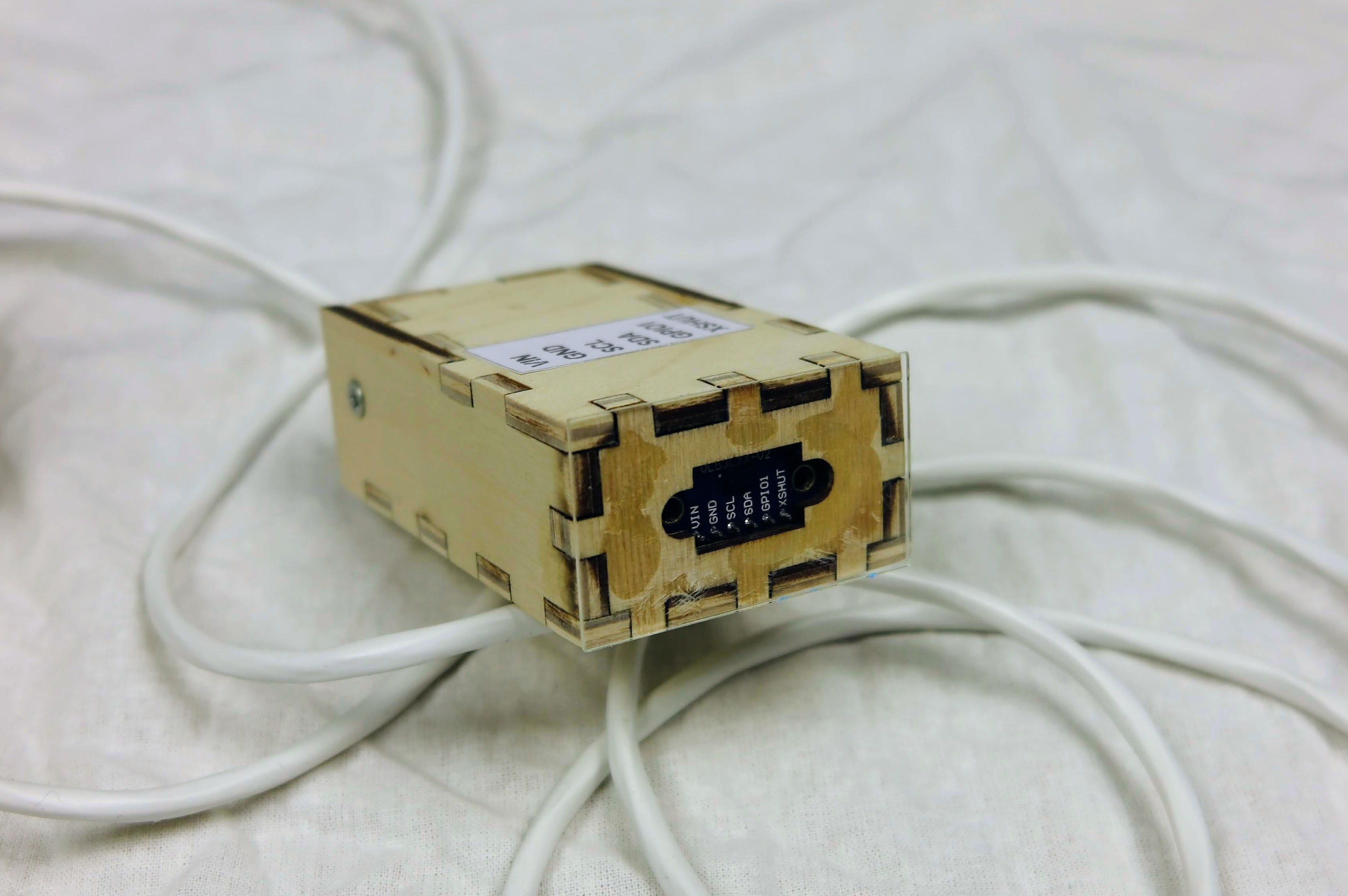
Project box v2
In the second version, I simplified the box design. There is now only one box with an acrylic cover.
First demo with a new project box:
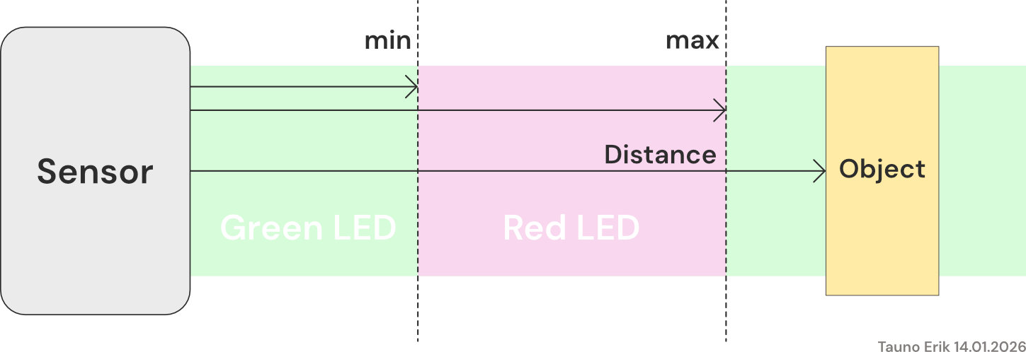
The working principle of the sensor. The left cnob is to set the min. distance and right one set the max. distance. When the object is between min and max, then the output signal is in the ON state, and the red LED is on.
Code
The project code can be found on GitHub: https://github.com/taunoe/pi-pico-andur/tree/main/firmware/PlatfoemIO-Pico-2/Andur
I use PlatformIO and maxgerhardt core. It’s a work in progress now.
Future improvements
- Add isolated input from the robot or other device.
