
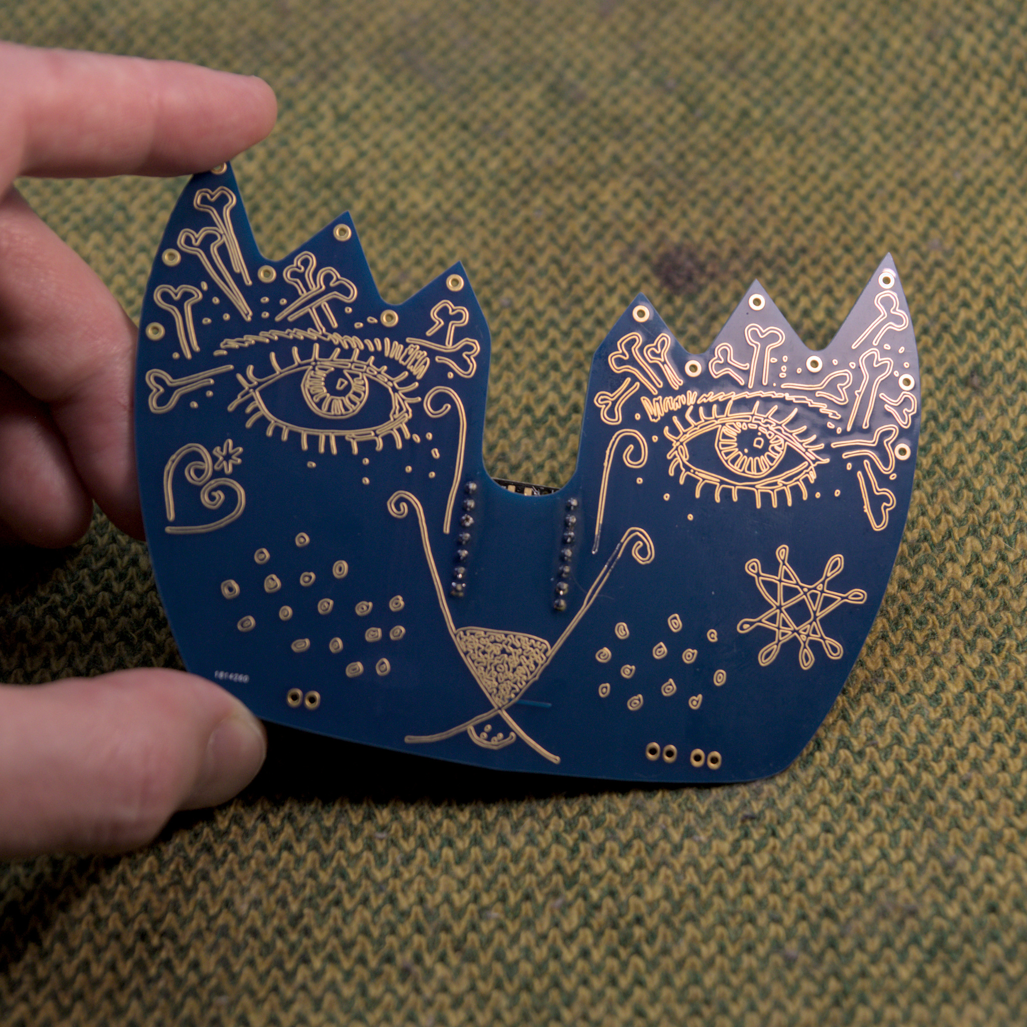
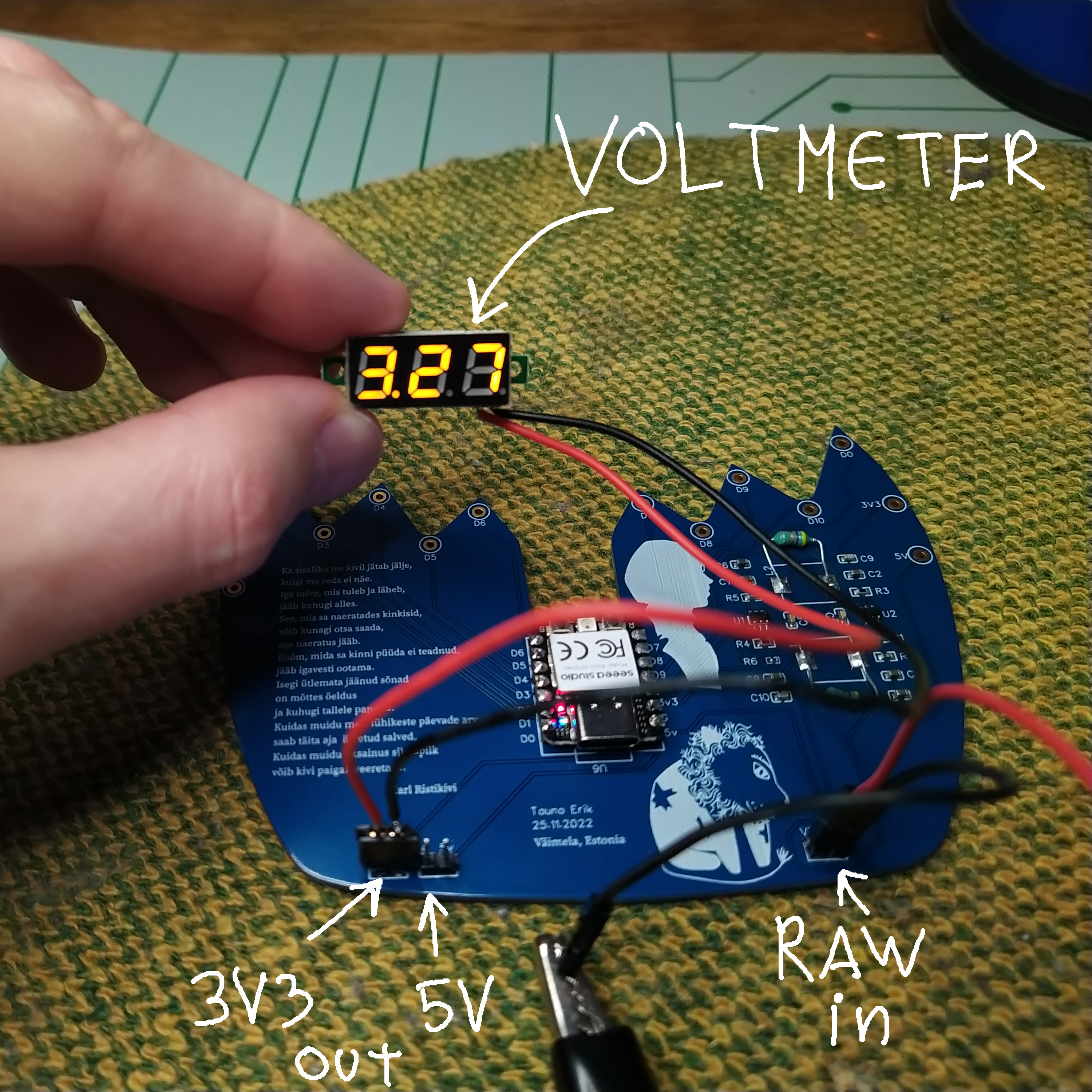
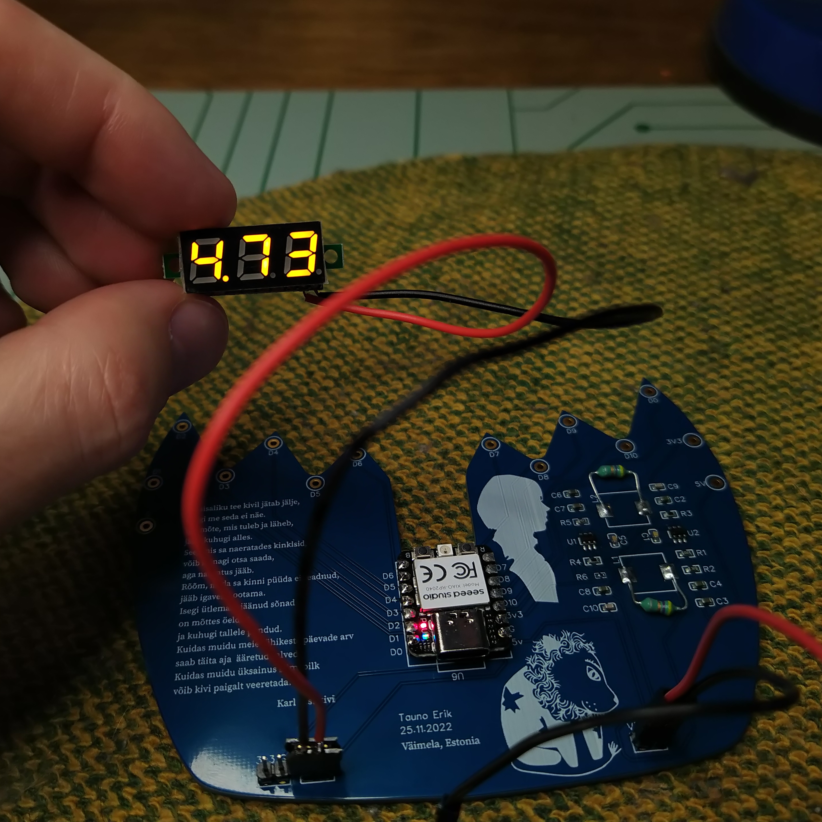
My face-shape PCBs have arrived – kindly made by Seeed Studio Fusion service. On the backside, there are one XIAO RP2040 microcontroller and two synchronous buck converters to make 5 and 3.3 voltages.
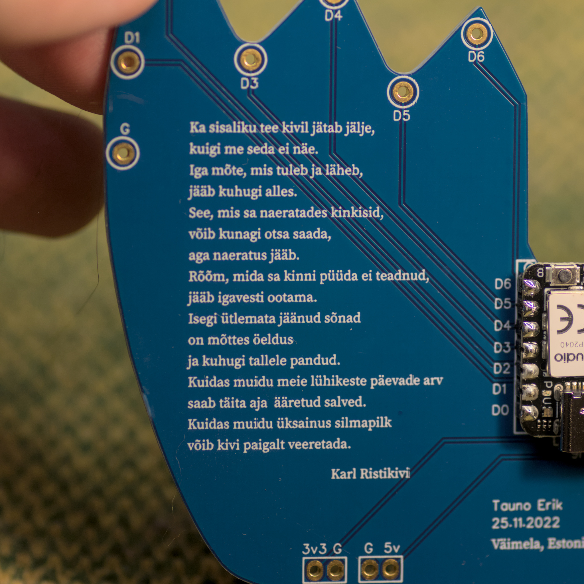
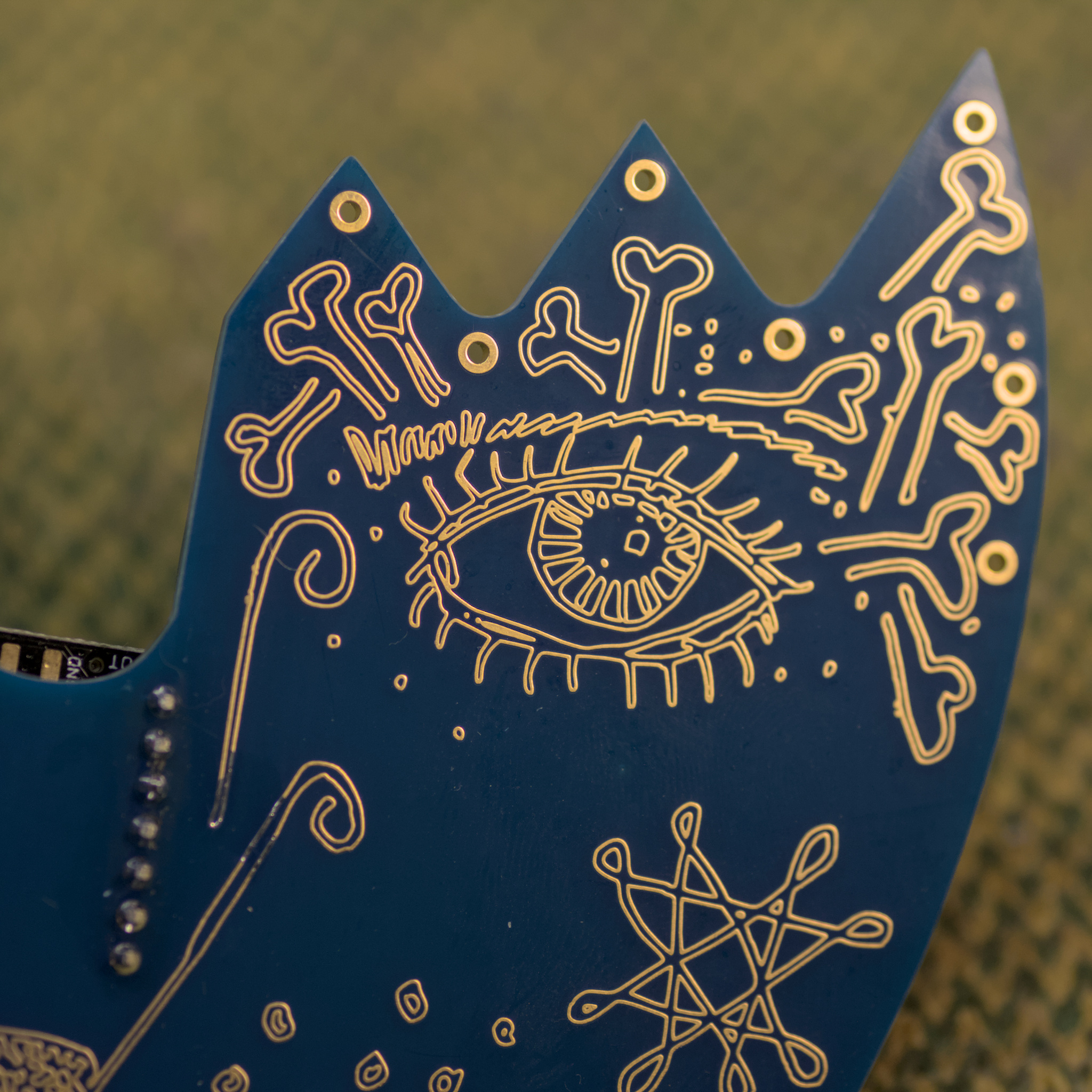
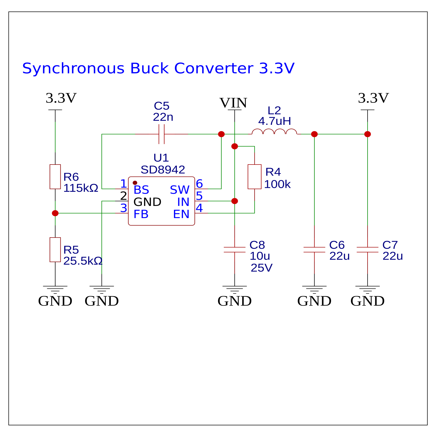
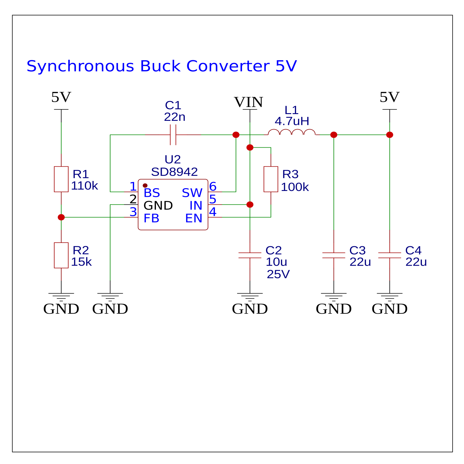
I found these Synchronous Buck Converter schematics, made by @wagiminator I incorporated them into my board design and it works pretty well. Input voltage 4.5V – 16V. The output voltage depends on resistors. And I didn’t have the right size SMD inductors so I used through-hole ones.
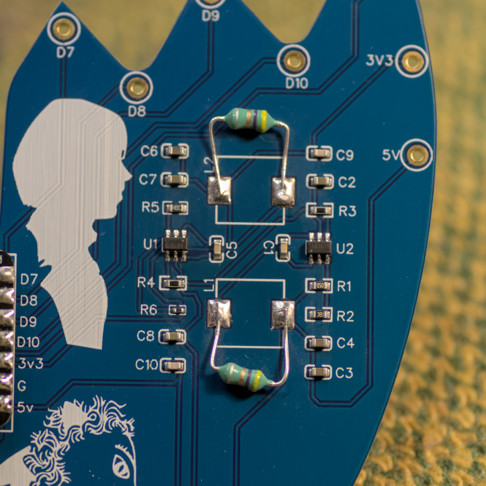
Unfortunately my design contained two mistakes:
- Wrong footprint size for inductors (L1, L2). That was easy fix as you can see from images.
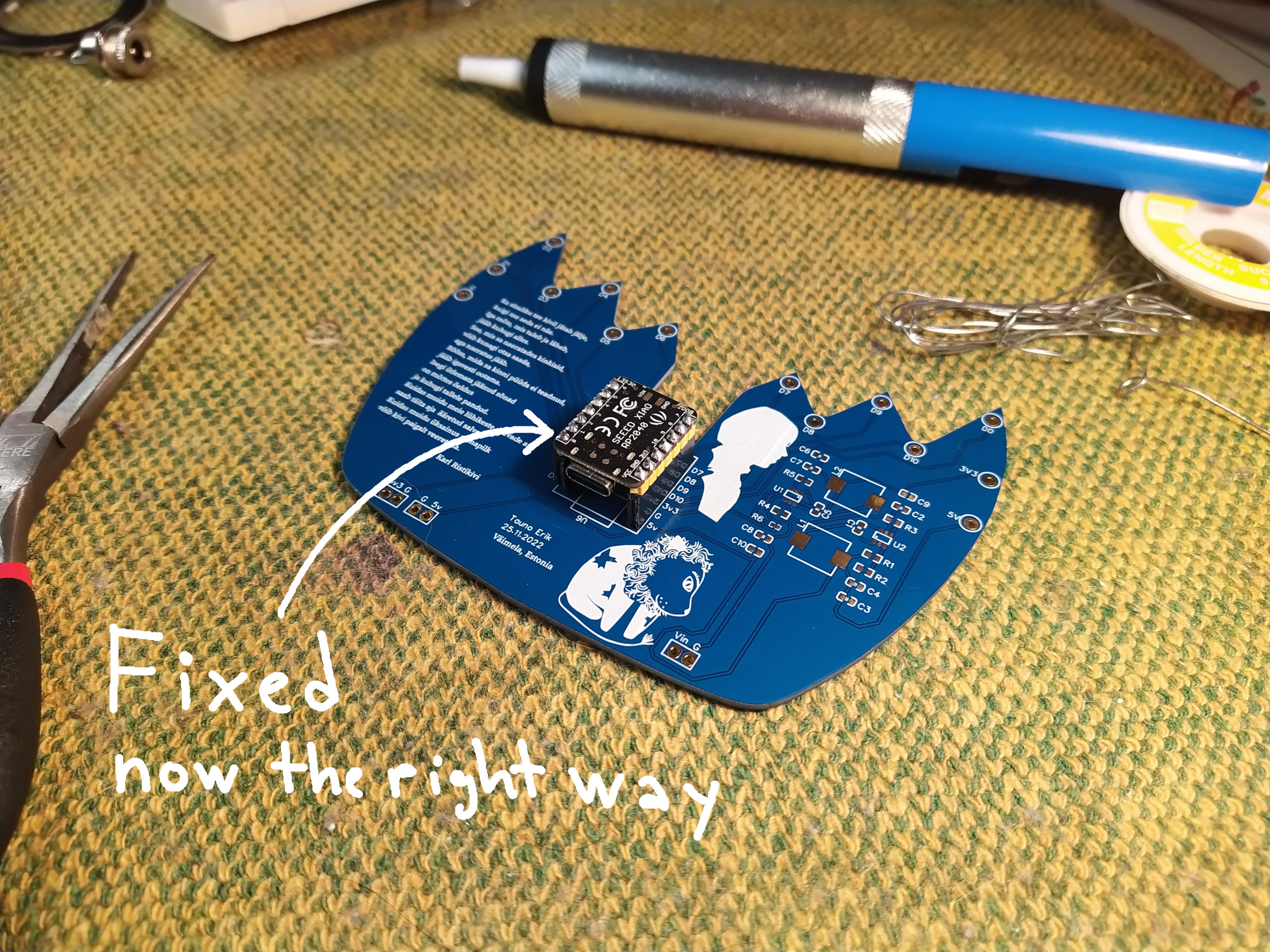
- MCU board pins are flipped. Those on the left are on the right and vice versa. So I have to desolder it and turn around.
My previous post about this project.
