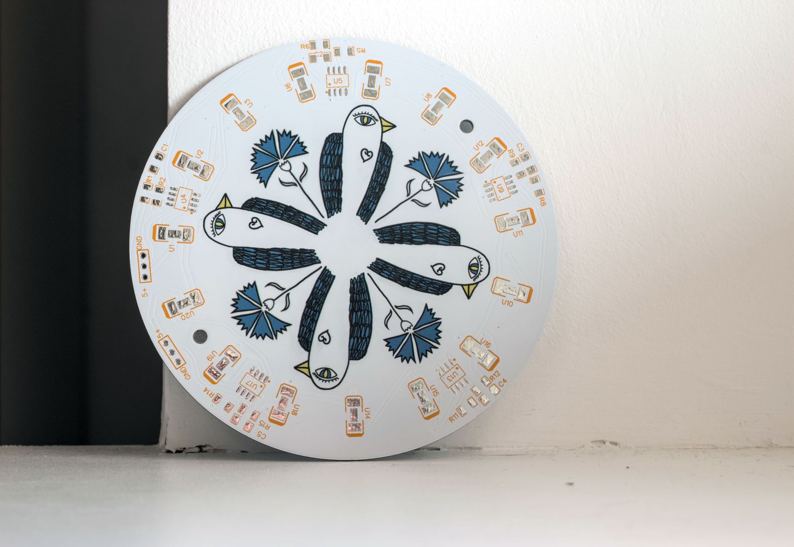
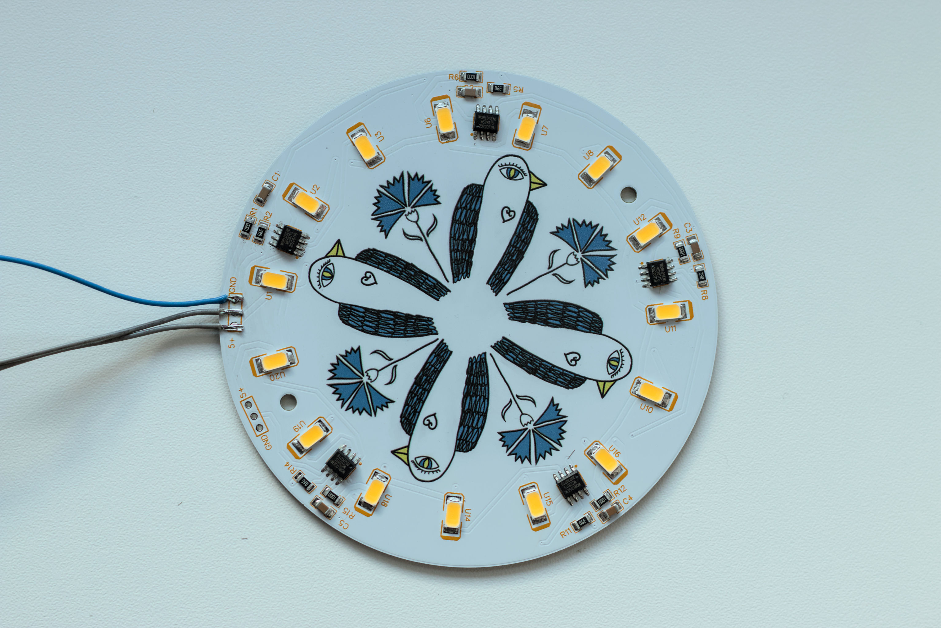
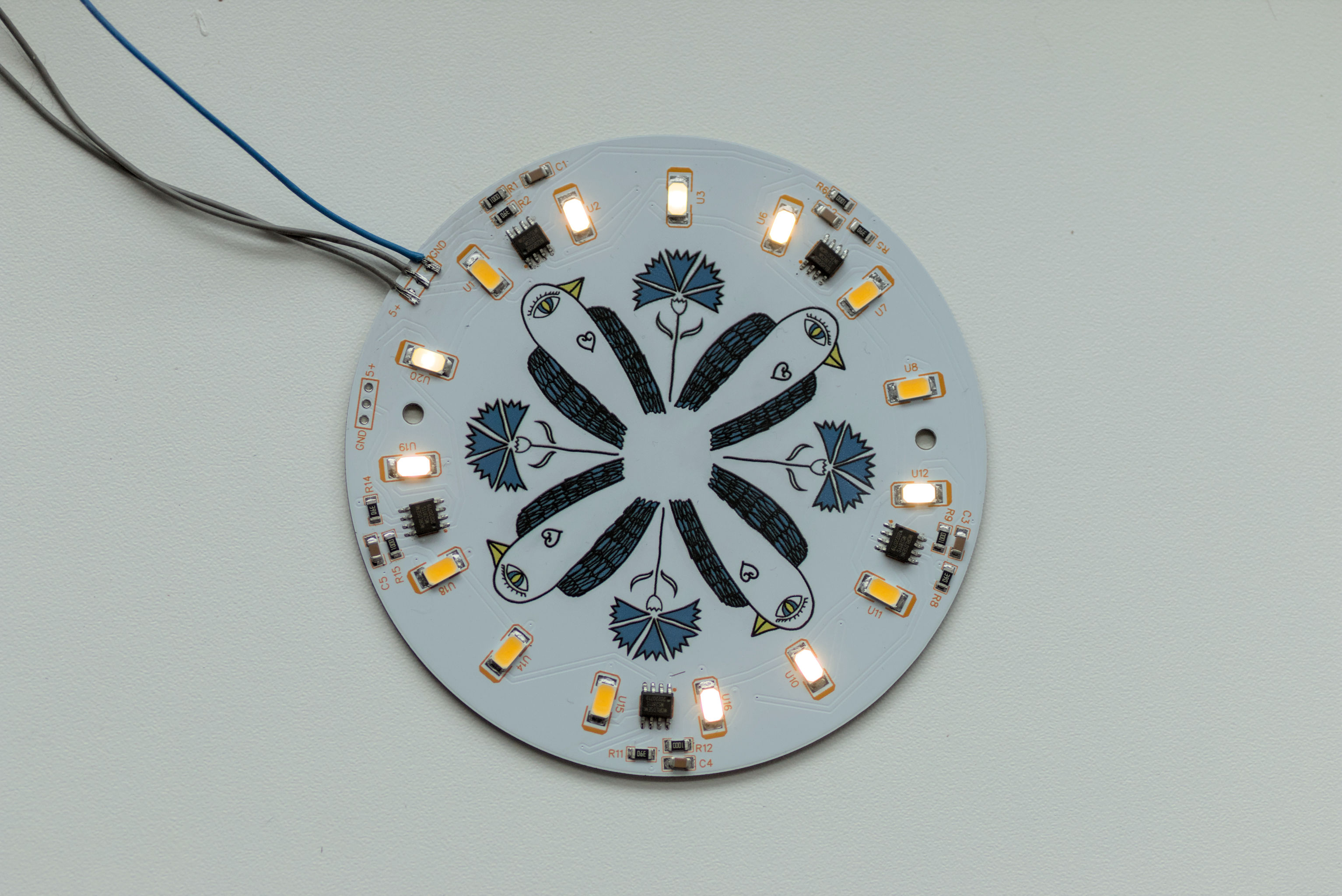
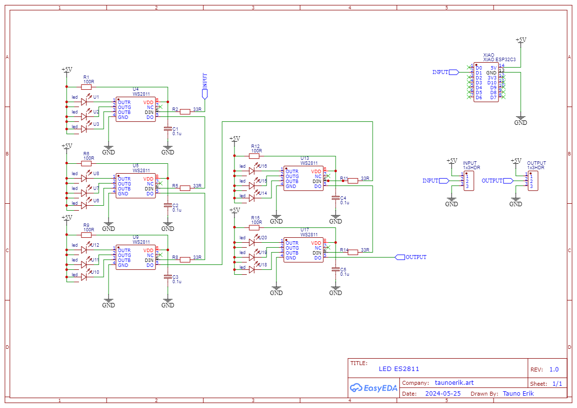
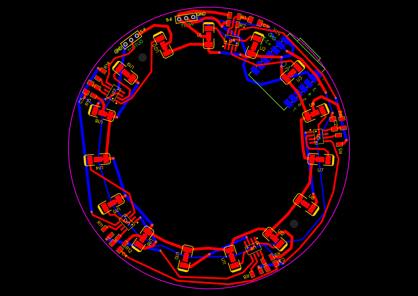
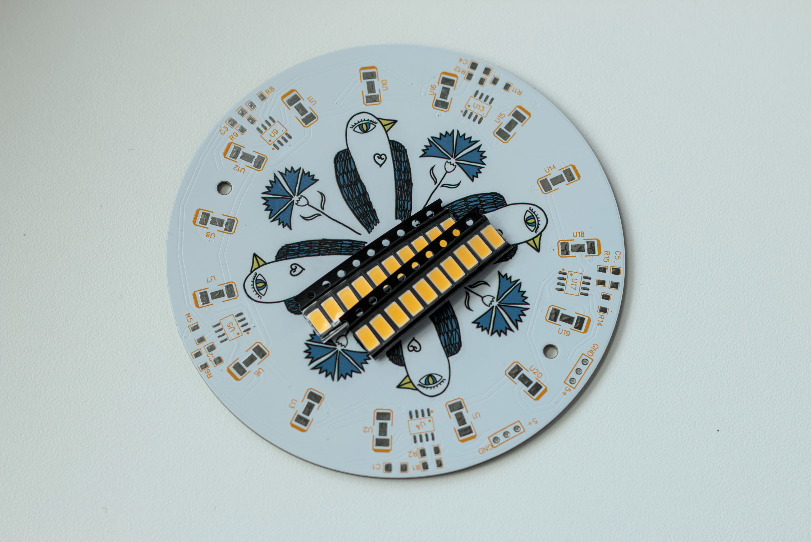
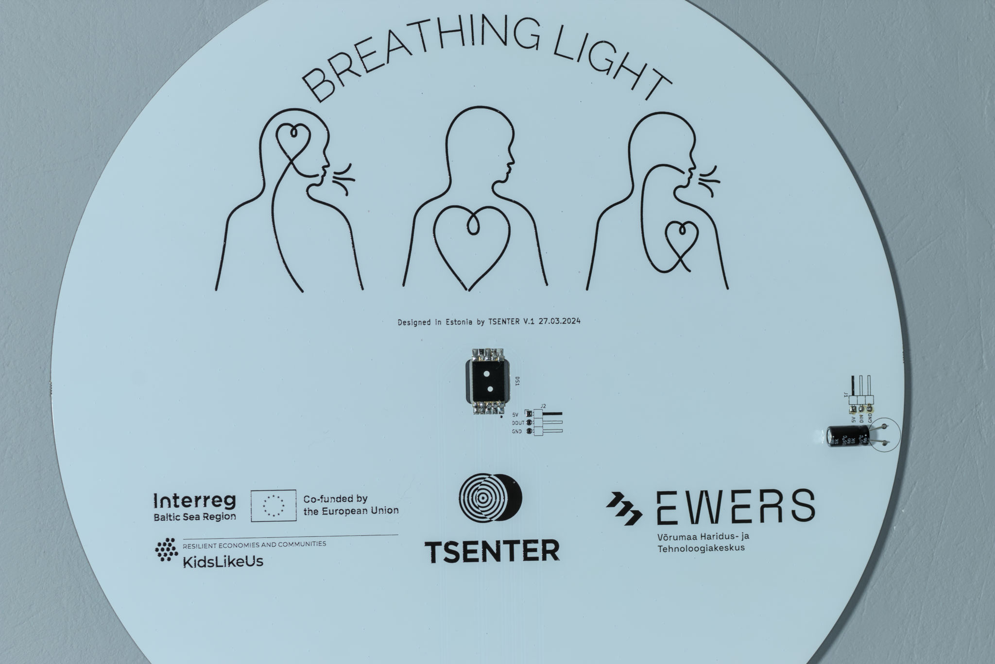
Üks LED valgusti 15 LEDiga. LEDe juhitakse läbi WS2811 kiipide, mis lubab kõikide LEDide heledust kontrollida individuaalselt. Tahaküljele saab kinnitada ka Seeedstudi XIAO arendusplaadi. Või siis kontrollida eraldi oleva mikrokontrolleriga. Mina kasutan siin ESP32te. Neid valgusteid saab ka järjestiku mitu tükki üksteise järgi. PCBd valmistas ja printis PCBWay. Komponendid jootsin ise. PCB läbimõõt 10cm.
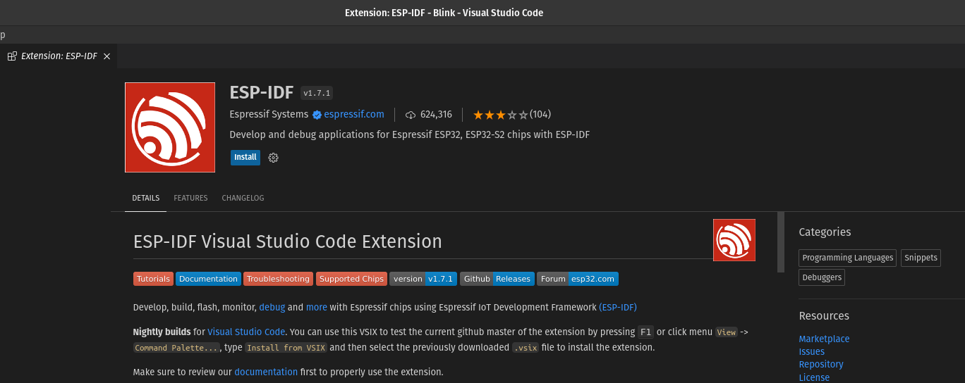
ESP-IDF is Espressif’s official IoT Development Framework for the ESP32, ESP32-S, ESP32-C and ESP32-H series. It provides a self-sufficient SDK for any generic application development on these platforms, using programming languages such as C and C++.
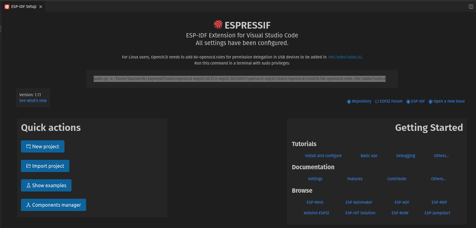
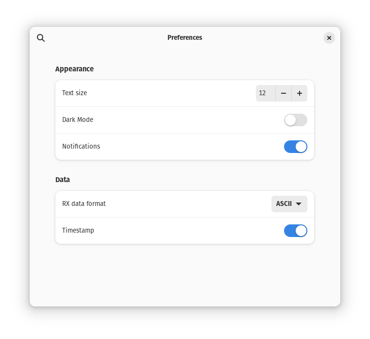
Select an Espressif target (esp32, esp32s2, etc.) with the ESP-IDF: Set Espressif Device Target command. Default is esp32.
Configure your project using menuconfig. Use the ESP-IDF: SDK Configuration Editor command (CTRLEG keyboard shortcut ) where the user can modify the ESP-IDF project settings.
Open the project configuration menu (idf.py menuconfig).
Build the project, use the ESP-IDF: Build your Project command (CTRLEB keyboard shortcut).
Blink example code
#include <stdio.h>
#include "freertos/FreeRTOS.h"
#include "freertos/task.h"
#include "driver/gpio.h"
#include "esp_log.h"
#include "led_strip.h"
#include "sdkconfig.h"

static const char *TAG = "example";

/* Use project configuration menu (idf.py menuconfig) to choose the GPIO to blink,
   or you can edit the following line and set a number here.
*/
#define BLINK_GPIO 2  // pin

static uint8_t s_led_state = 0;


static void blink_led(void) {
    /* Set the GPIO level according to the state (LOW or HIGH)*/
    gpio_set_level(BLINK_GPIO, s_led_state);
}

static void configure_led(void) {
    ESP_LOGI(TAG, "Blink GPIO LED!");
    gpio_reset_pin(BLINK_GPIO);
    /* Set the GPIO as a push/pull output */
    gpio_set_direction(BLINK_GPIO, GPIO_MODE_OUTPUT);
}


void app_main(void) {
    /* Configure the peripheral according to the LED type */
    configure_led();

    while (1) {
      ESP_LOGI(TAG, "Turning the LED %s!", s_led_state == true ? "ON" : "OFF");
      blink_led();

      /* Toggle the LED state */
      s_led_state = !s_led_state;
      vTaskDelay(CONFIG_BLINK_PERIOD / portTICK_PERIOD_MS);
    }
}
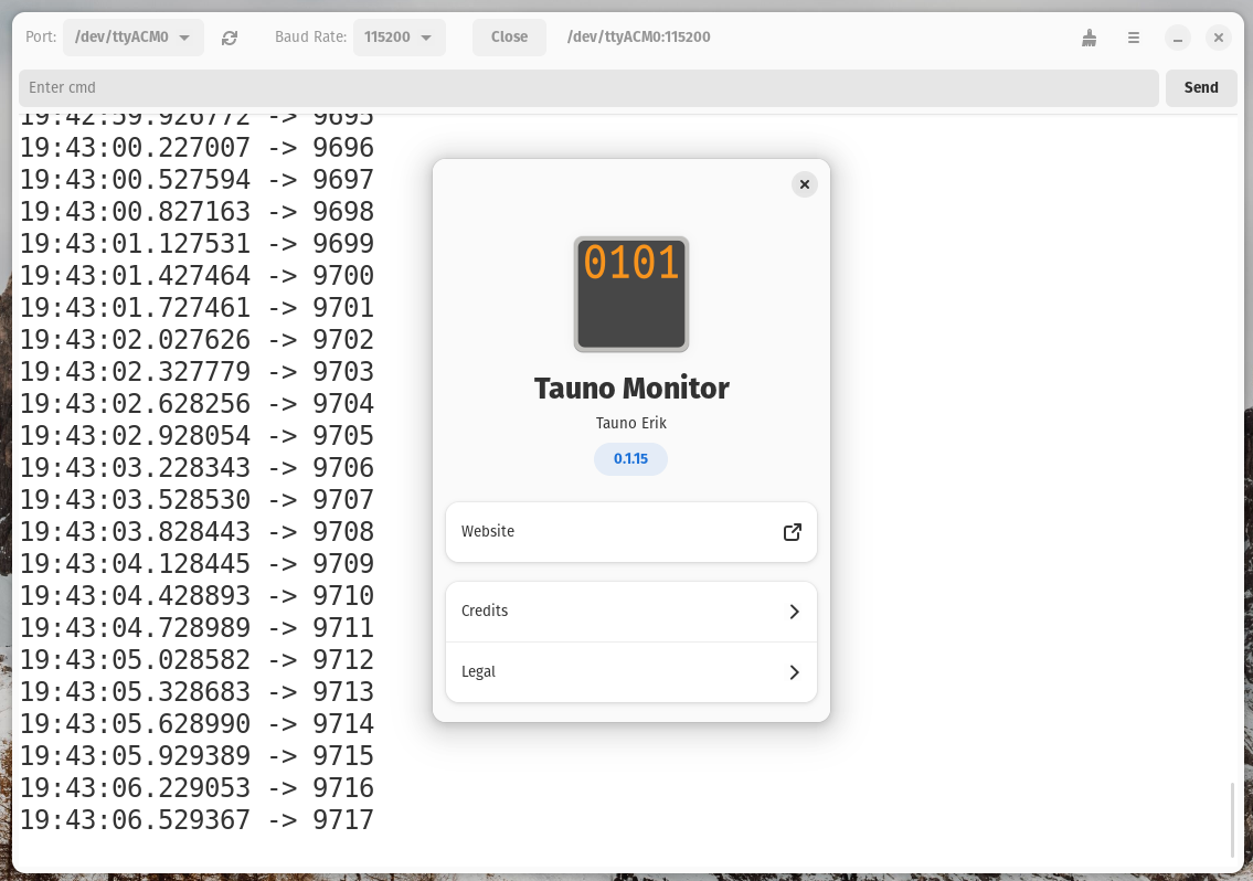
I have released a new version of the serial monitor application “Tauno Monitor” for Linux and added a “Clear” button and timestamps display option. The goal is to keep it simple and minimal.
The biggest PCB I’ve ever designed has arrived. And all RGB LEDs work as planned. Manufactured by JLCPCB. The diameter is about 260mm. It is still necessary to make the body and finish the firmware.
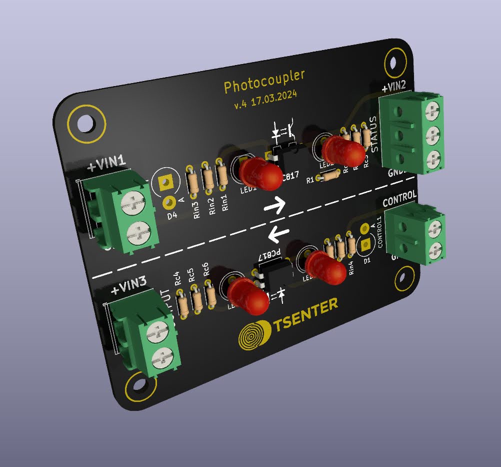
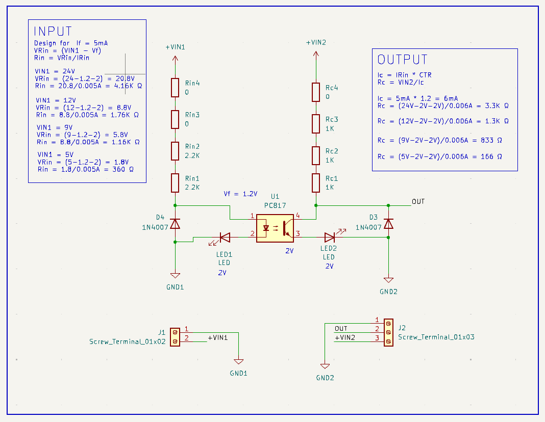
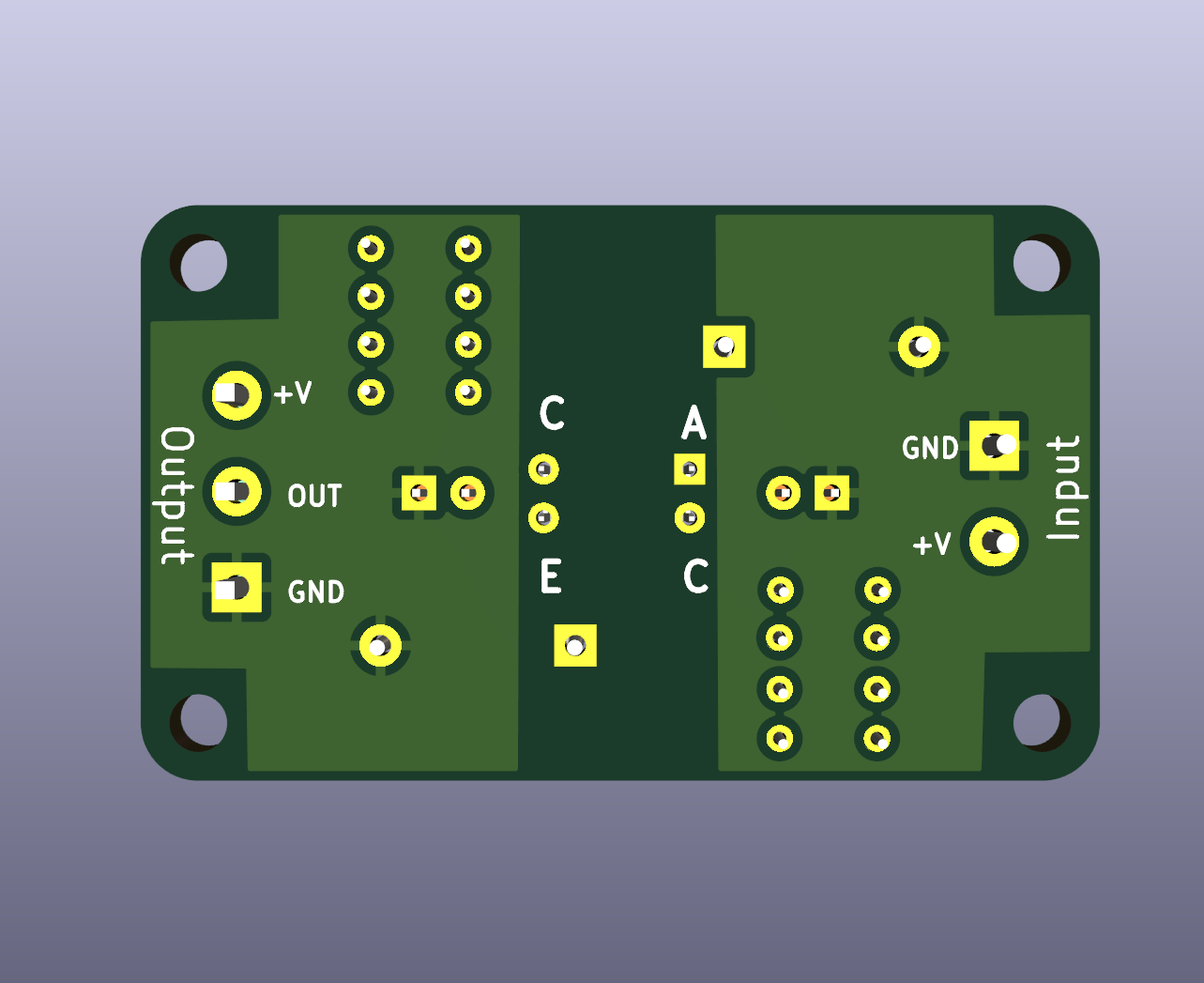
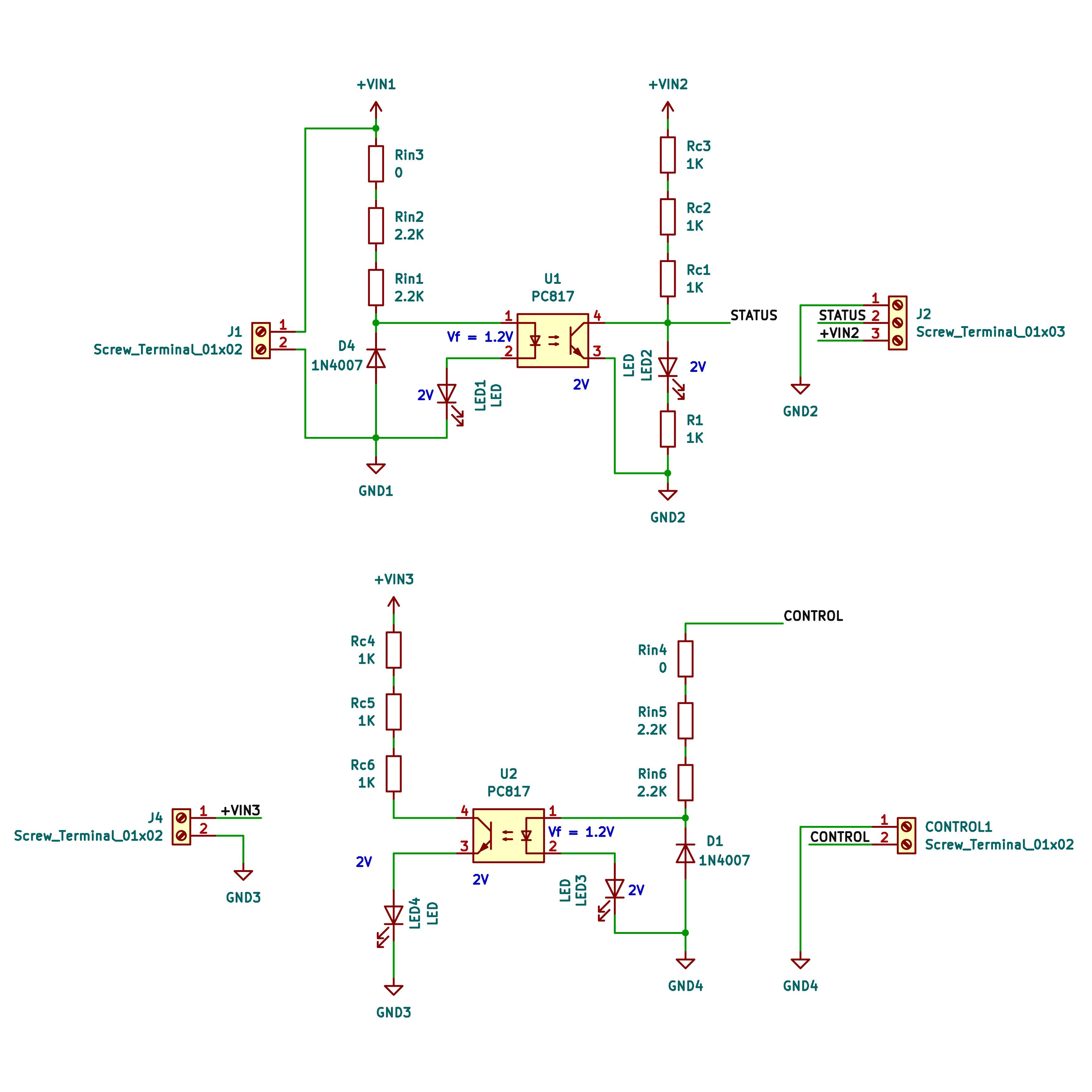
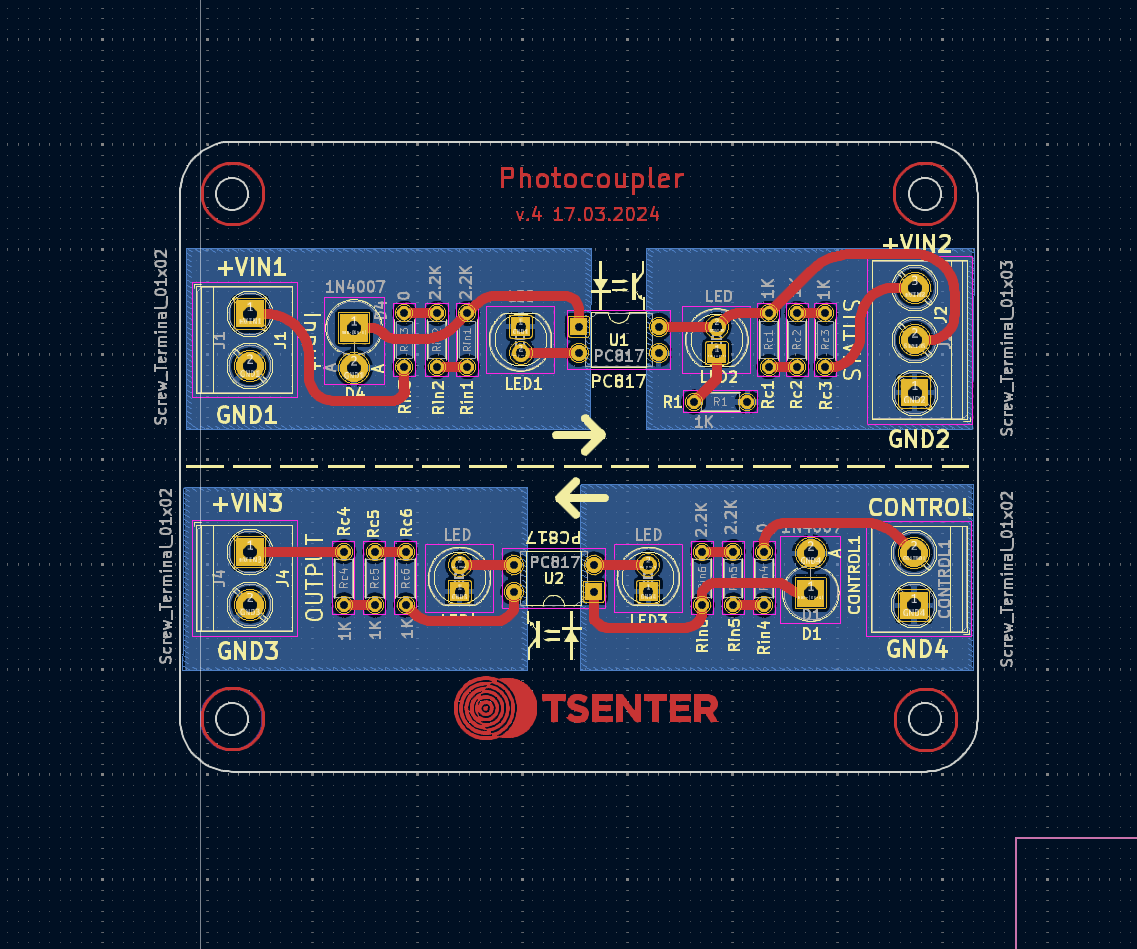
My photocoupler (optocoupler) board design. I added four resistor places to combine them with different input and output voltages. Also added a diode for reverse voltage protection. Does the output side need it? Any other suggestions?
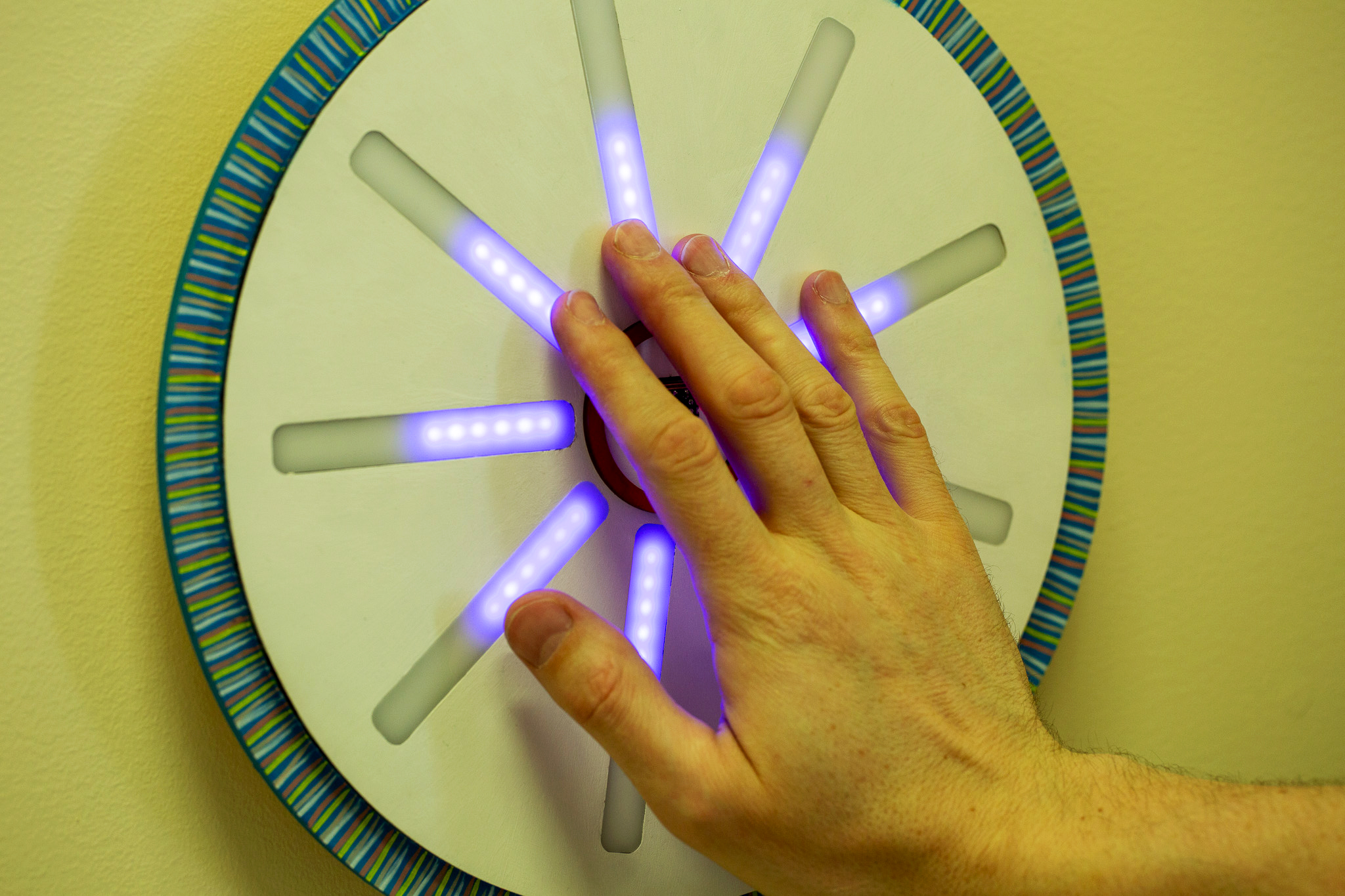
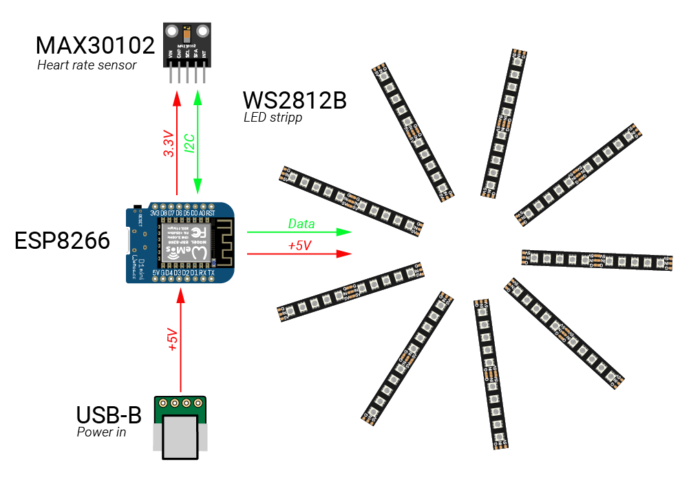
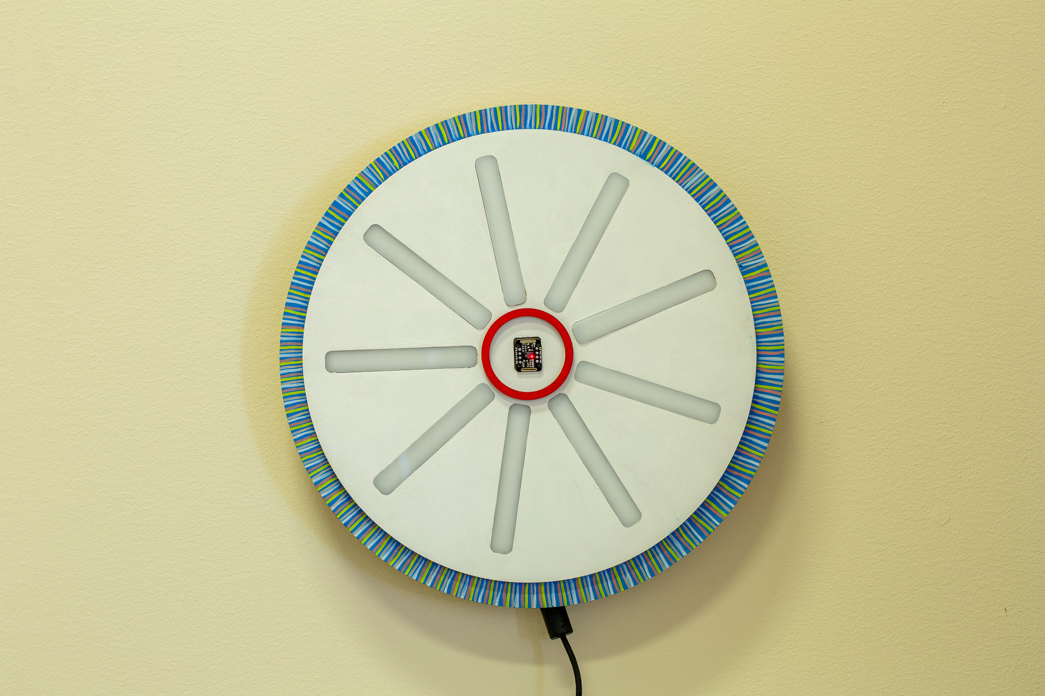
Andur mõõdab kehalt tagasi peegelduvat infrapuna (IR) kiirgust ja arvutab selle järgi pulsi sageduse. Samuti amplituudi, kuna on rõhk kõige kõrgem ja madalam, mida kajastab vastavalt põlevate LEDide hulk. IR väärtustest arvutatakse ka LEDide värv.