


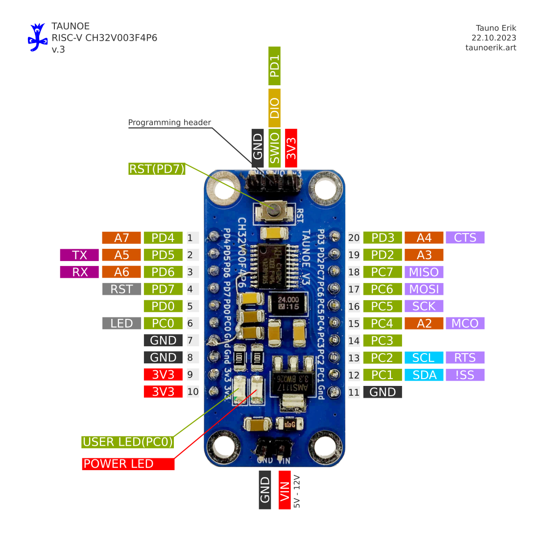
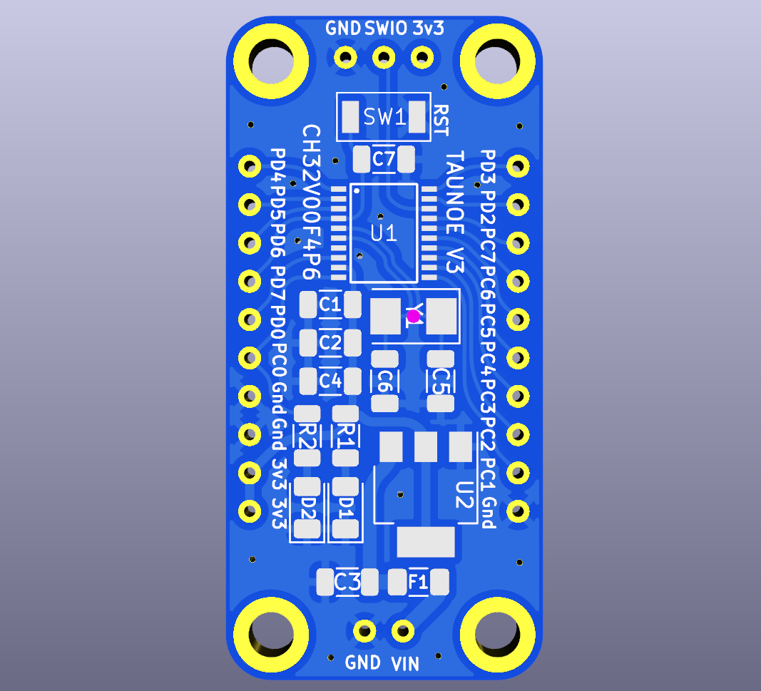
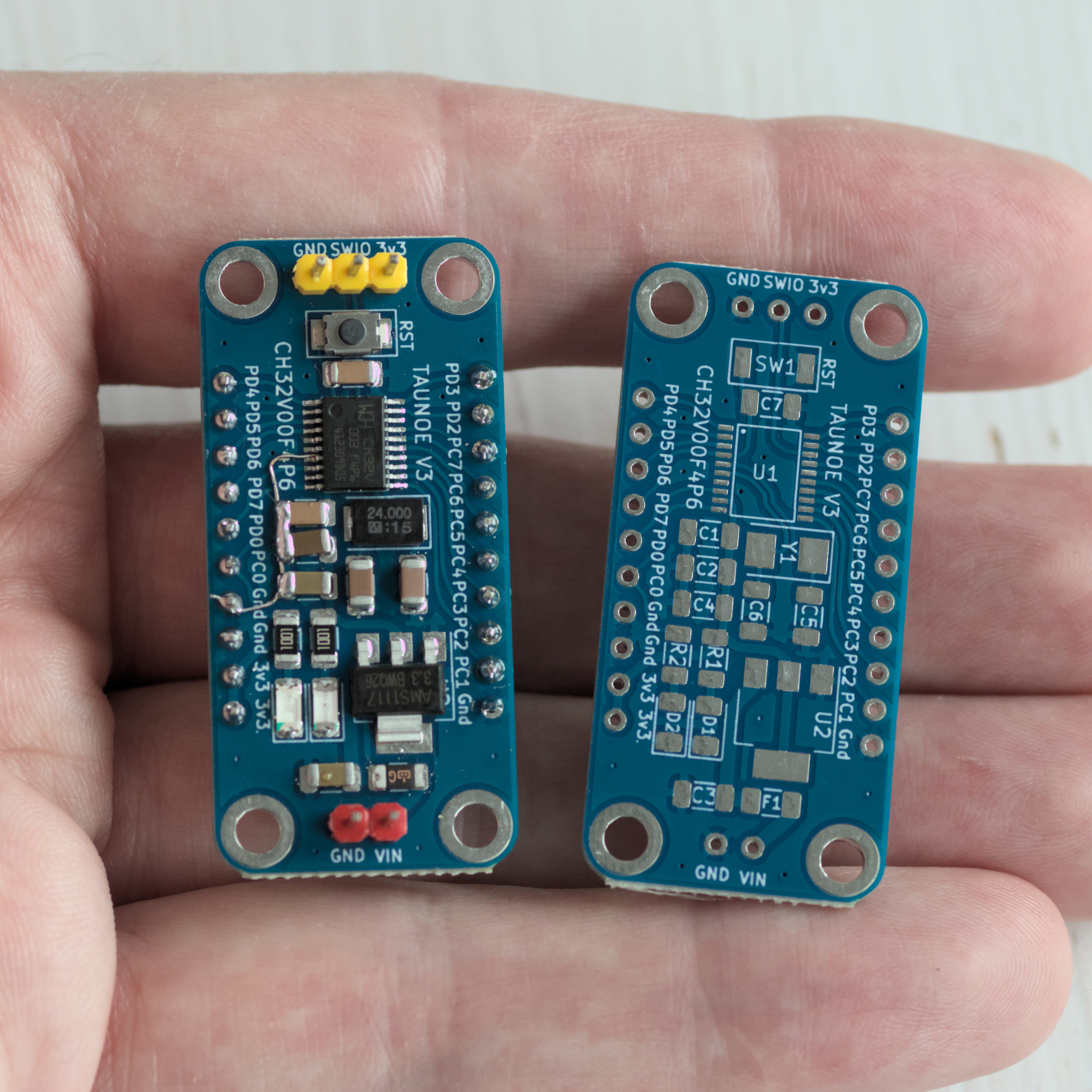
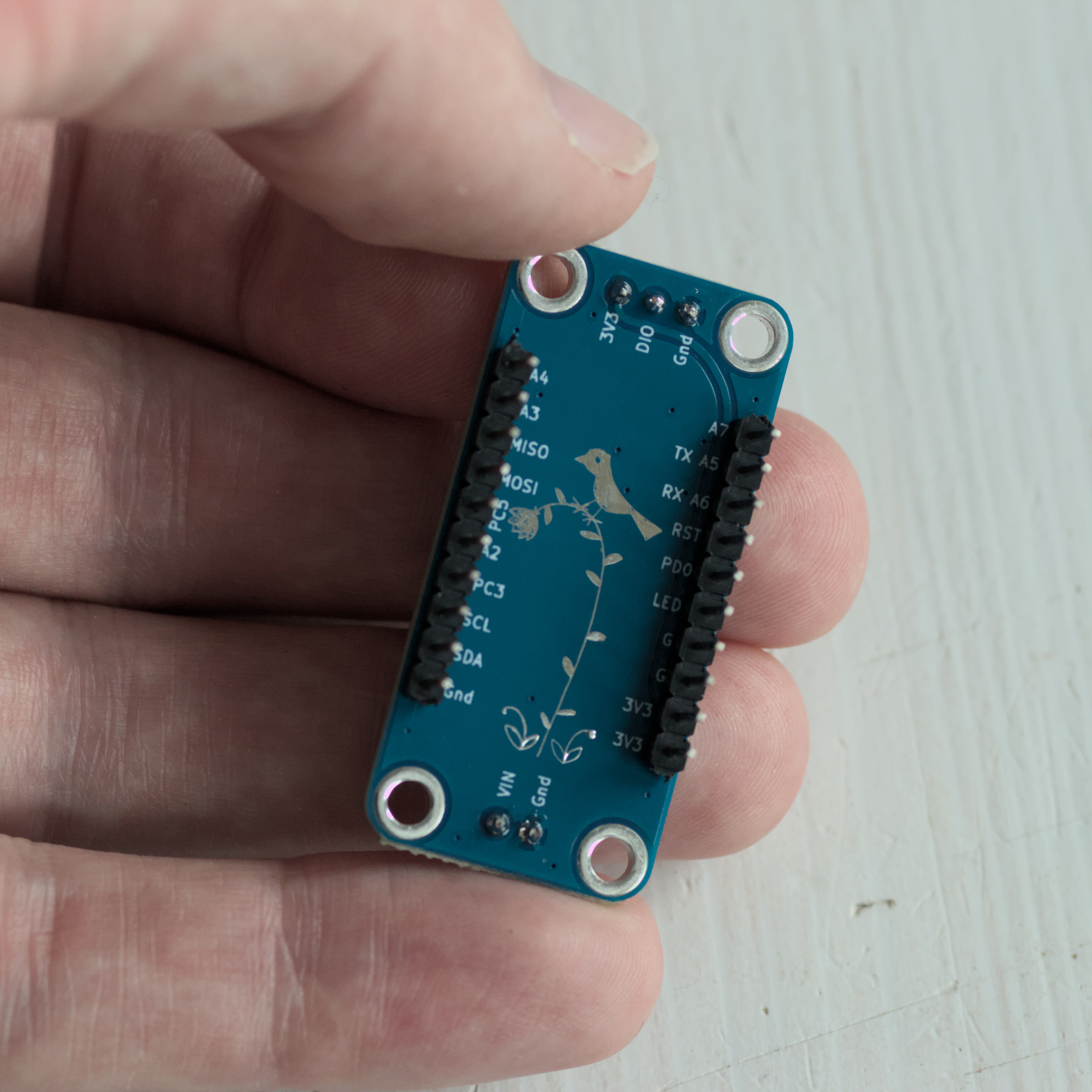
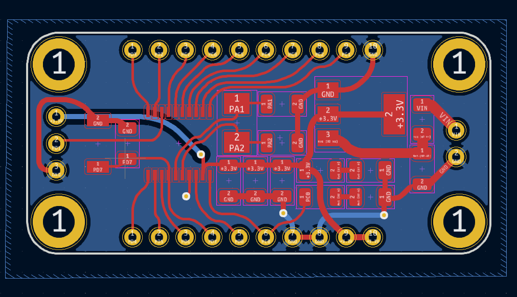
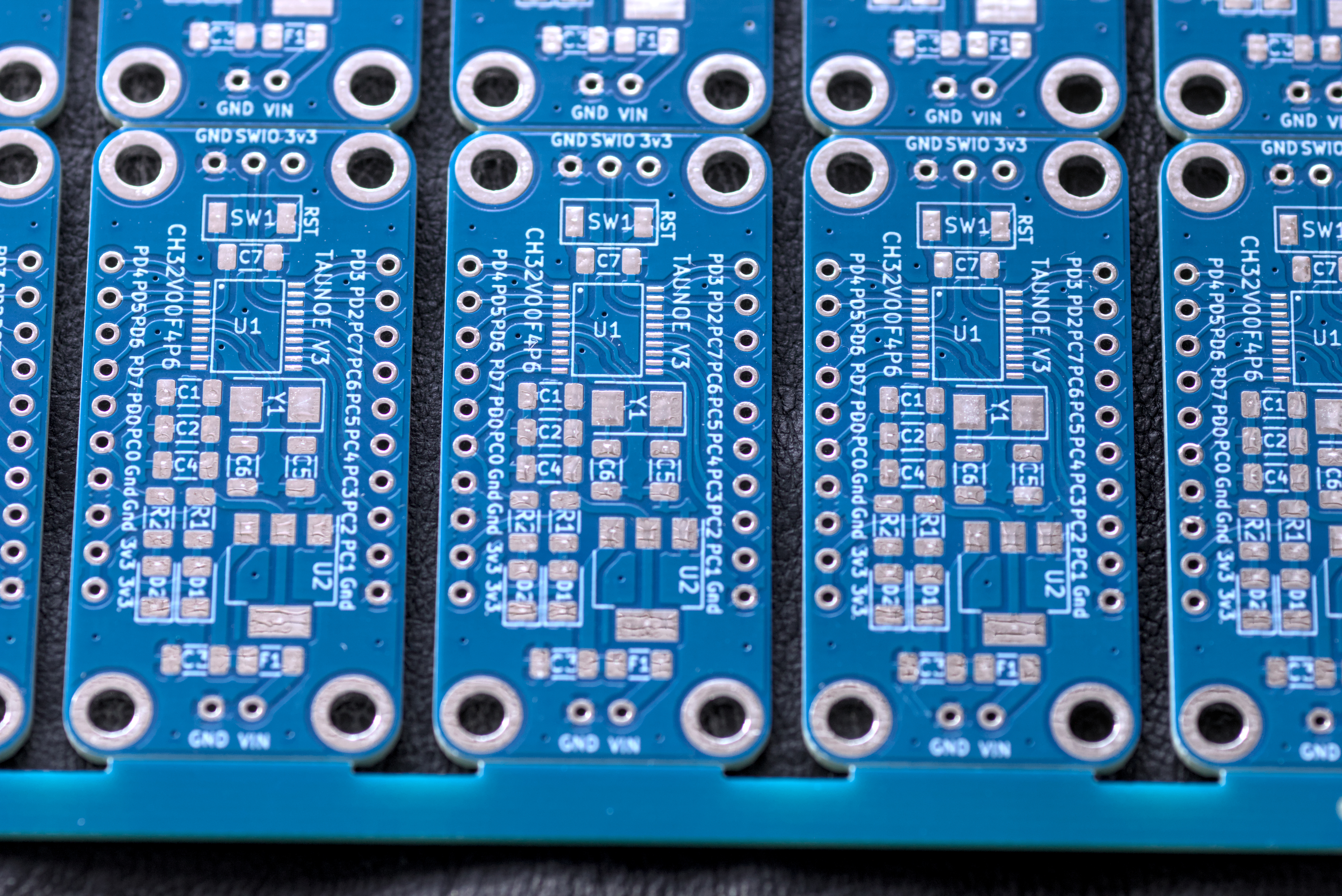
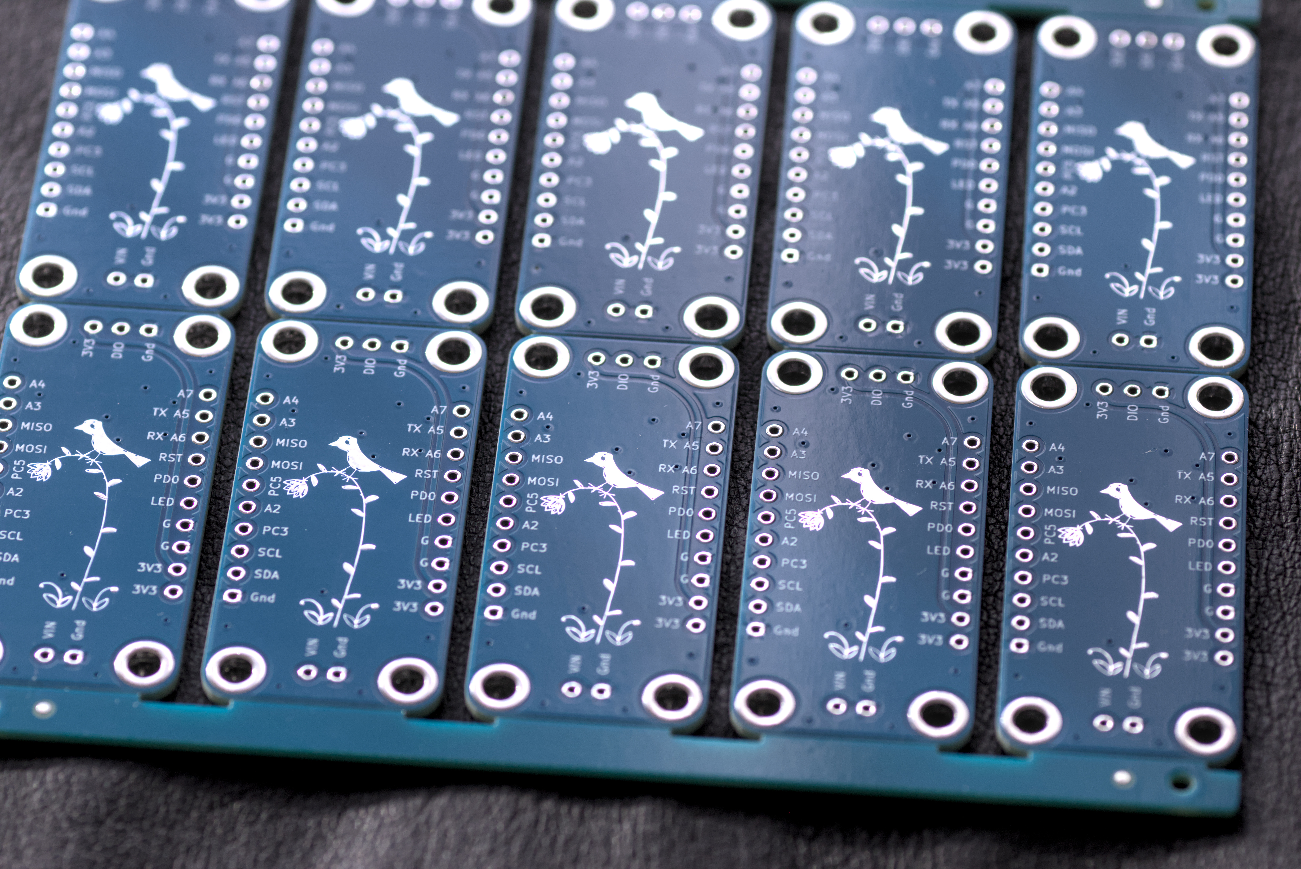
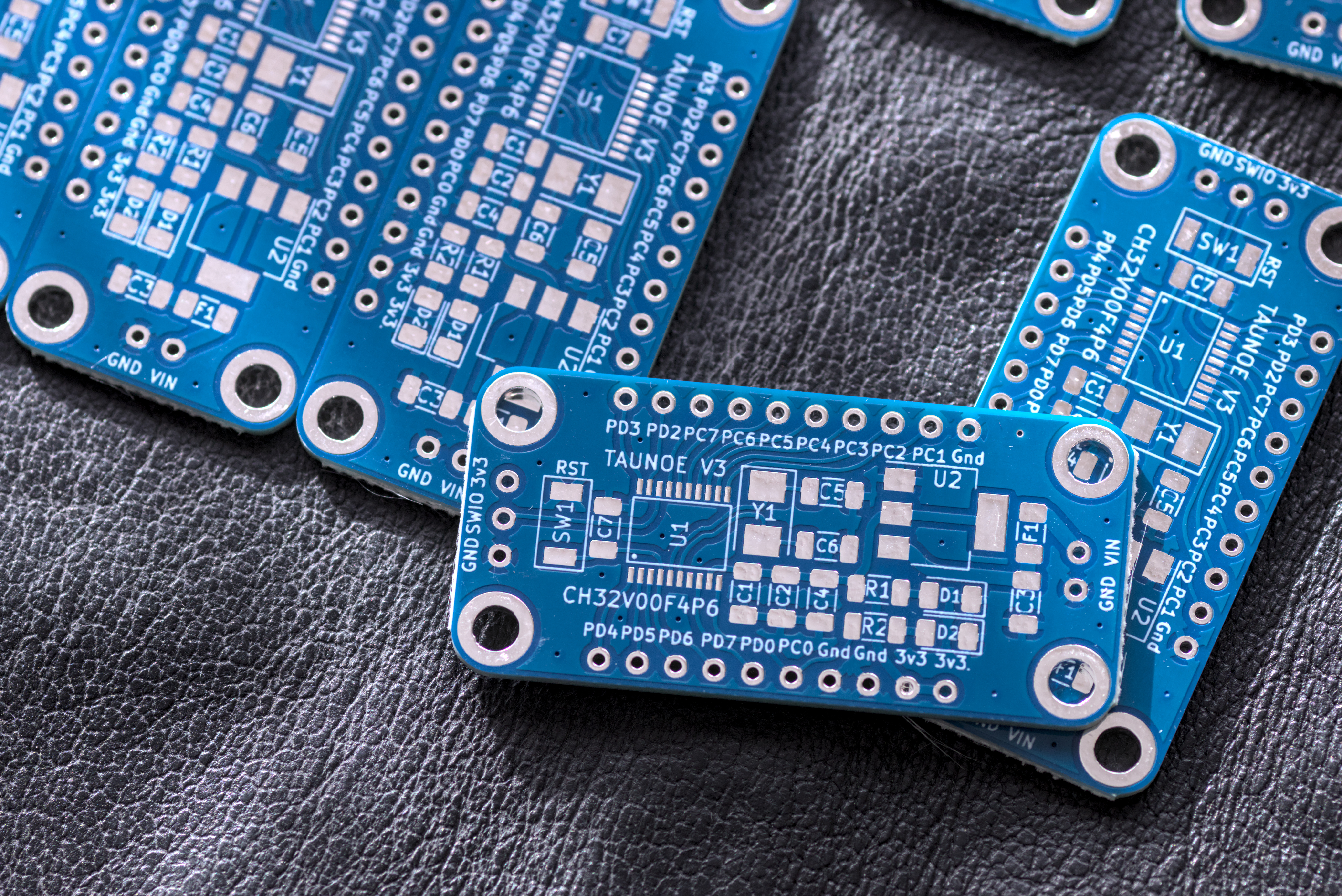
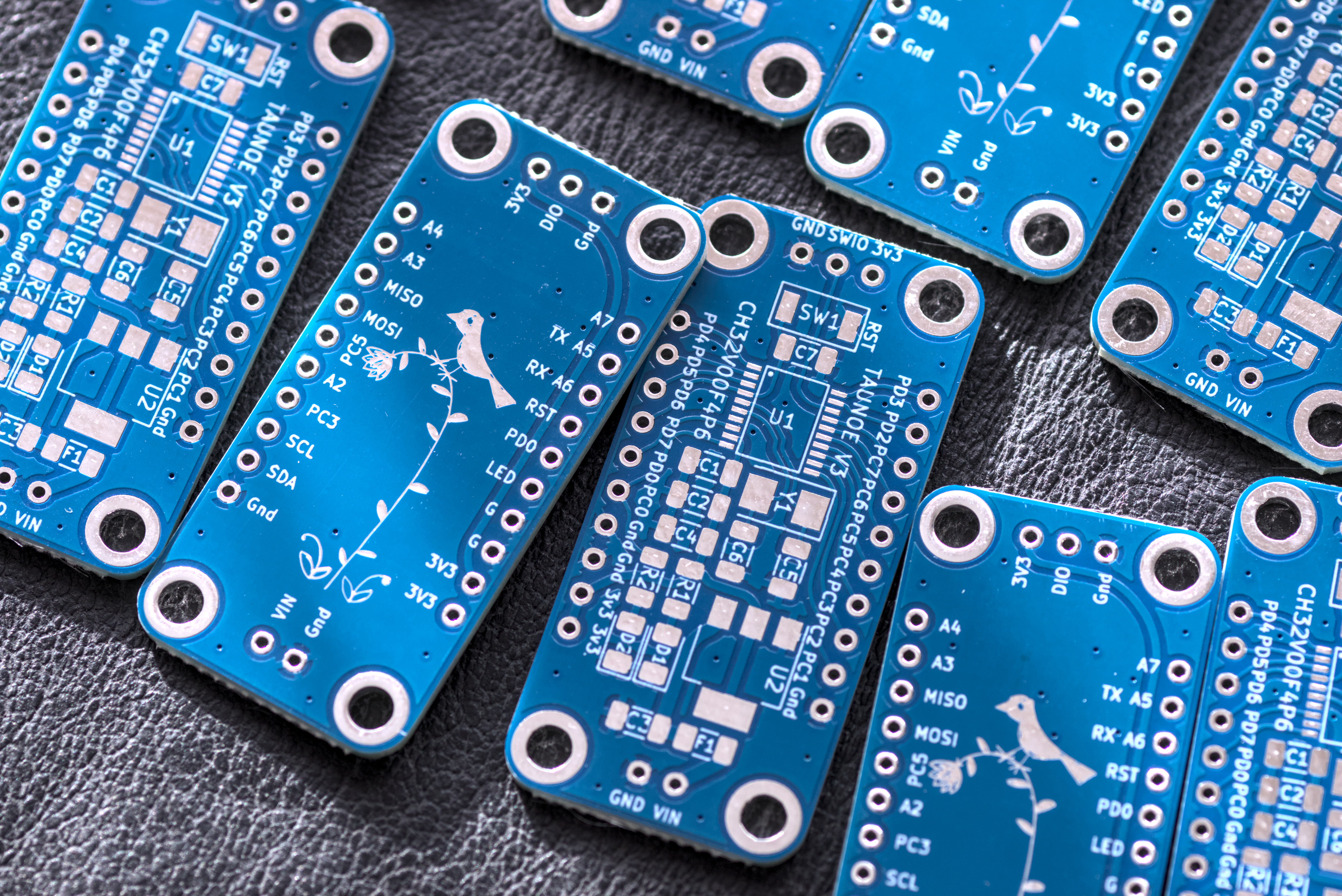
Finished my second version of the CH32V003F4P6 microcontroller board.

| Reference | Value | Footprint | Qty |
| C1,C7 | 0.1u | Capacitor_SMD:C_1206_3216Metric | 2 |
| C2,C3,C4 | 10u | Capacitor_SMD:C_1206_3216Metric | 3 |
| C5,C6 | 22pF | Capacitor_SMD:C_1206_3216Metric | 2 |
| D1,D2 | LED | LED_SMD:LED_1206_3216Metric | 2 |
| F1 | 500mA | Fuse:Fuse_1206_3216Metric | 1 |
| H1 | SWIO | Tauno_Footprint_Library:Header_th_3_2.54 | 1 |
| H2,H4 | ~ | — mixed values — | 2 |
| H3 | Header_left | Tauno_Footprint_Library:Header_th_10 | 1 |
| R1,R2 | 1K | Resistor_SMD:R_1206_3216Metric | 2 |
| SW1 | RST | Tauno_Footprint_Library:Push_button_smd_3x4x2_2pin | 1 |
| U1 | CH32V003F4P6 | Tauno_Footprint_Library:TSSOP20_0.65_ | 1 |
| U2 | AMS1117-3.3 | Package_TO_SOT_SMD:SOT-223-3_TabPin2 | 1 |
| Y1 | Crystal 25MHz | Crystal:Crystal_SMD_5032-2Pin_5.0x3.2mm | 1 |
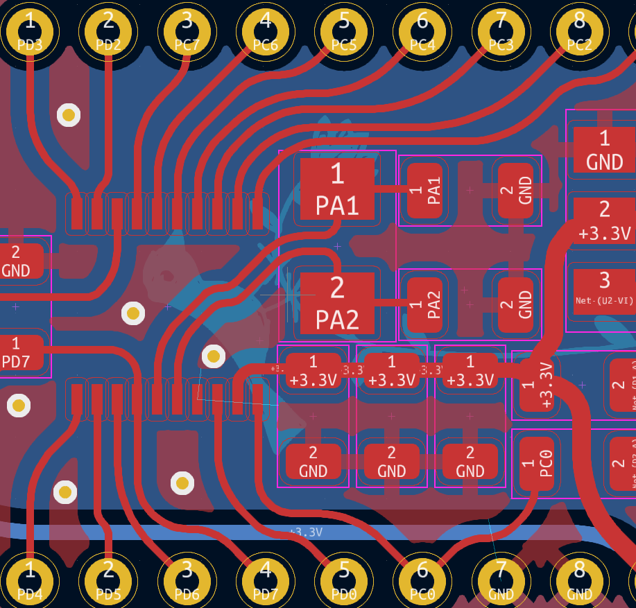
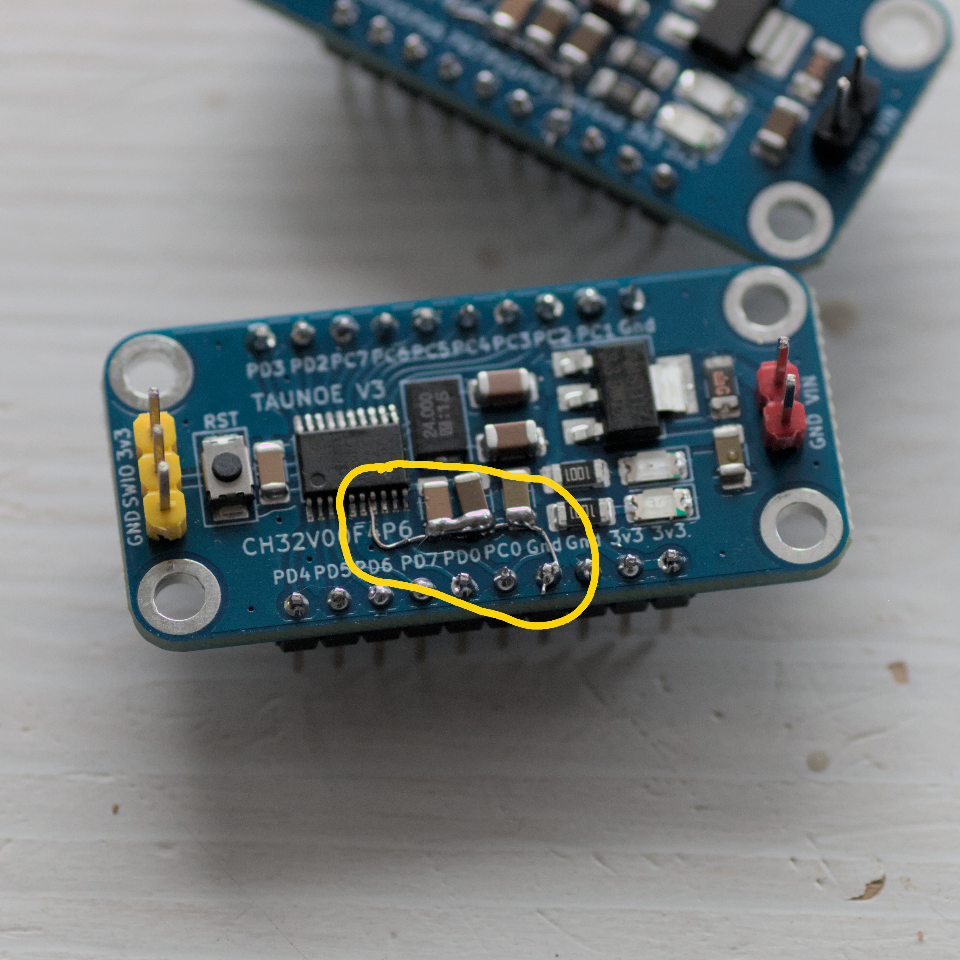
I rushed to order it and before it arrived I knew that there was a mistake where some ground pins were not connected. And I need to manually fix it.
I document my experiment code here. So I will find it next time when I need it.
/*
  Copyright 2023 Tauno Erik
  Started: 07.10.2023
  RC522 module
 */
#include <Arduino.h>
#include <Wire.h>
#include <SPI.h>
#include <Adafruit_PN532.h>
#include <Adafruit_NeoPixel.h>

// pins for SPI communication.
#define PN532_SCK    SCK
#define PN532_MOSI   MOSI
#define PN532_SS     SS
#define PN532_MISO   MISO
#define PN532_IRQ    22
#define PN532_RESET  21

Adafruit_PN532 nfc(PN532_SCK, PN532_MISO, PN532_MOSI, PN532_SS);

const int RGB_PIN = 2;
const int NUMPIXELS = 6;
Adafruit_NeoPixel pixels(NUMPIXELS, RGB_PIN, NEO_GRB + NEO_KHZ800);

int counter = 0;
uint8_t green_tag[7] = { 0x1D, 0xDE, 0xBC, 0xDC, 0x93, 0x00, 0x00 };
uint8_t   red_tag[7] = { 0x1D, 0x26, 0xBD, 0xDC, 0x93, 0x00, 0x00 };

const uint32_t OFF = pixels.Color(0, 0, 0);
const uint32_t GREEN = pixels.Color(0, 150, 0);
const uint32_t BLUE = pixels.Color(0, 0, 150);
const uint32_t RED = pixels.Color(150, 0, 0);

uint32_t pixels_colors[NUMPIXELS] = {OFF};

/*
Compare the two arrays
*/
bool is_equal(uint8_t array1[], uint8_t array2[]) {
  bool result = true;

  for (uint8_t i = 0; i < sizeof(array1); i++) {
    if (array1[i] != array2[i]) {
      result = false;
      break;
    }
  }
  return result;
}

void add_color(uint32_t new_color) {
  // move elemnts to right one step
  for (int i = NUMPIXELS; i > 0; i--) {
    pixels_colors[i] = pixels_colors[i-1];
  }
  pixels_colors[0] = new_color;
}

void setup(void) {
  Serial.begin(115200);
  /*
  while (!Serial) {
    delay(10);
  }
  */
  Serial.println("Hello!");

  pixels.begin();
  pixels.show();             // Turn OFF all pixels ASAP
  pixels.setBrightness(50);  // Set BRIGHTNESS to about 1/5 (max = 255)

  nfc.begin();

  uint32_t versiondata = nfc.getFirmwareVersion();

  if (!versiondata) {
    Serial.print("Didn't find PN53x board");
    while (1) {
      // halt
    }
  }

  // Got ok data, print it out!
  Serial.print("Found chip PN5");
  Serial.println((versiondata>>24) & 0xFF, HEX);
  Serial.print("Firmware ver. ");
  Serial.print((versiondata>>16) & 0xFF, DEC);
  Serial.print('.');
  Serial.println((versiondata>>8) & 0xFF, DEC);

  // Set the max number of retry attempts to read from a card
  // This prevents us from waiting forever for a card, which is
  // the default behaviour of the PN532.
  nfc.setPassiveActivationRetries(0xFF);

  Serial.println("Waiting for an ISO14443A card");
}

void loop(void) {
  pixels.clear();  // Set all pixel colors to 'off'
  boolean success;

  uint8_t uid[] = { 0, 0, 0, 0, 0, 0, 0 };  // Buffer to store the returned UID
  // 4 or 7 bytes depending on ISO14443A card type
  // ntag 7 bytes
  uint8_t uid_length;

  // Wait for an ISO14443A type cards (Mifare, etc.).  When one is found
  // 'uid' will be populated with the UID, and uidLength will indicate
  // if the uid is 4 bytes (Mifare Classic) or 7 bytes (Mifare Ultralight)
  success = nfc.readPassiveTargetID(PN532_MIFARE_ISO14443A, &uid[0], &uid_length);

  if (counter > NUMPIXELS) {
    counter = 0;
  }

  if (success) {
    Serial.println("Found a card!");
    Serial.print("UID Length: ");
    Serial.print(uid_length, DEC);
    Serial.println(" bytes");

    Serial.print("UID Value: ");
    for (uint8_t i=0; i < uid_length; i++) {
      Serial.print(" 0x");
      Serial.print(uid[i], HEX);
    }
    Serial.println("");

    if (is_equal(green_tag, uid) && uid_length == 7) {
      Serial.println("green tag");
      add_color(GREEN);
    } else if (is_equal(red_tag, uid) && uid_length == 7) {
      Serial.println("red tag");
      add_color(RED);
    } else {
      Serial.println("unknown tag");
      add_color(OFF);
    }


    counter++;
    for (int i = 0; i < NUMPIXELS; i++) {
      pixels.setPixelColor(i, pixels_colors[i]);
    }
    pixels.show();
    delay(500);  // slowdown

  } else {
    // PN532 probably timed out waiting for a card
    // Serial.println("Timed out waiting for a card");
    Serial.println("---");
  }
}
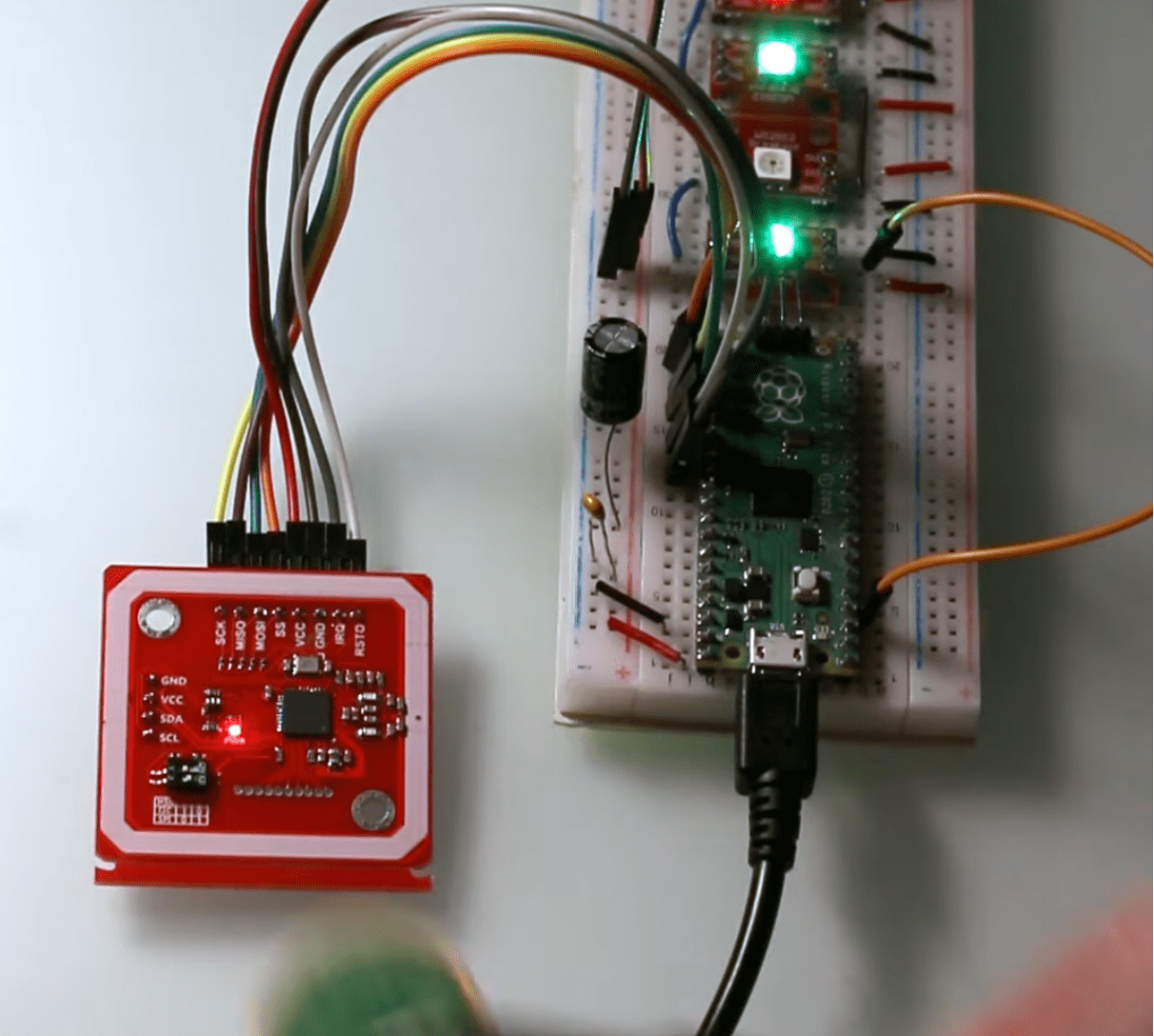
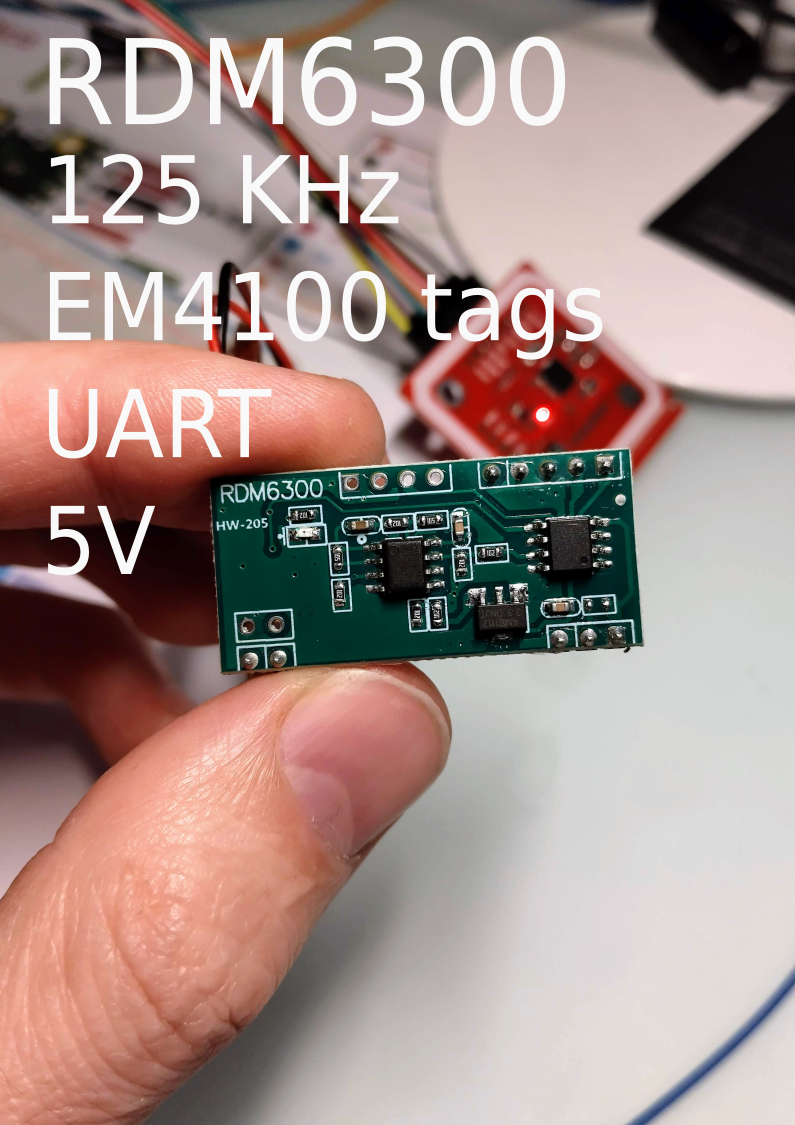
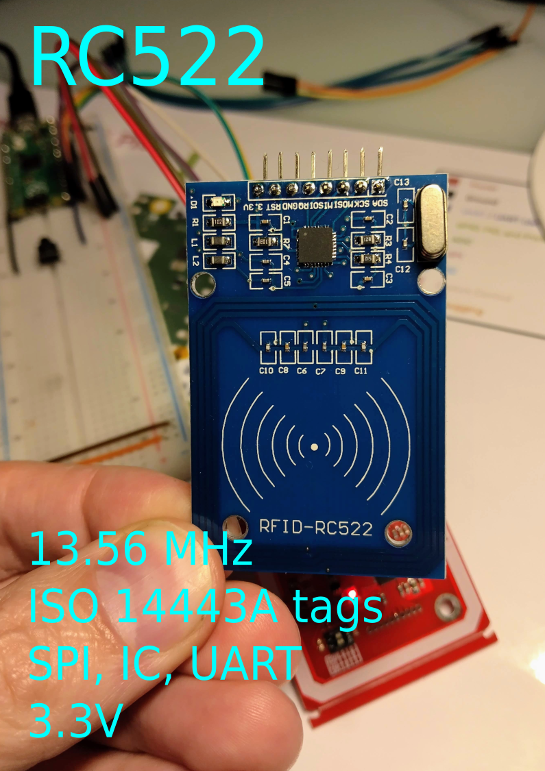
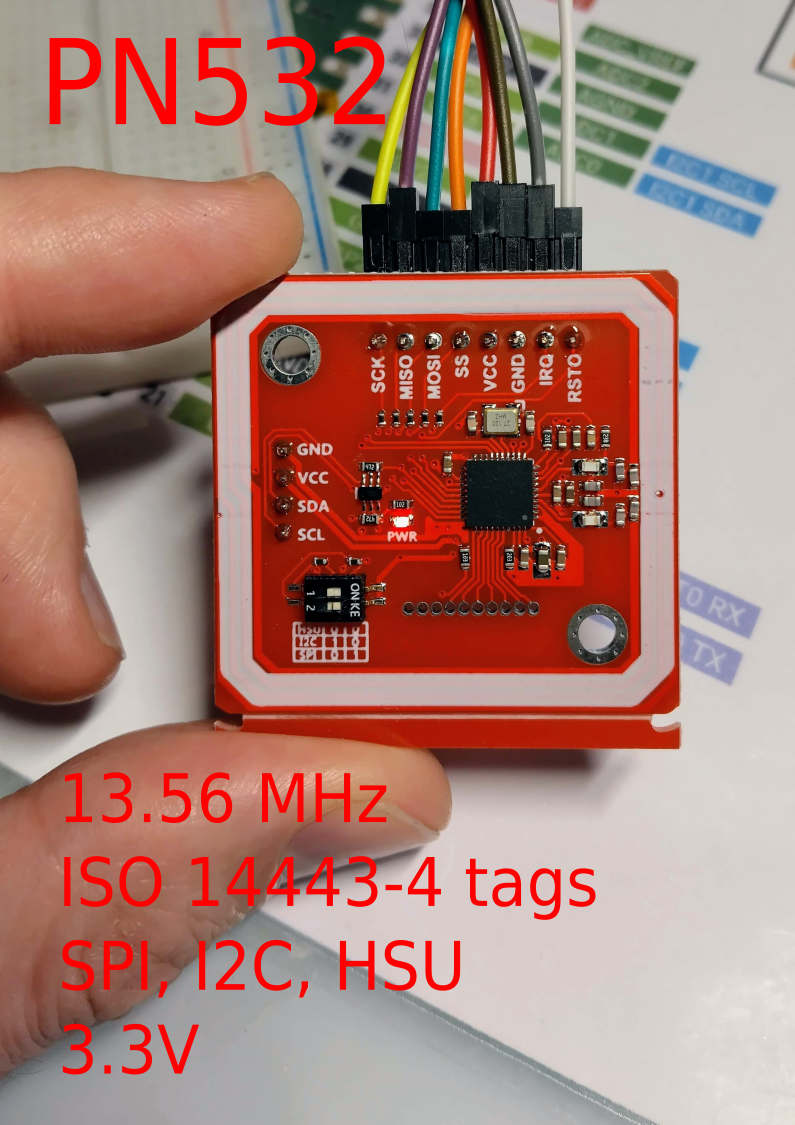
I bought some RFID readers and plan to experiment with them soon. Here are my notes.
Arduino libraries:
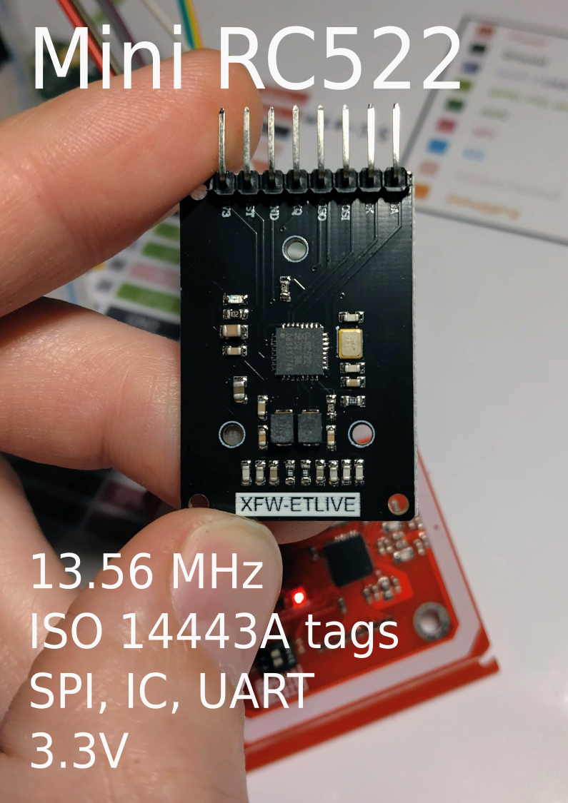
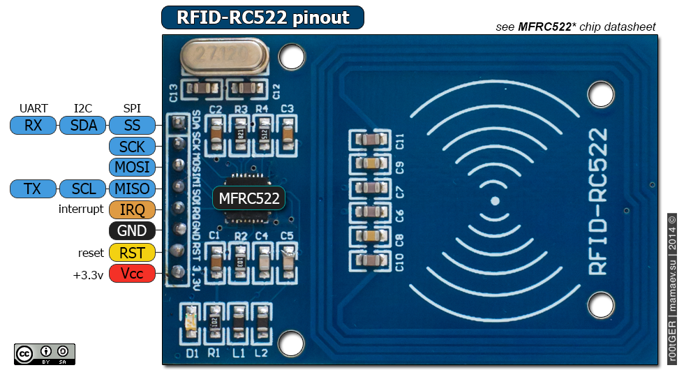
Can be programmed to generate an interrupt (IRQ), allowing the module to alert us when a tag approaches it.
Arduino libraries:
| RS522 pin | Pi Pico pin |
| MISO | GPIO16 |
| SS | GPIO17 |
| SCK | GPIO18 |
| MOSI | GPIO19 |
| 3.3V | 3.3V |
| GND | GND |
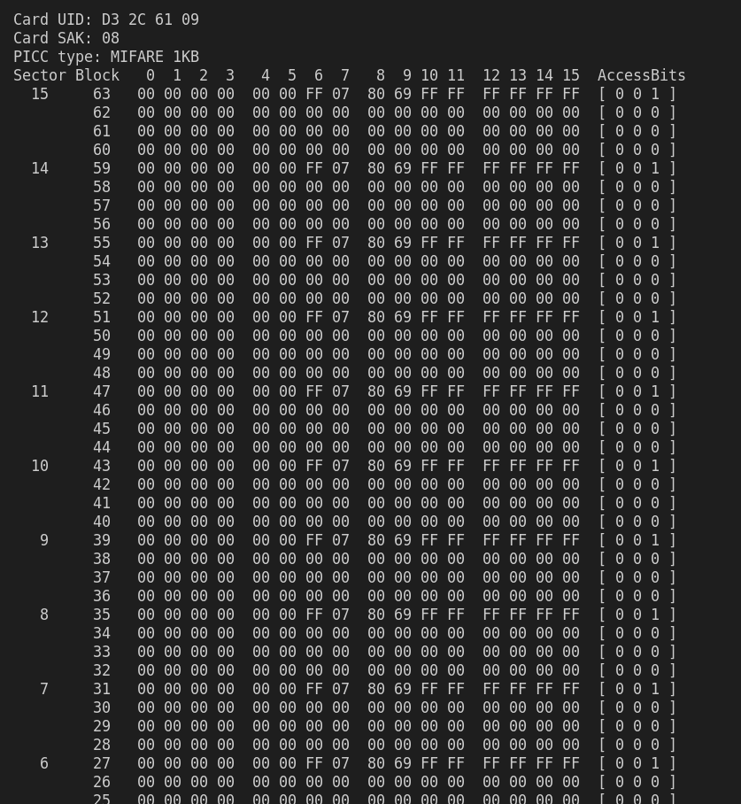
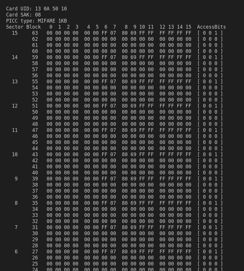
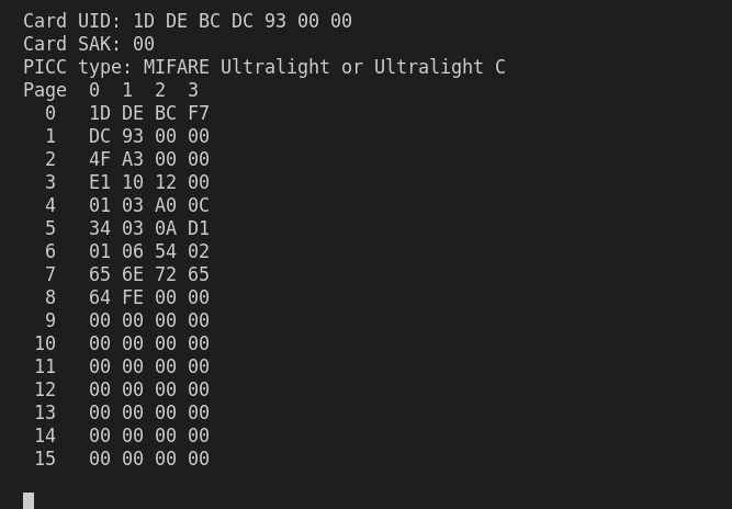
Dump info examples:
Arduino libraries:
The tag’s 1K memory is organized into 16 sectors (from 0 to 15).
Each sector is divided into 4 blocks (blocks 0 to 3).
Each block can store 16 bytes of data (from 0 to 15).
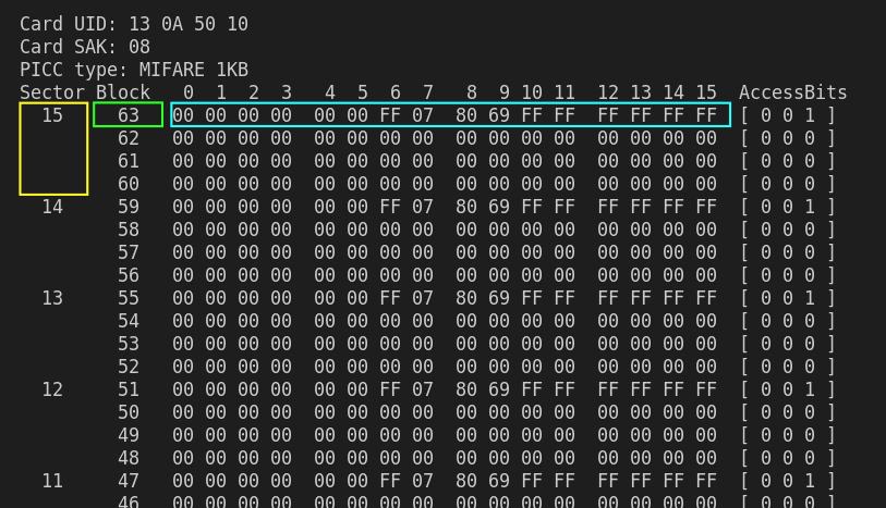
The last block of each sector is called a Sector Trailer. It contains information called Access Bits that provide read and write access to the remaining blocks in the sector. This means that only 3 blocks of each sector (Blocks #0, #1 and #2) are actually writable, in other words only 48 bytes per sector are available for use.
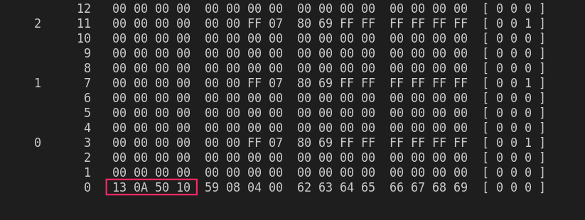
Block #0 of Sector #0 is called Manufacturer Block which contains IC Manufacturer data and a Unique Identifier (UID).


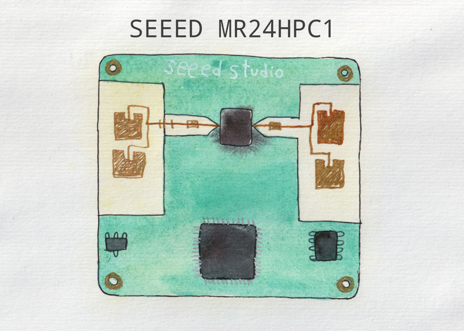
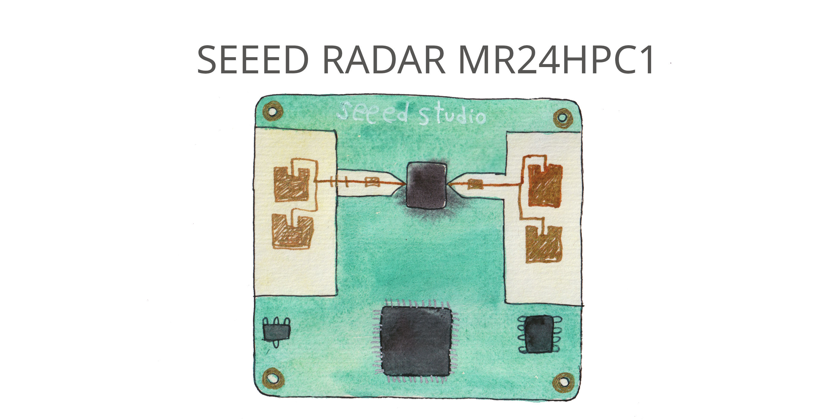
In one project I needed to use Seeed Studio mmWave radar MR24HPC1, and to better understand how it works and what it does, I ended up writing my own Arduino library for this sensor. Learned a lot.
It has two modes: simple and advanced.
| Available methods | SIMPLE | ADVANDCED |
|---|---|---|
| reset() | + | + |
| get_mode() | + | + |
| get_heartbeat() | + | + |
| get_activity() | + | |
| get_direction() | + | |
| get_motion() | + | |
| get_presence() | + | |
| get_motion_energy() | + | |
| get_motion_speed() | + | |
| get_motion_distance() | + | |
| get_static_energy() | + | |
| get_static_distance() | + | |
| get_initialization_status() | + | |
| get_time_for_entering_no_person_state() | + | + |
| get_motion_trigger_time() | + | |
| get_motion_to_static_time | + | |
| get_static_trigger_limit() | + | |
| set_static_limit() | + | |
| set_motion_limit() | + | |
| set_static_threshold | + | |
| set_motion_threshold | + | |
| set_absence_trigger_time | + |
My Arduino library for Seeed MR24HPC1 24GHz radar is in GitHub.
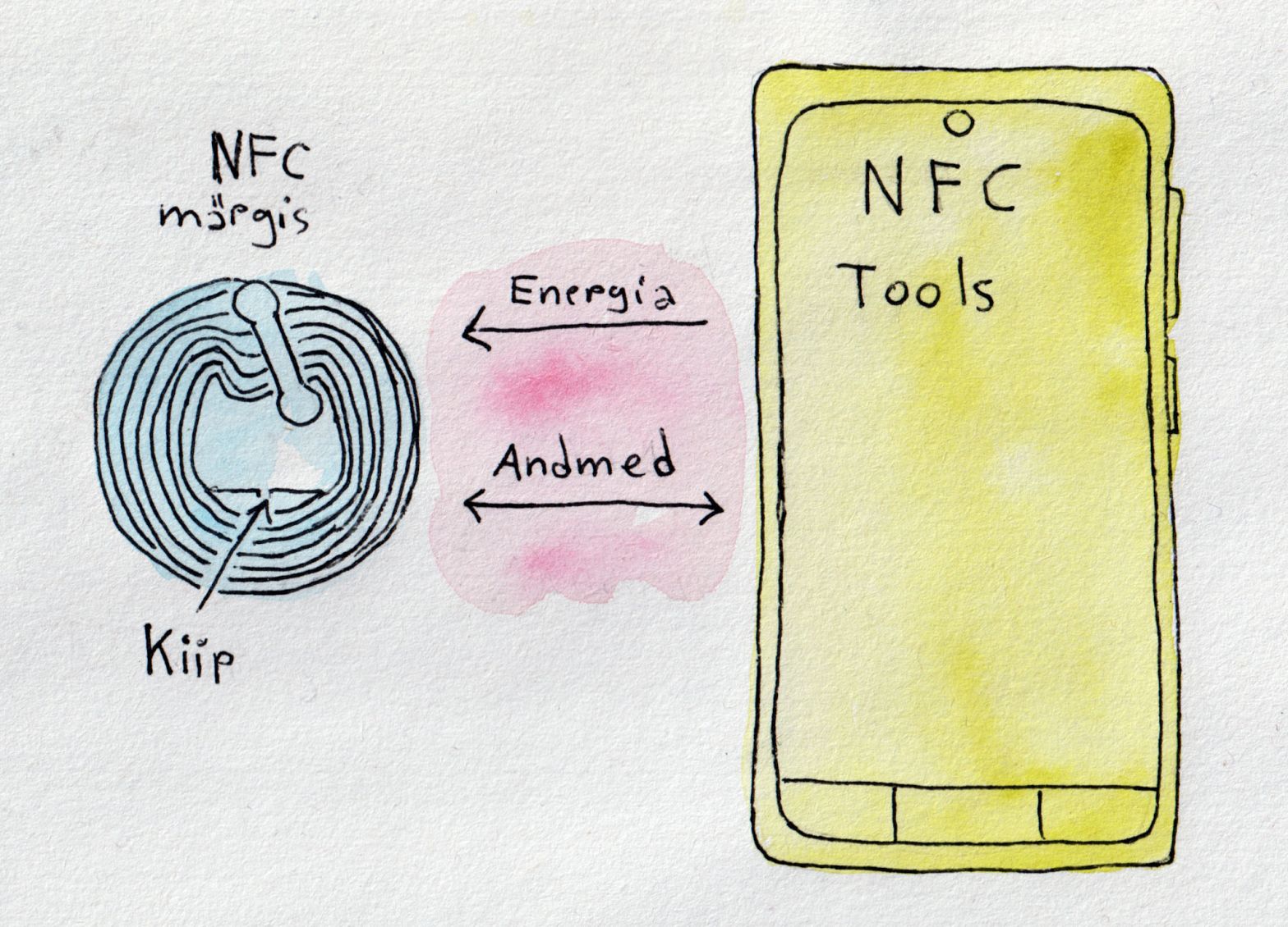
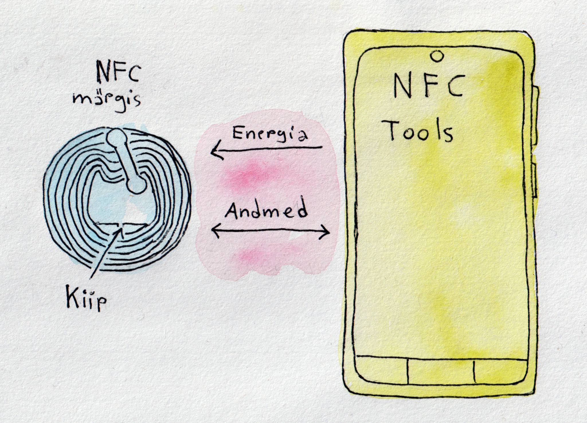
Near Field Communication ehk lähiväljaside on juhtmevabade tehnoloogiate kogum, mis nõuab ühenduse loomiseks 4 cm või väiksemat vahemaad. NFC võimaldab jagada andmeid NFC-sildi ja telefoni või kahe mobiiltelefoni vahel.
Töötamiseks peavad olemad NFC-sildi ja telefoni antennid lähestikku, et tekkiks vastastikune induksioon. Kus voolumuutus aktiivses seadmes (mobiil telefon) kutsub esile elektromootoorjõu passiivses seadmes (NFC-silt).
NFC-märgised võivad olla erineva kompleksusega. Lihtsamad võimaldavad lugemist ja kirjutamist. Keerulisemad pakuvad matemaatilisi toiminguid ja krüptograafilist riistvara. Kõige keerulisemad võivad käituda peaaegu nagu väiksed arvutid.
Andmed NFC sildil võivad olla kirjutatud erinevas vormingus aga kõige levinum on NFC Forumi poolt arendatud standard NDEF (NFC Data Exchange Format).
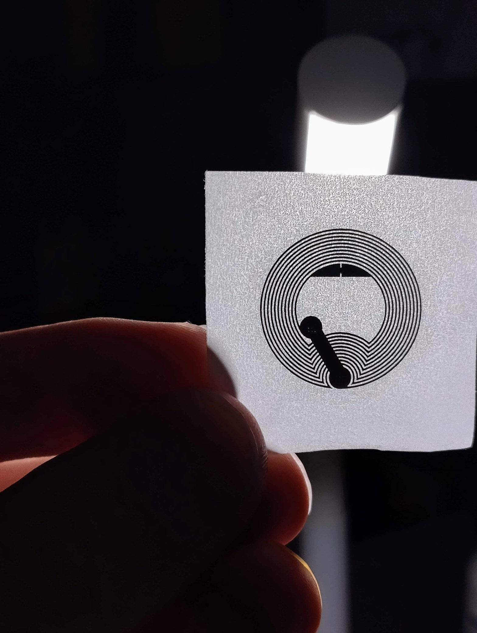
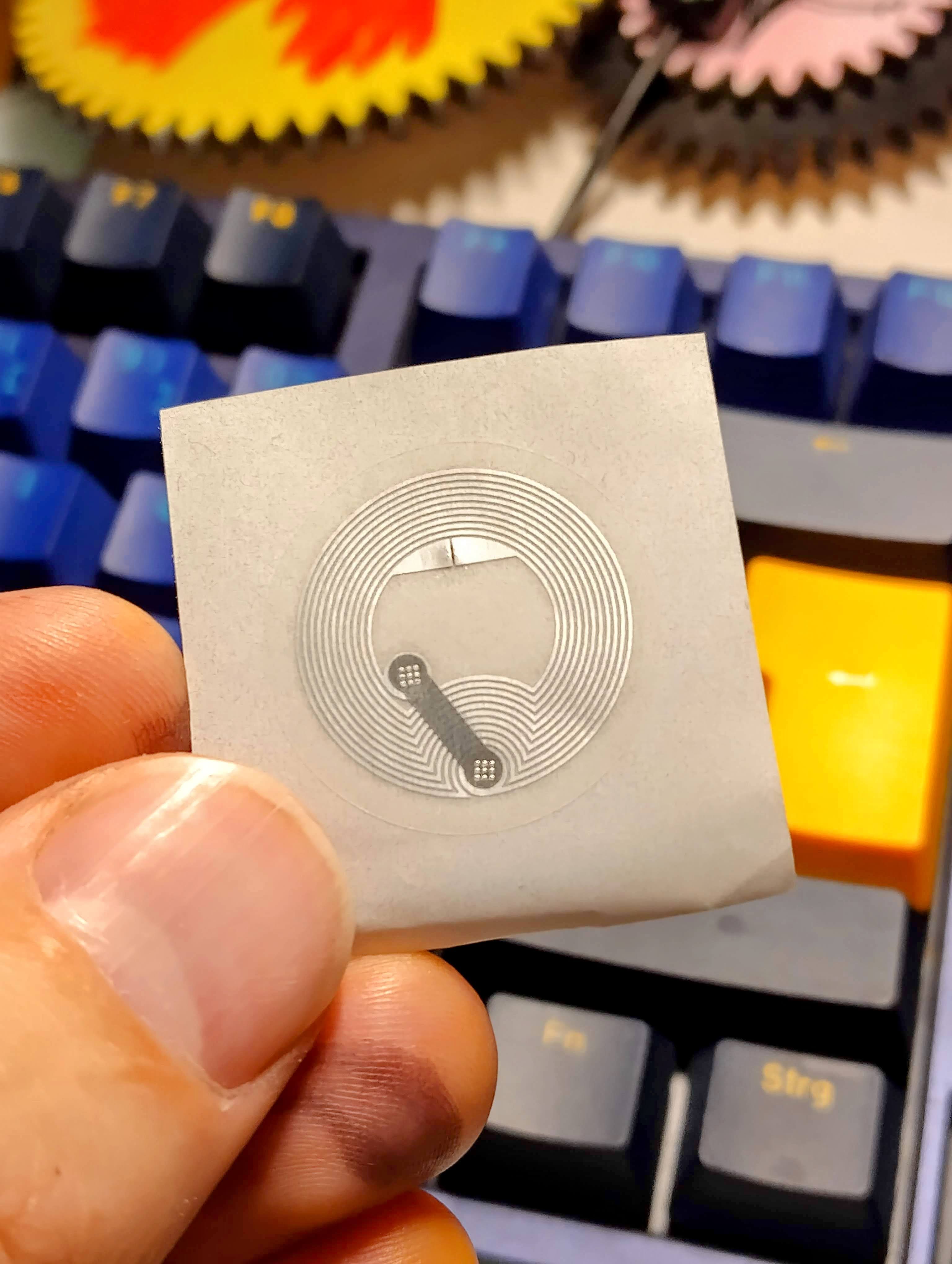
NTAG® on NXP ® pool välja arendatud NFC märgised, tegelikult märgise sees olevad kiibid, mis on mõeldud laiaotstabelisteks tavatarbija kasutamiseks: jaemüügis, mängudes, tarbeelektroonikas, trükimeedia nutikad reklaamid, toodete autentimine, riiulisildid, visiitkaardid, WiFi sidumiseks jne. Töötavad kõikide telefonidega, kus on NFC olemas. Kiibi paksus on 75 μm. Ühe kleebise paksus on u 0.27 millimeetri. Märgisel olevat sisu (andmeid) saab korduvalt muuta ja ülekirjutada. Võimalusel saab lisada kirjutuskaitse, pärast mida andmeid enam ei saa muuta. Märgistel puudub oma energia allikas (patarei). Energia kantakse kiibi lugemise käigus üle raadiolainete kaudu (sagedusel 13,56 MHz). Töökaugus sõltub väljatugevusest ja antenni suurusest/kujust. Saab lisada paroolikaitse (NTAG 215 ja NTAG 216).
Üks võimalus ongi vaadata NFC Forum Tage, kui väikseid kontaktivabasid mälukaarte. Millega andme vahetus toimub NDEF (NFC Data Exchange Format) kirjetena. NFC Forum on määratlenud viis erinevat Tagi tüüpi (Type1-5).
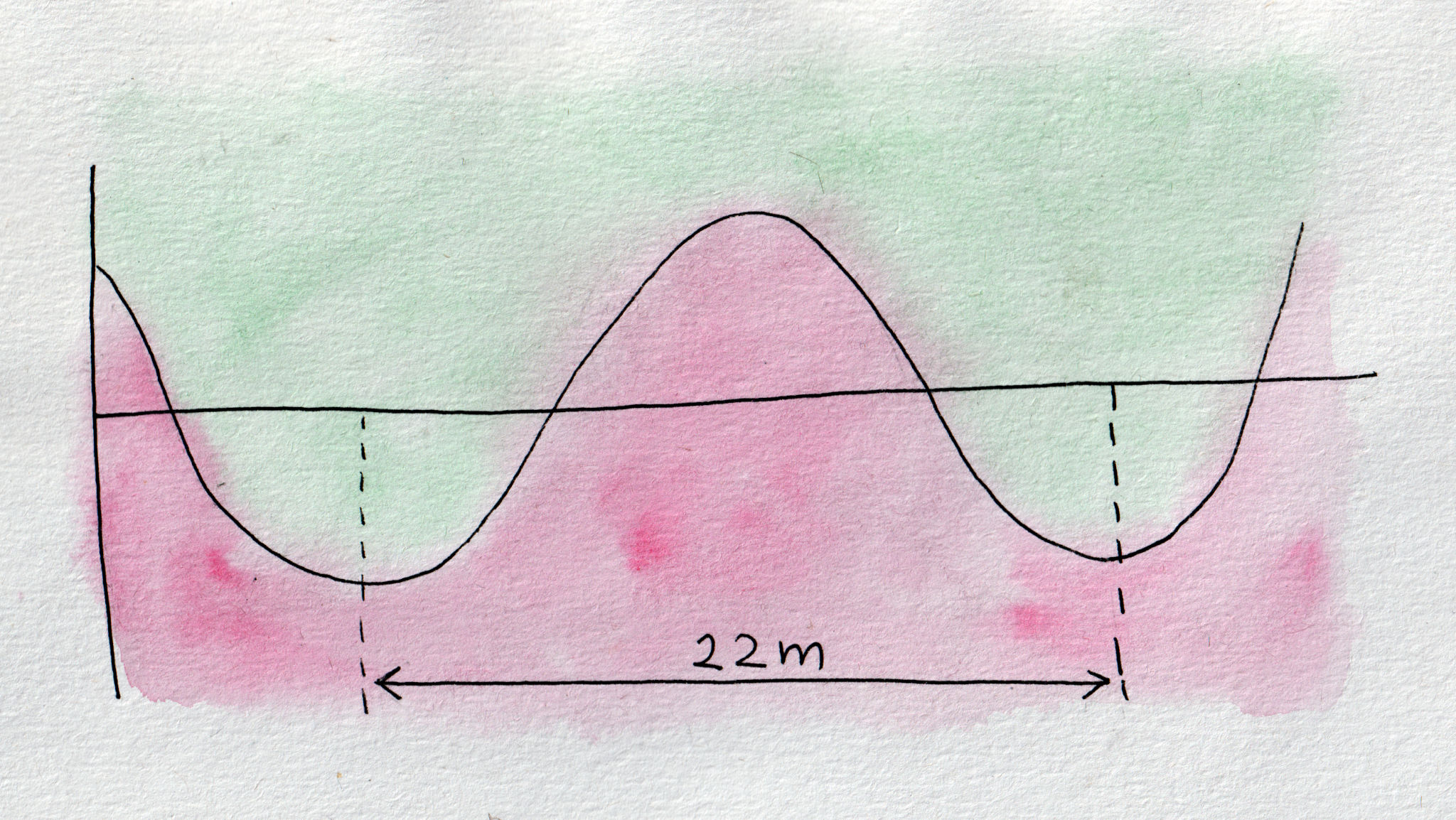
Sagedusel 13,56 MHz lainepikkus on u 22m.
Vastavad täielikult NFC Forum Type 2 Tag ja ISO/IEC14443 Type A standardile. Märgiseid saab kuni 100 000 korda ülekirjutada ja lubatakse, et andmed säilivad vähemal 10 aastat.
Andmeedastus kiirus 106 kbit/s.
Igal märgisel on oma unikaalne 7-baidine ID kood.
On erineva mälu suurusega:
| Nimi | Vaba kasutatav mälu |
| NTAG 213 | 144 baiti |
| NTAG 215 | 504 baiti |
| NTAG 216 | 888 baiti |
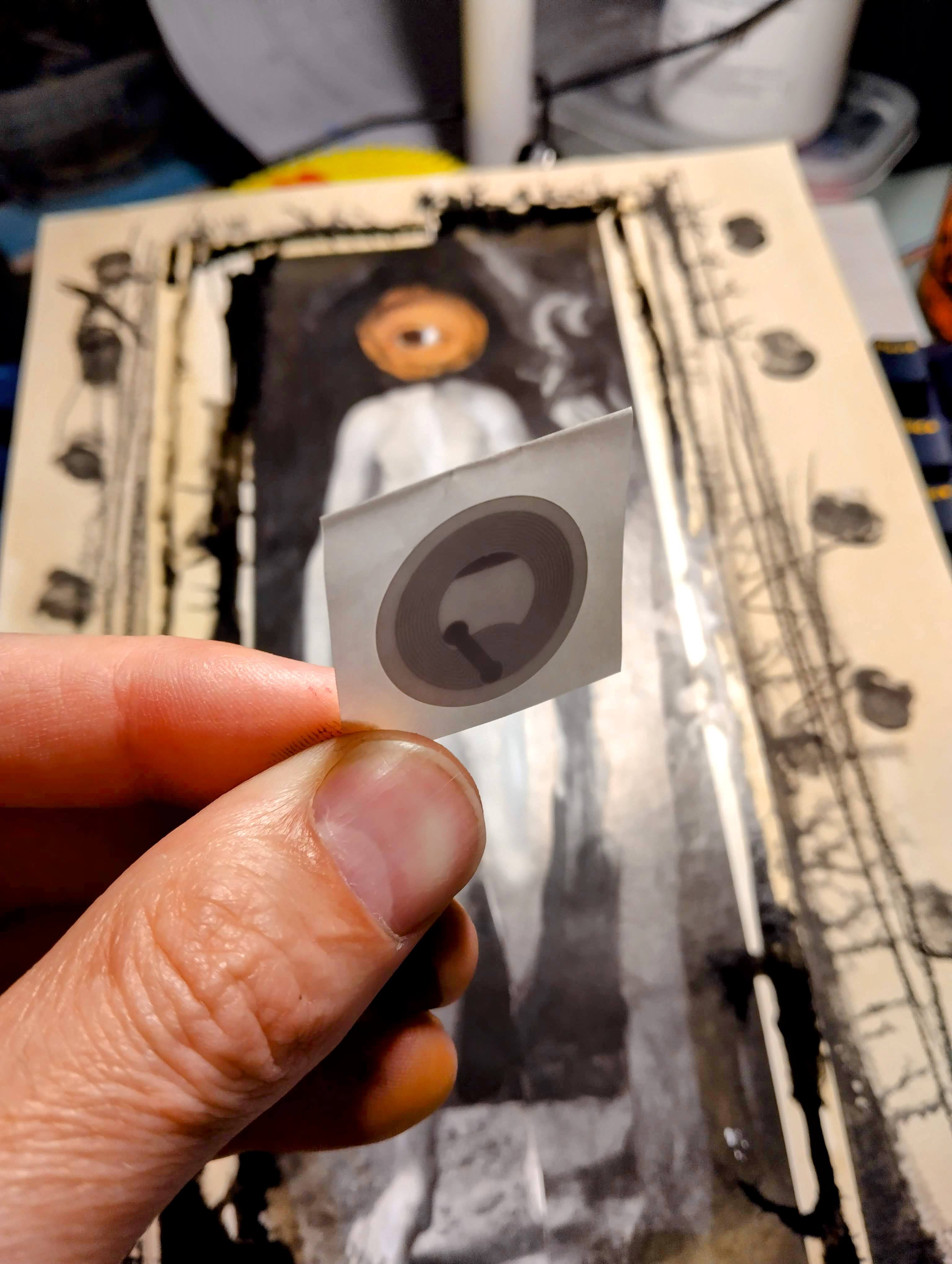
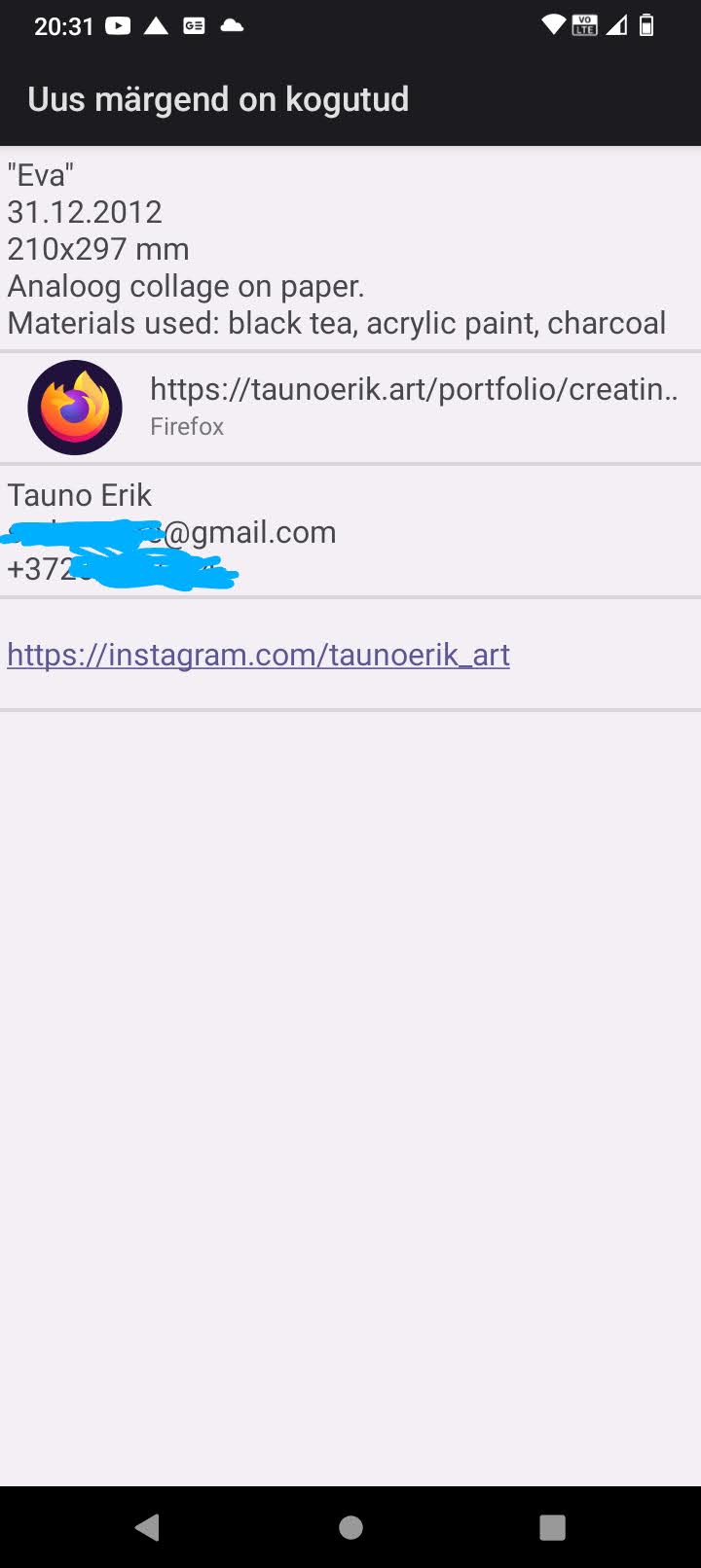
I think I found one useful way to use NFC tags. To save additional information about the artwork: materials used, thoughts, links, history etc. Or the titles of the work which I always forget. It’s like metadata on digital files. Editing can be password protected.
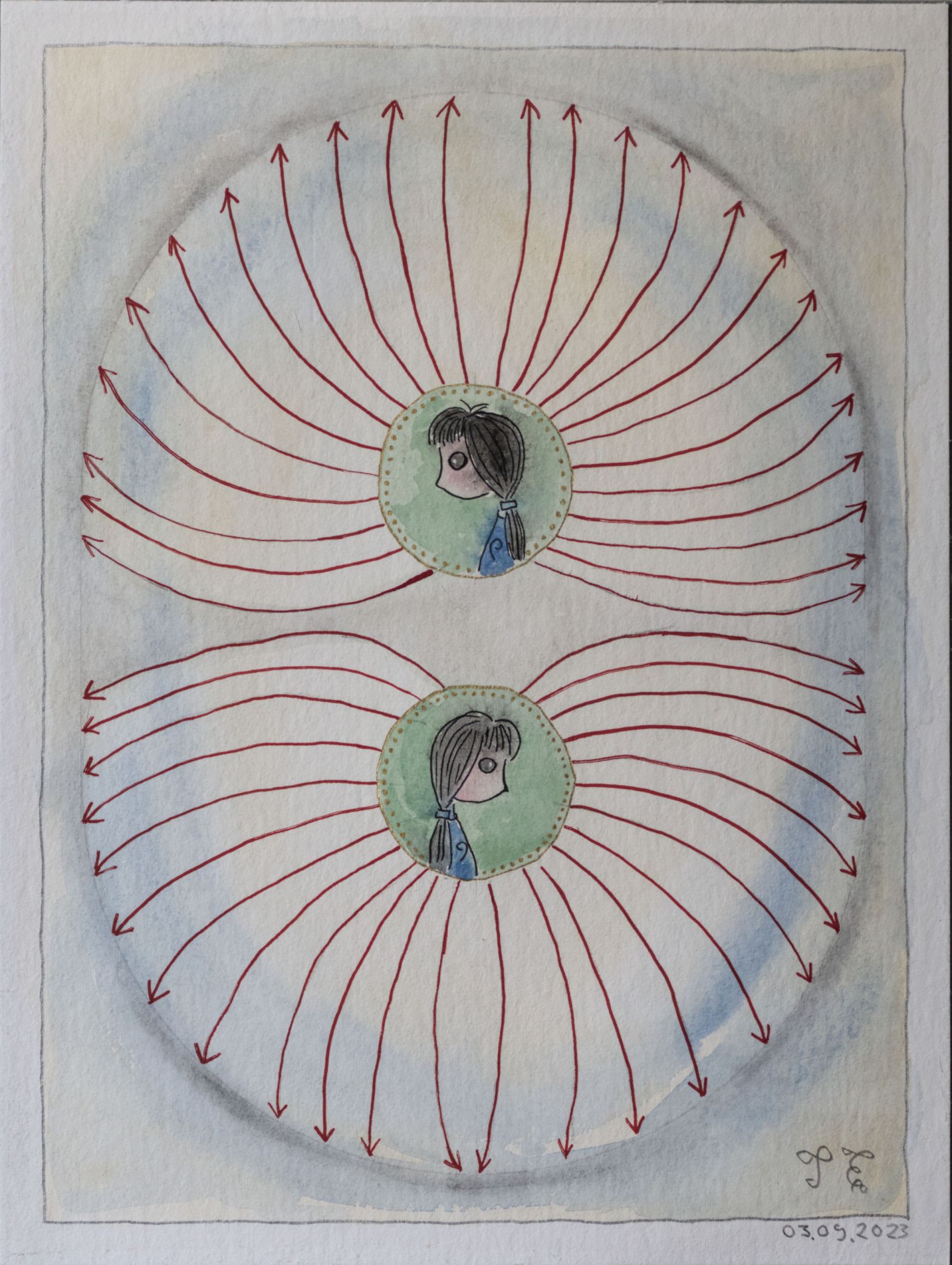
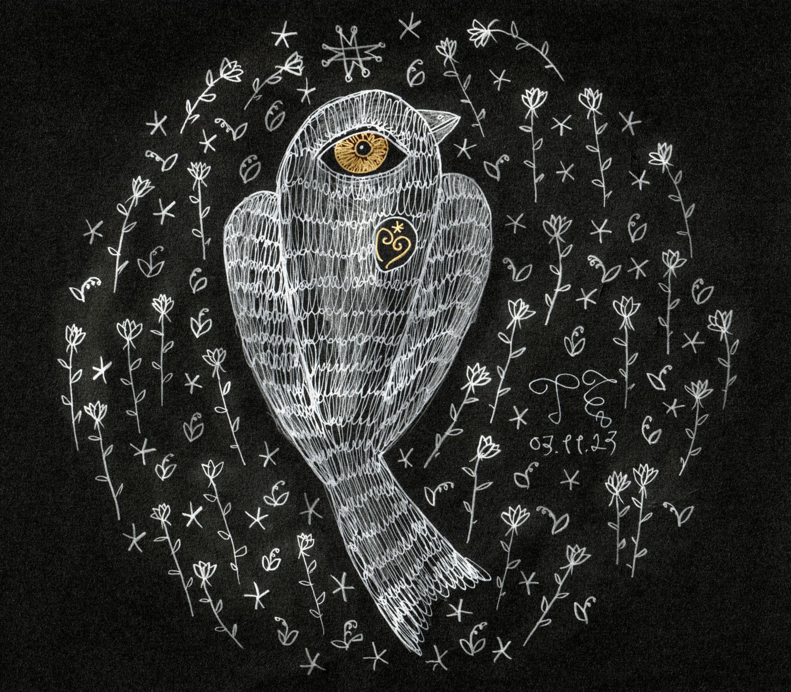
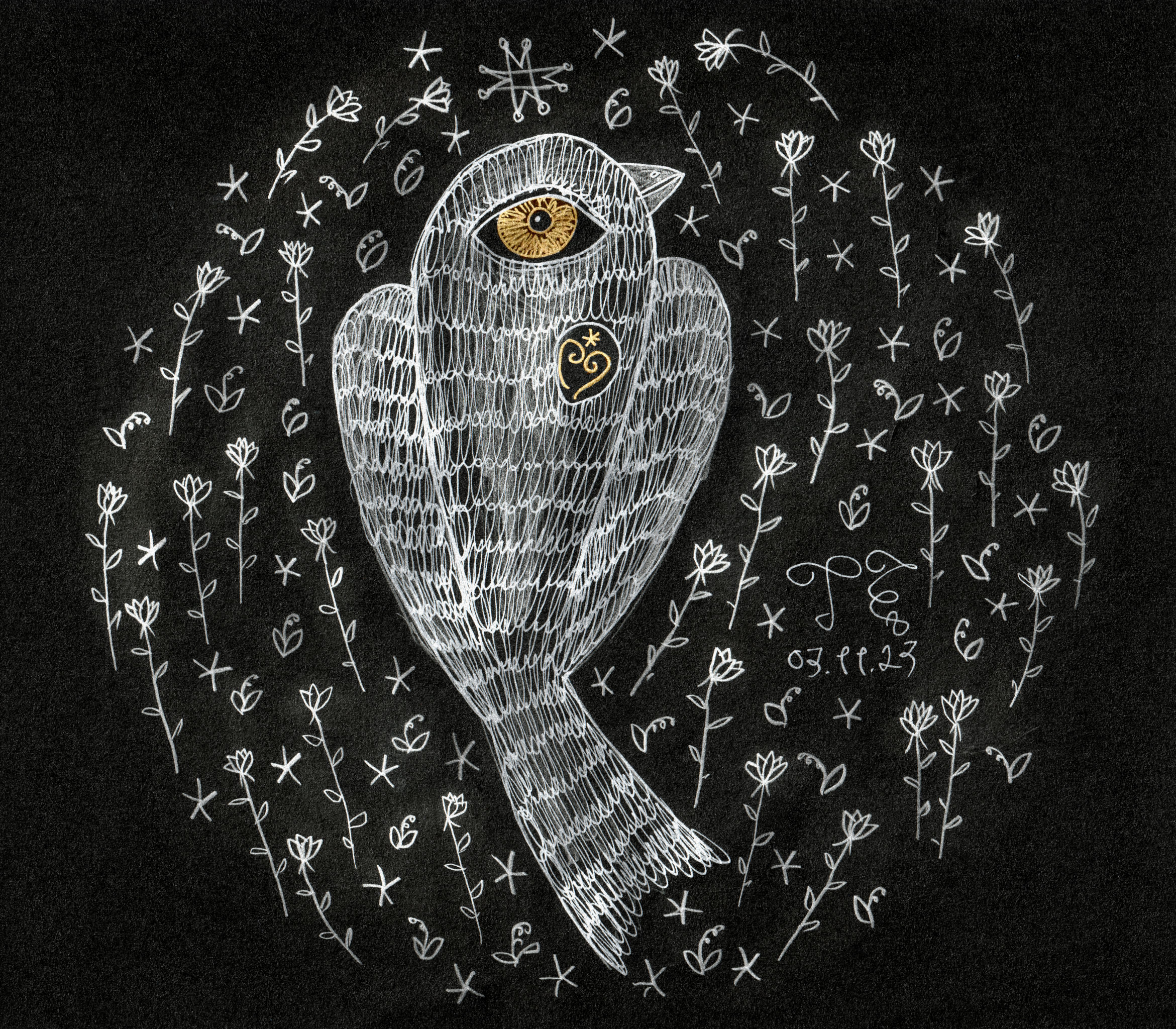
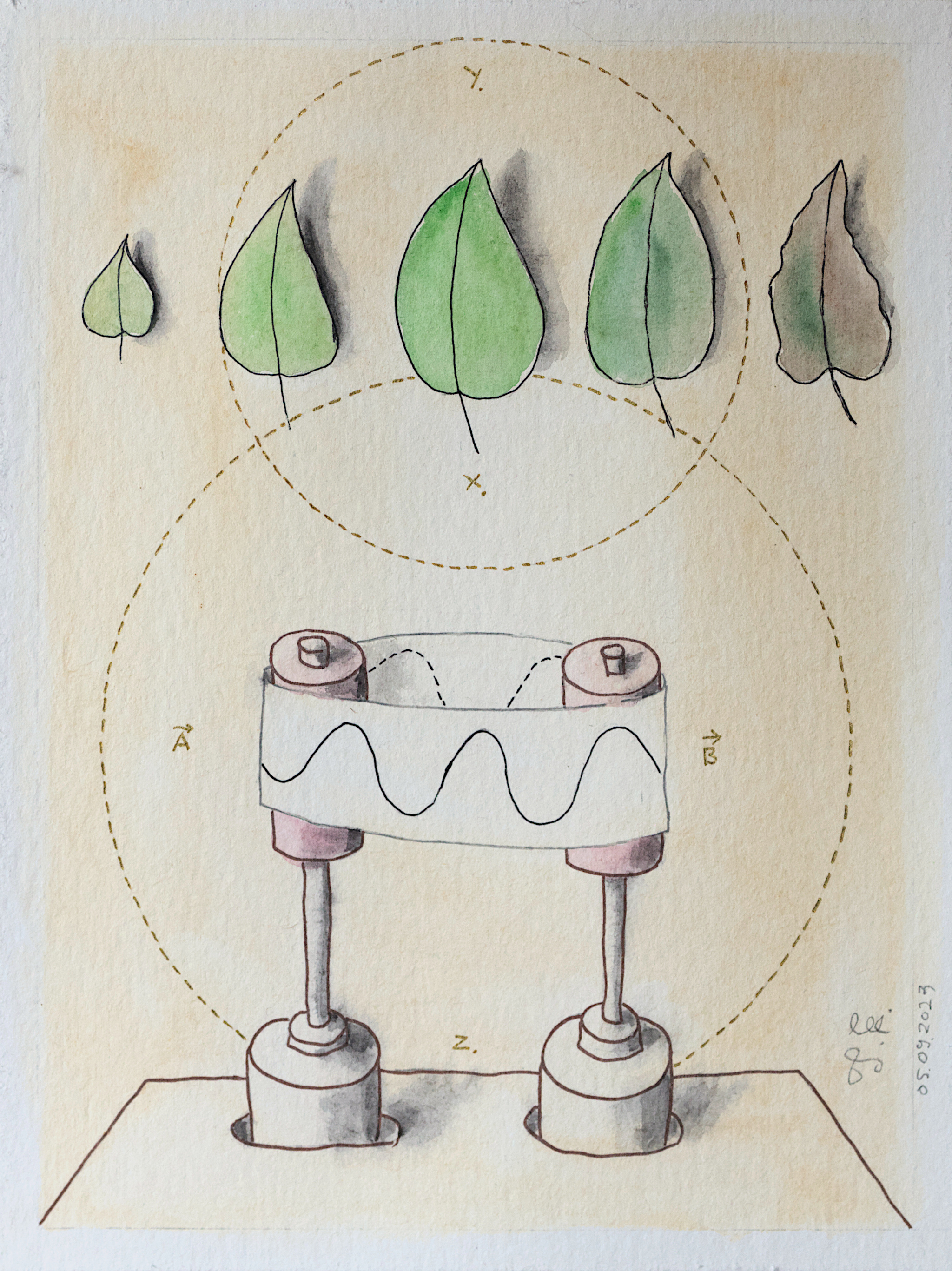
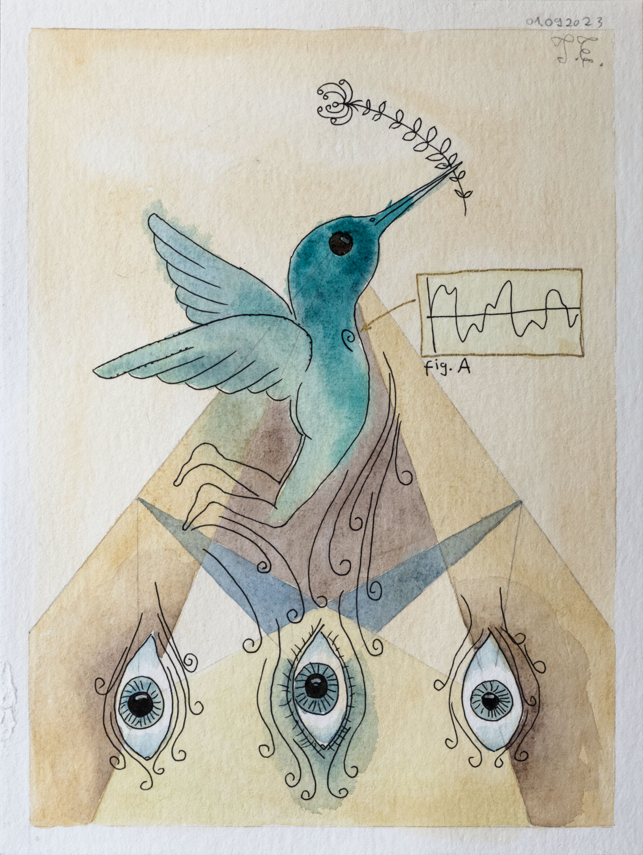
Here are two works that go Semioculus Collage Exhibition on 30.11.23 at Typa in Tartu.

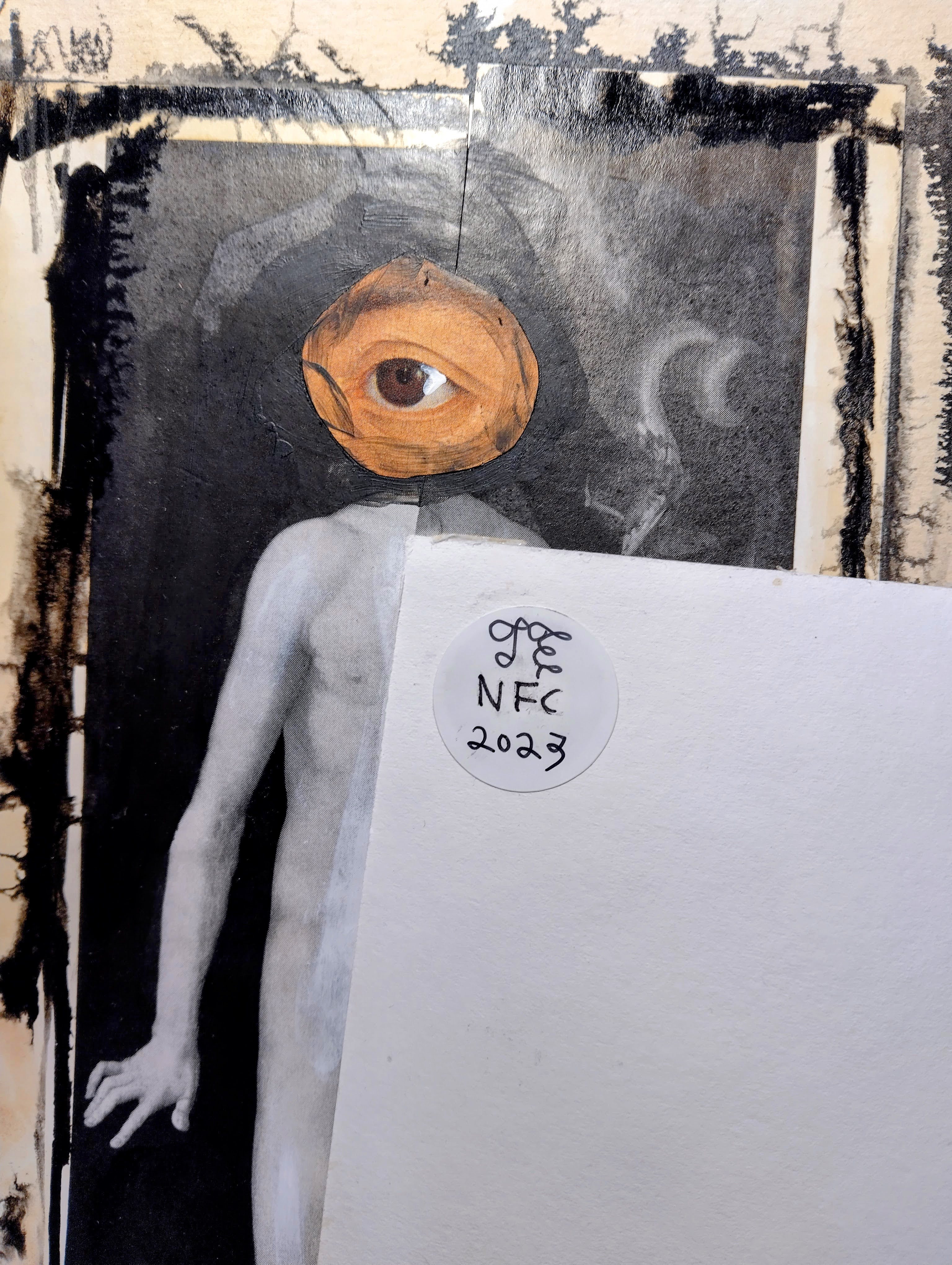

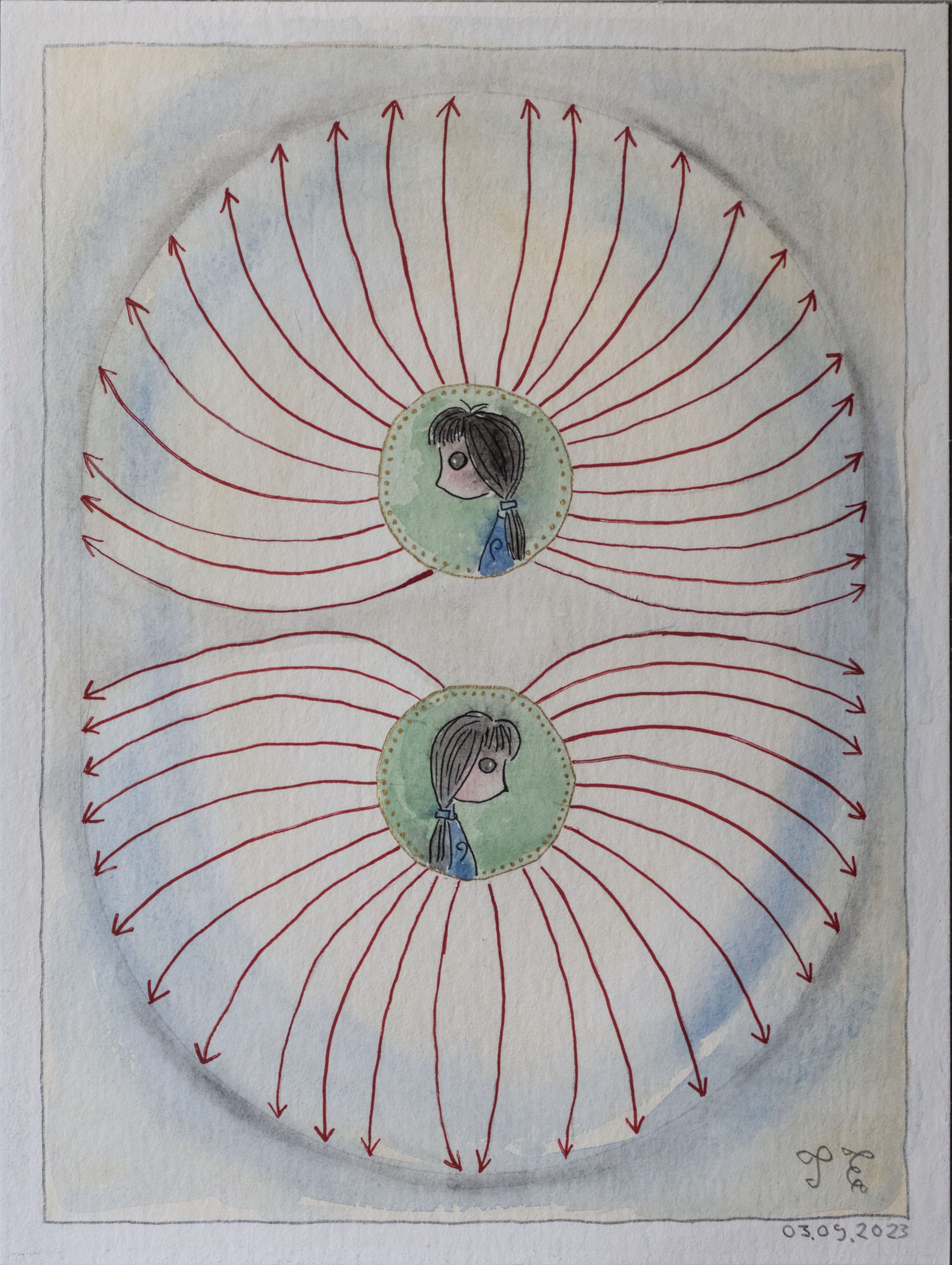

Tauno Erik, 2023, 24*32 cm


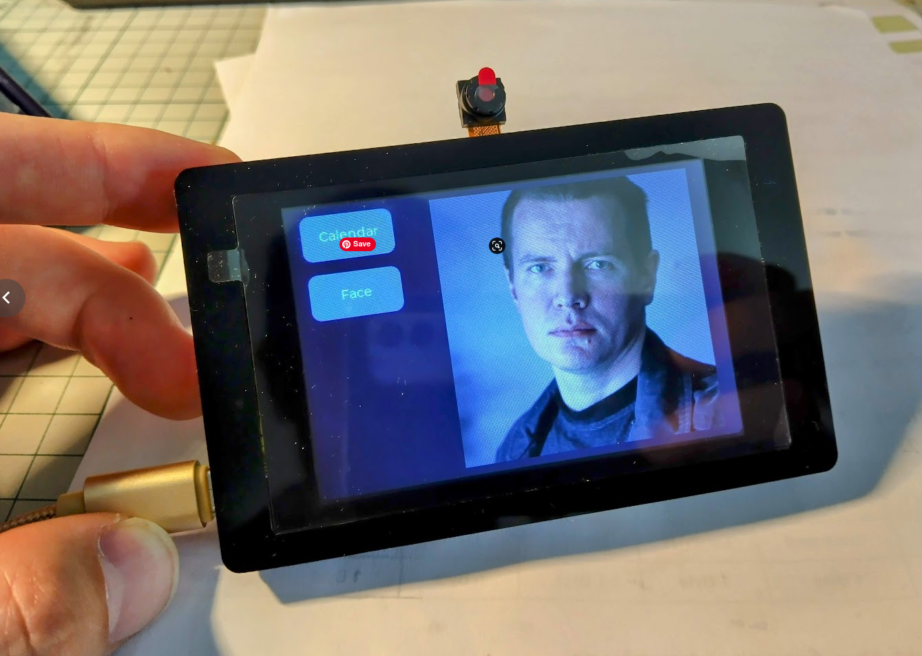
I recently got this small touch display 480×320 with a built-in ESP32-S3 module from Elecrow. I had problems programming it and it turned out that Ubuntu 22.04 does not have a CH340 driver so we have to install it manually. Steps to do this:
1 . Uninstall brltty (Unless you have vision problems and you actually need this).
sudo apt remove brltty2. Download this GitHub repository: github.com/juliagoda/CH341SER
git clone -b ubuntu https://github.com/juliagoda/CH341SER.git3. Unzip and go inside, open the terminal and run: make
make4. Load module
sudo make load5. Add permissions
sudo usermod -aG dialout $usernamesudo chmod a+rw /dev/ttyUSB06. Verify
ls -la /dev/ttyUSB0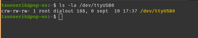
7. If you Upload, hold down the Boot button (behind the screen). And press the Reset button once.