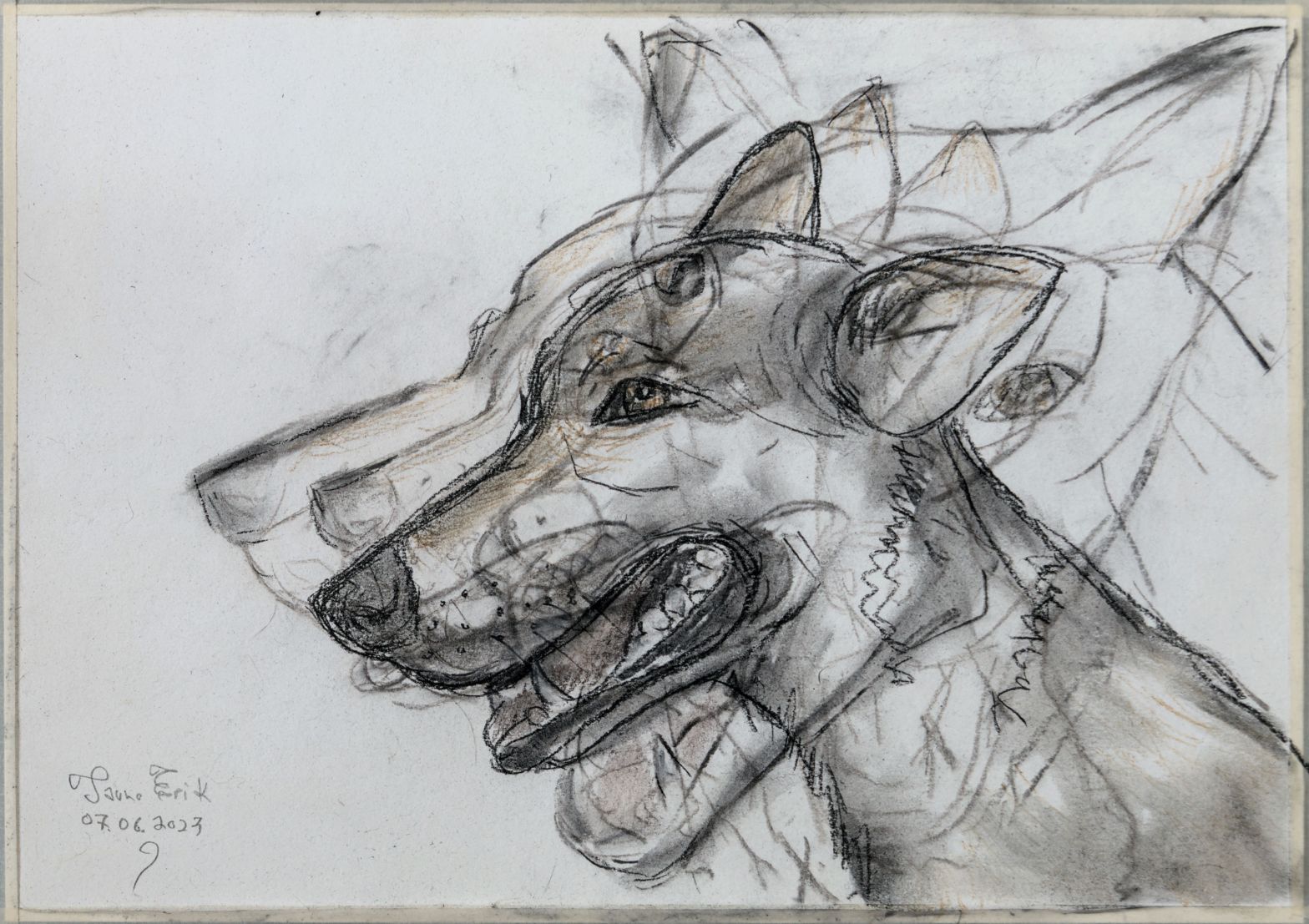
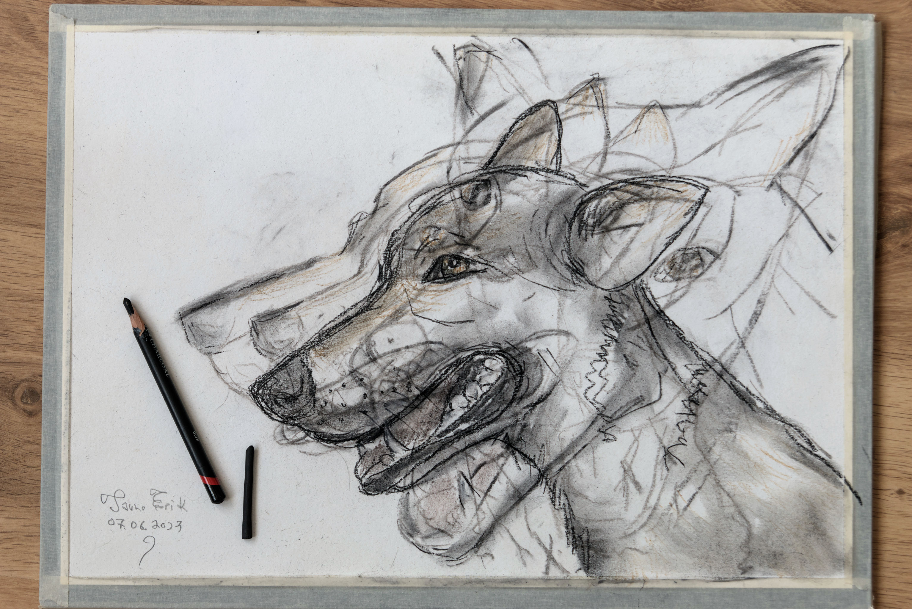
Charcoal on paper 420×297 mm. And hairspray as fixative.
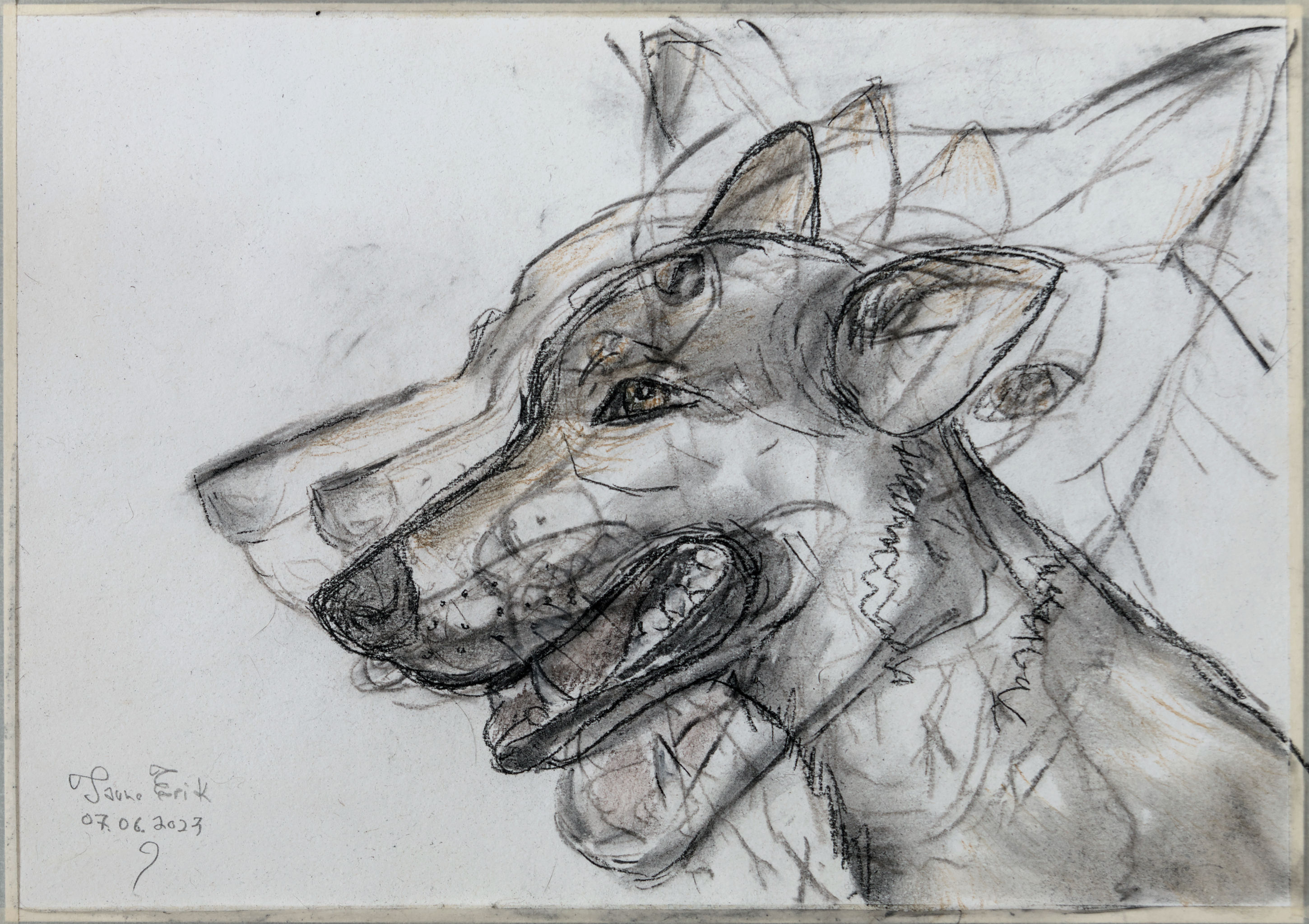
Charcoal on paper 420×297 mm. And hairspray as fixative.
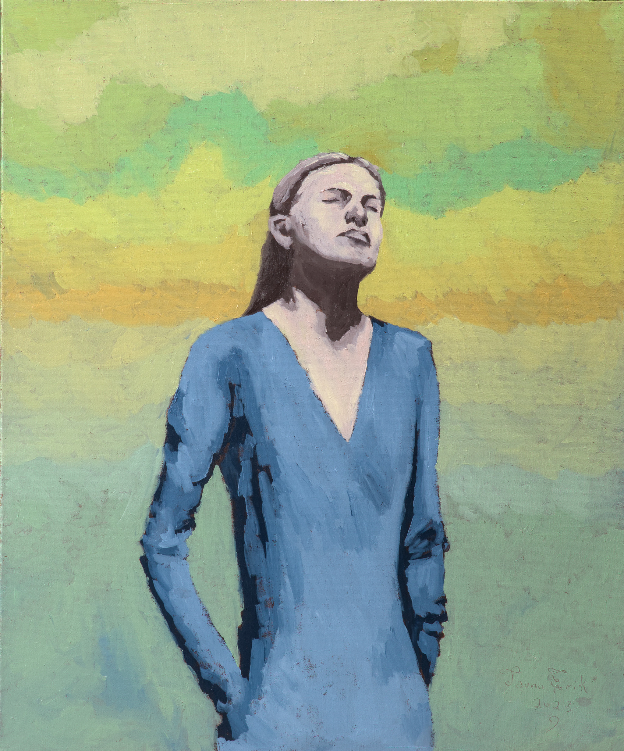
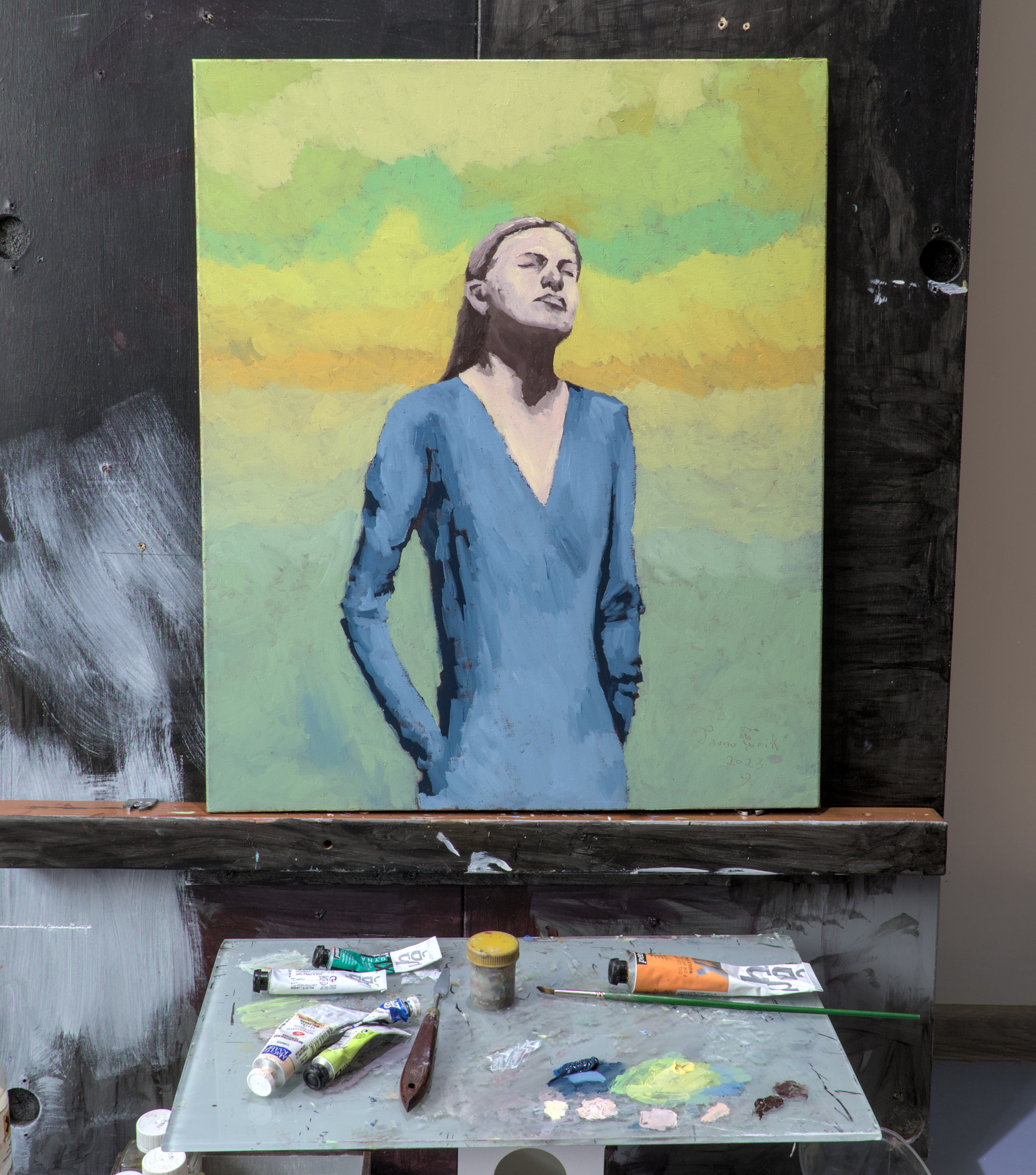
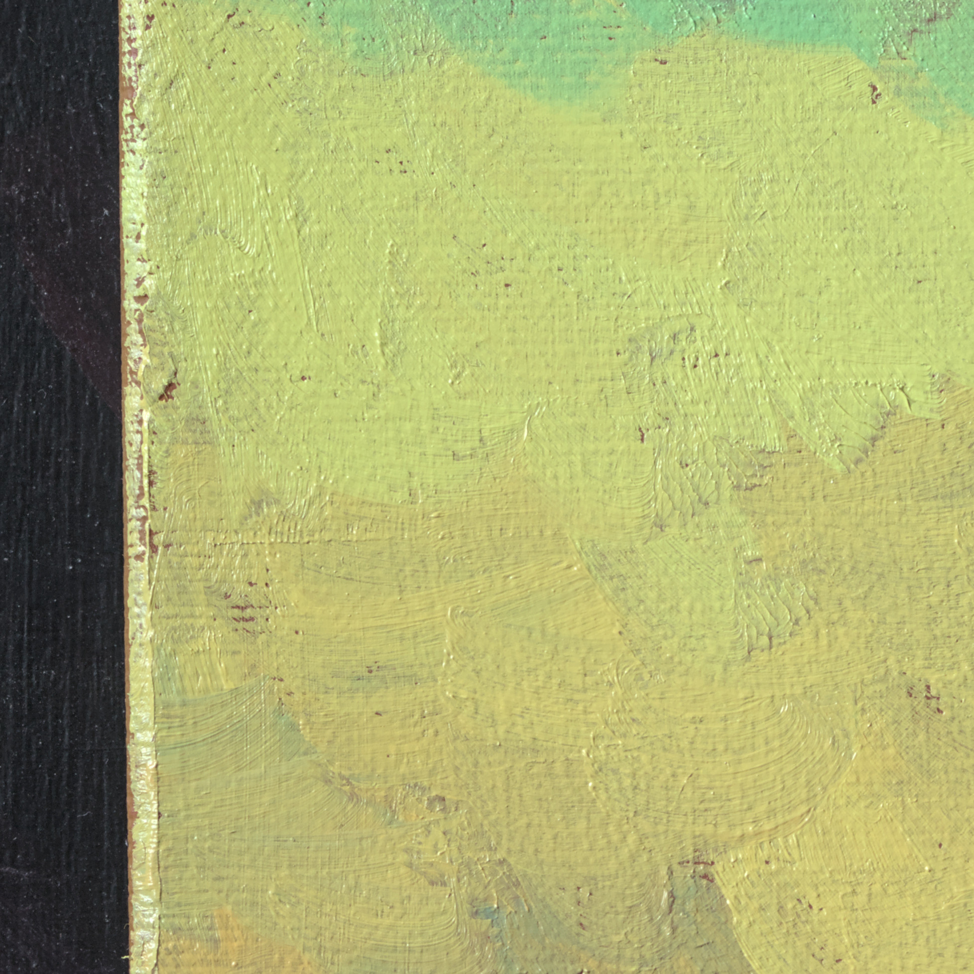
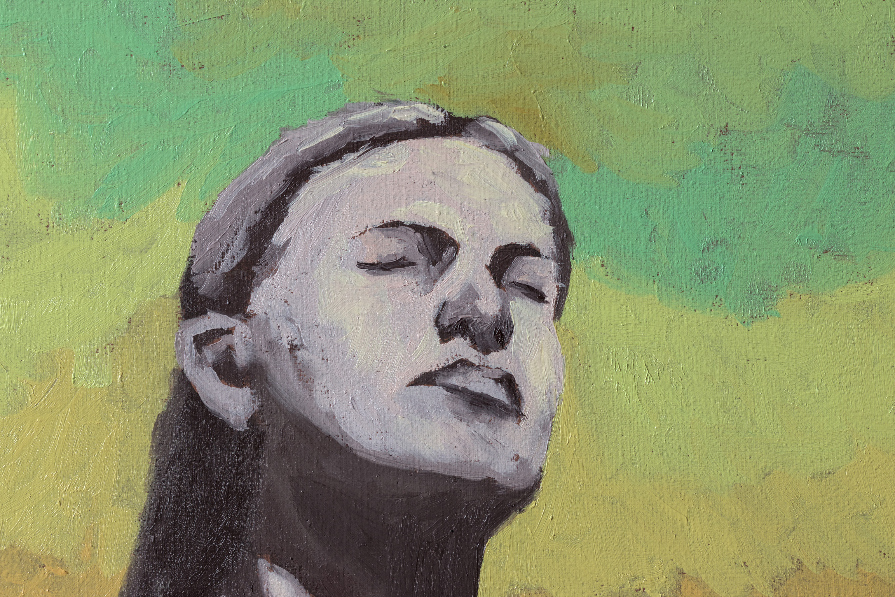
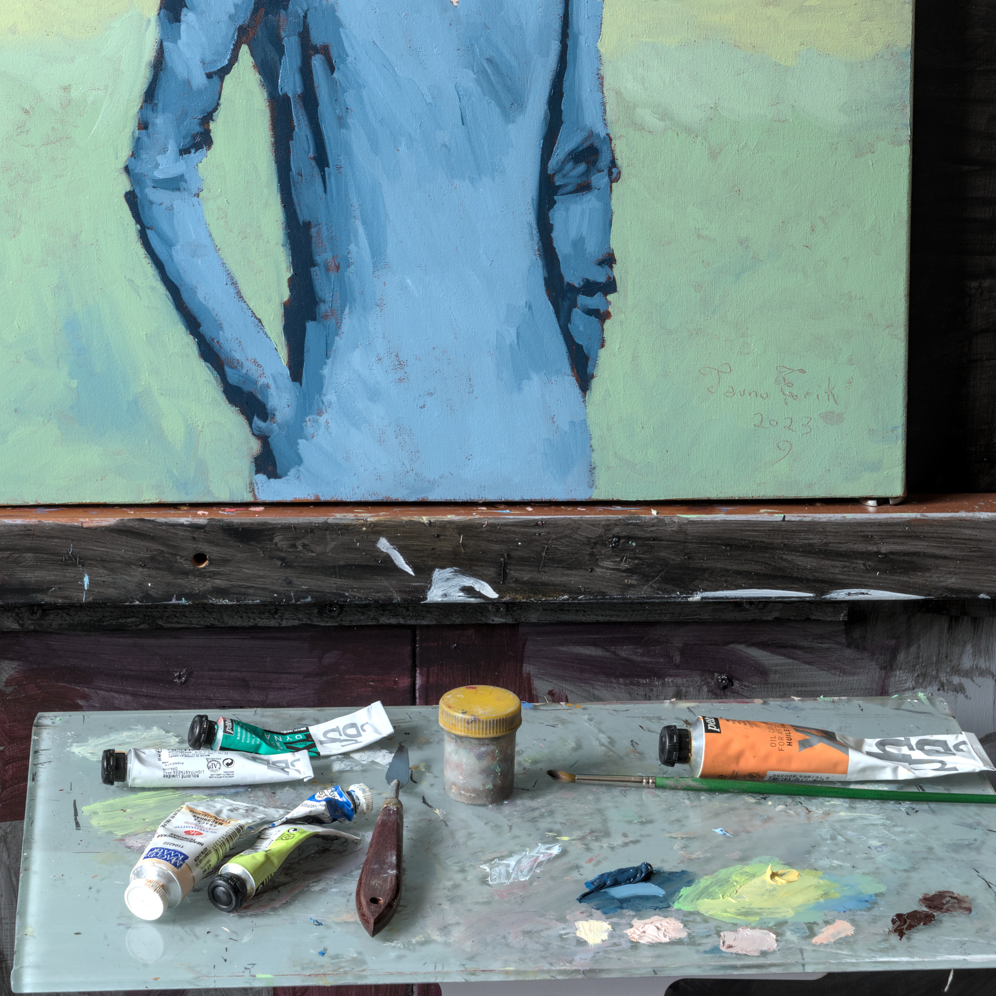
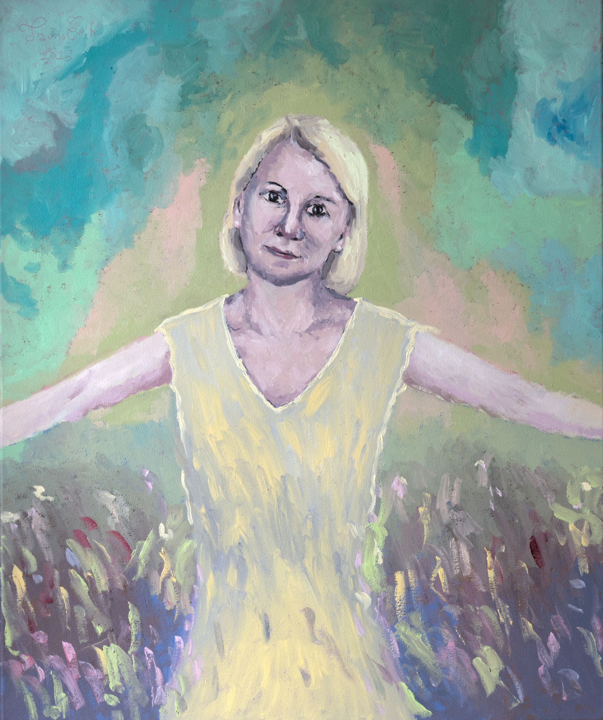
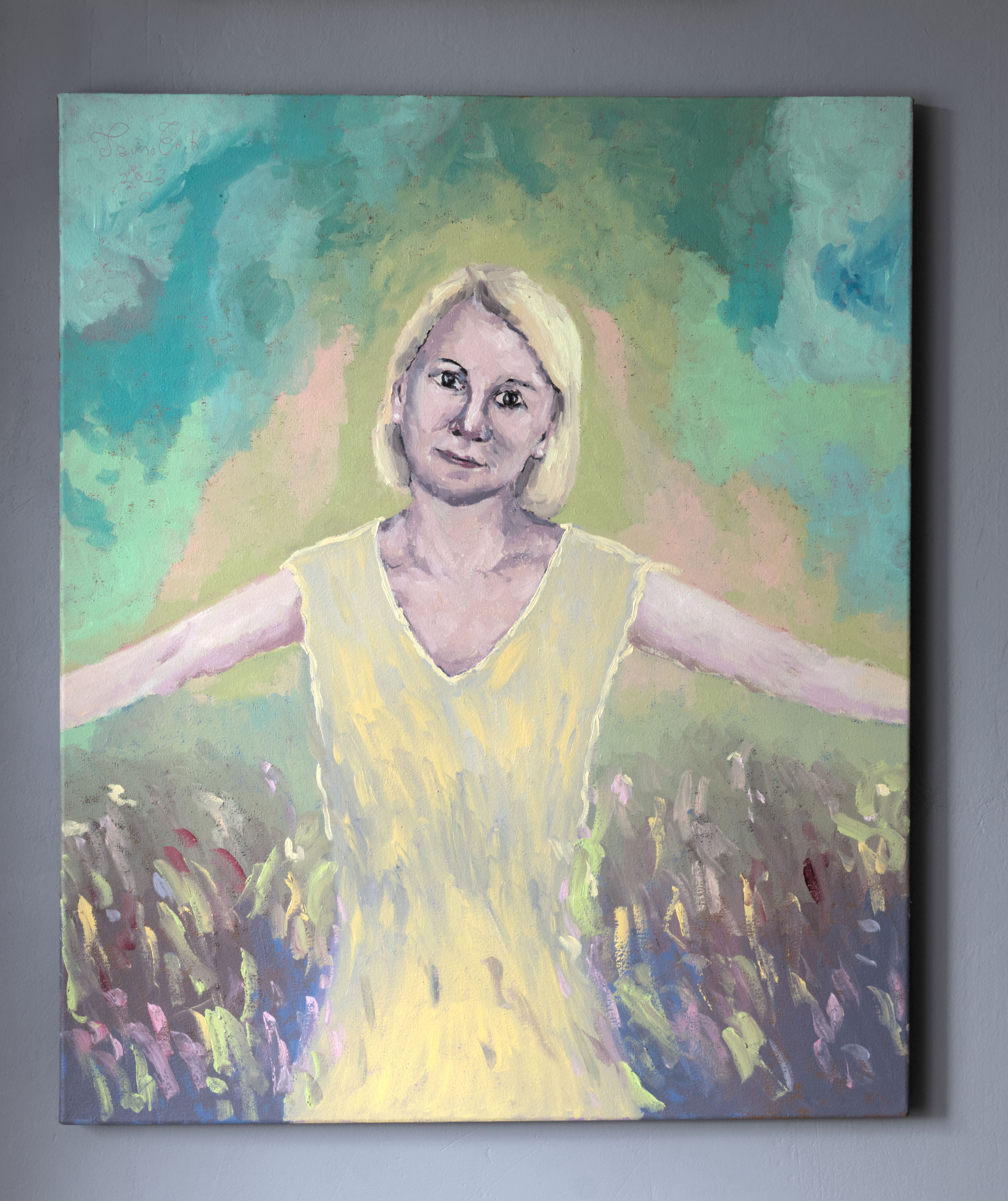
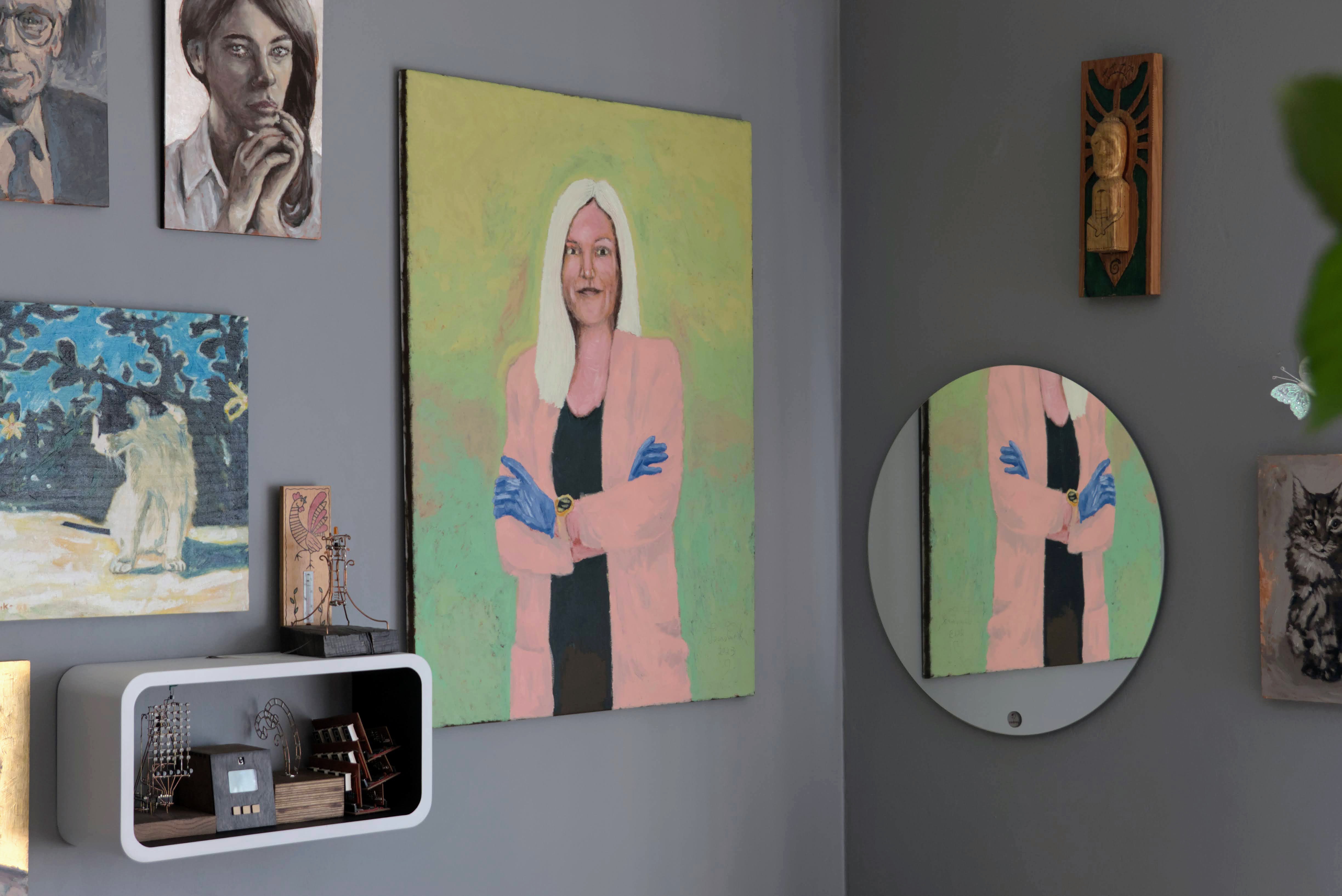
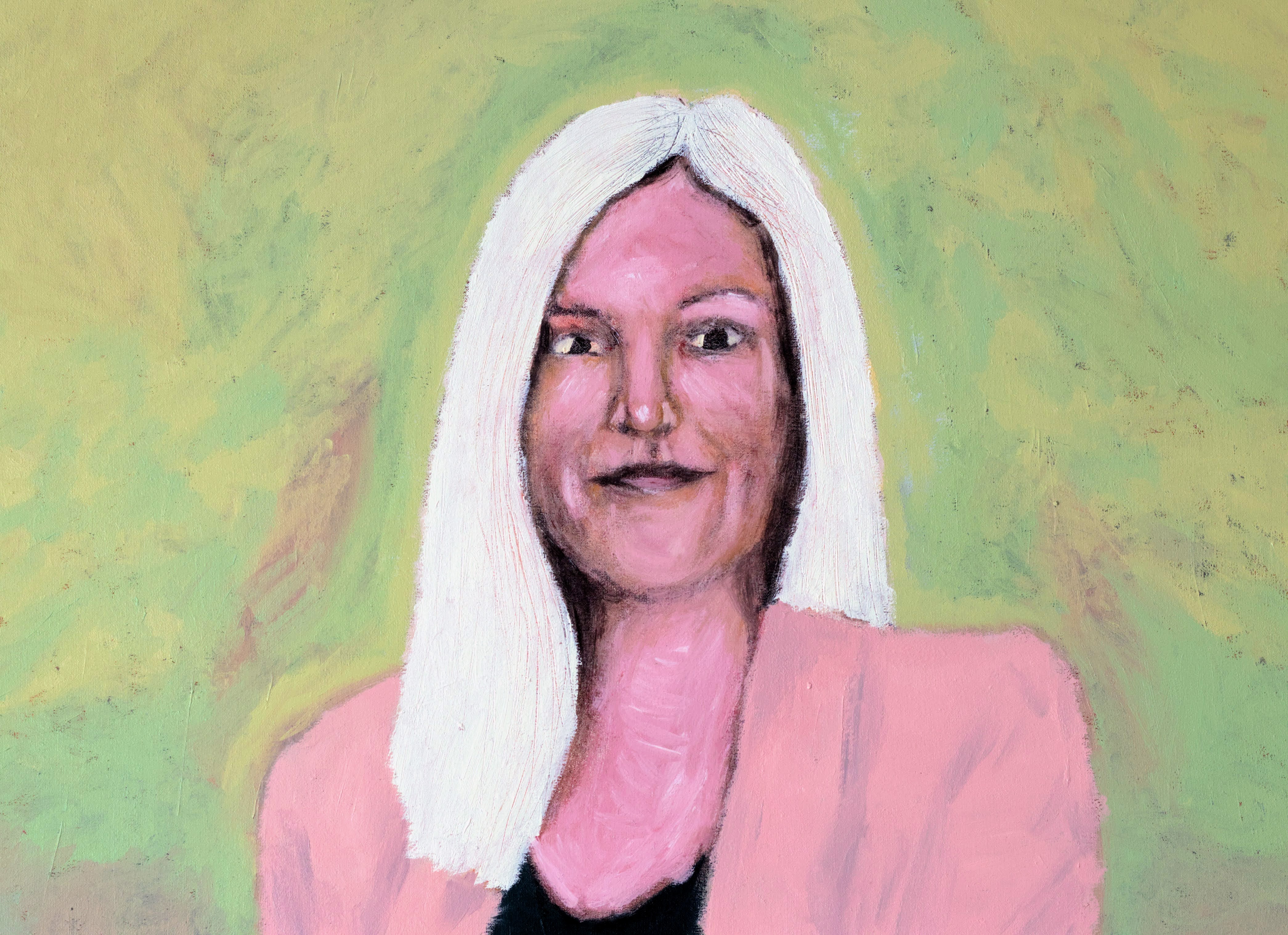
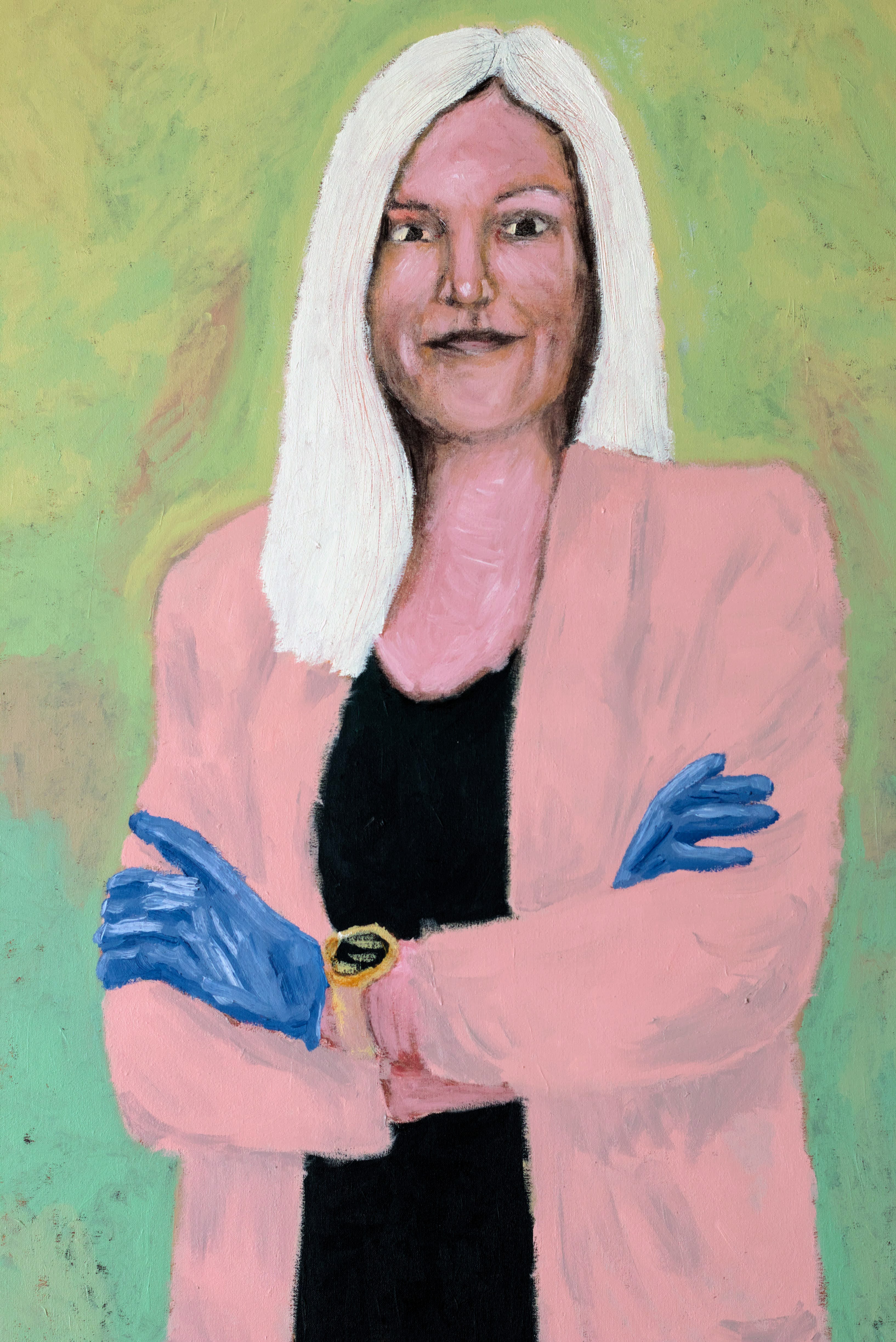
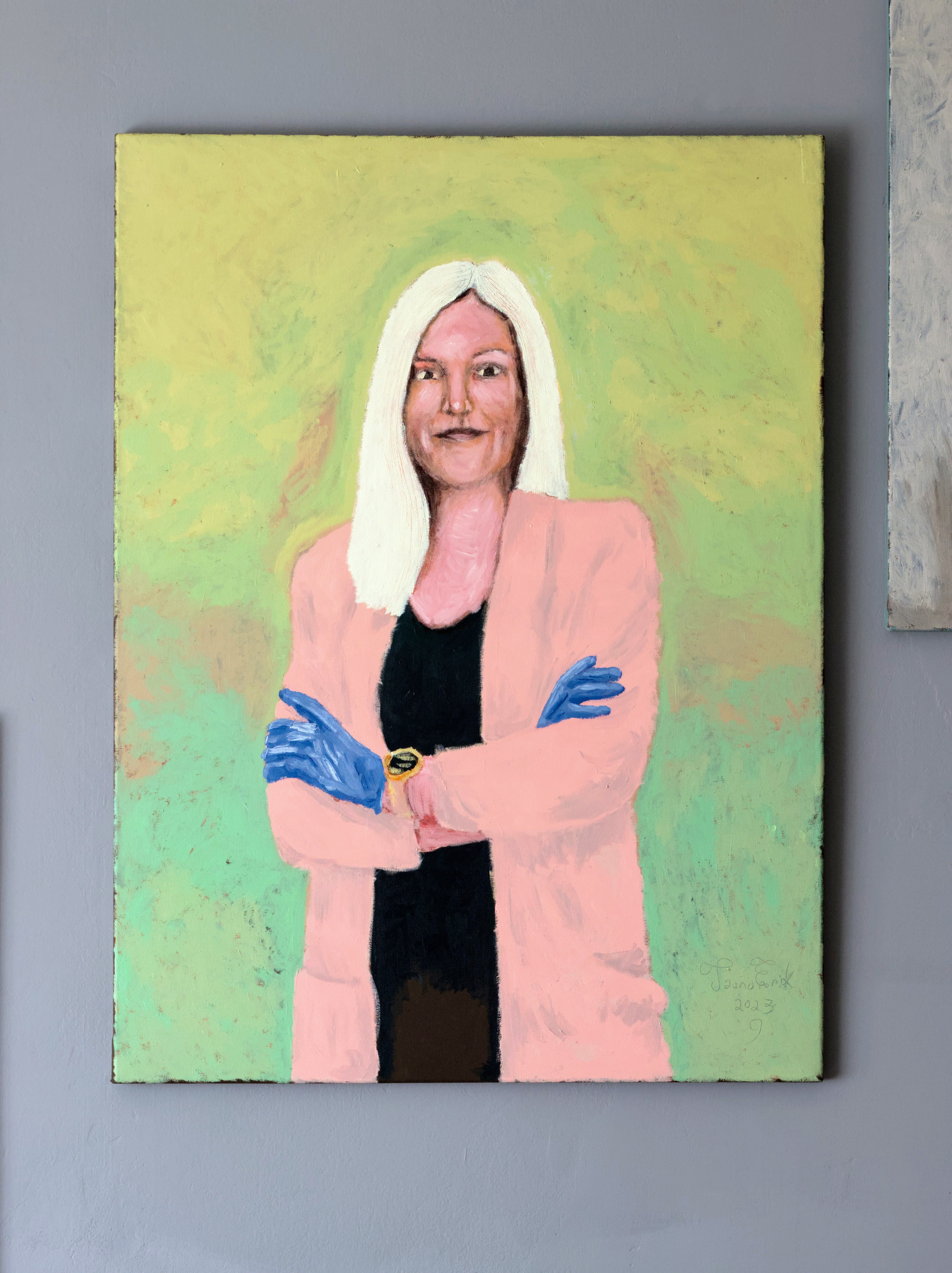
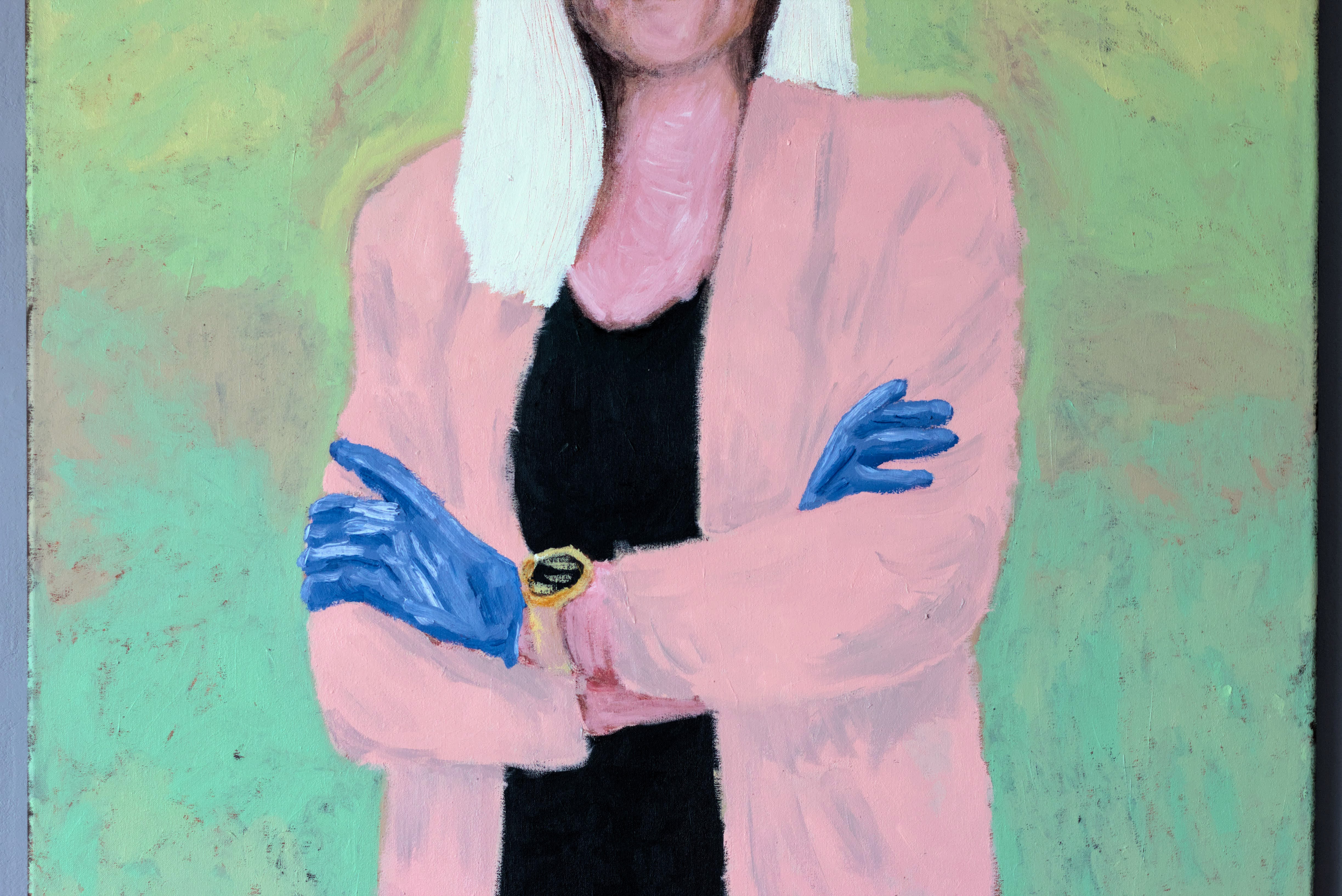
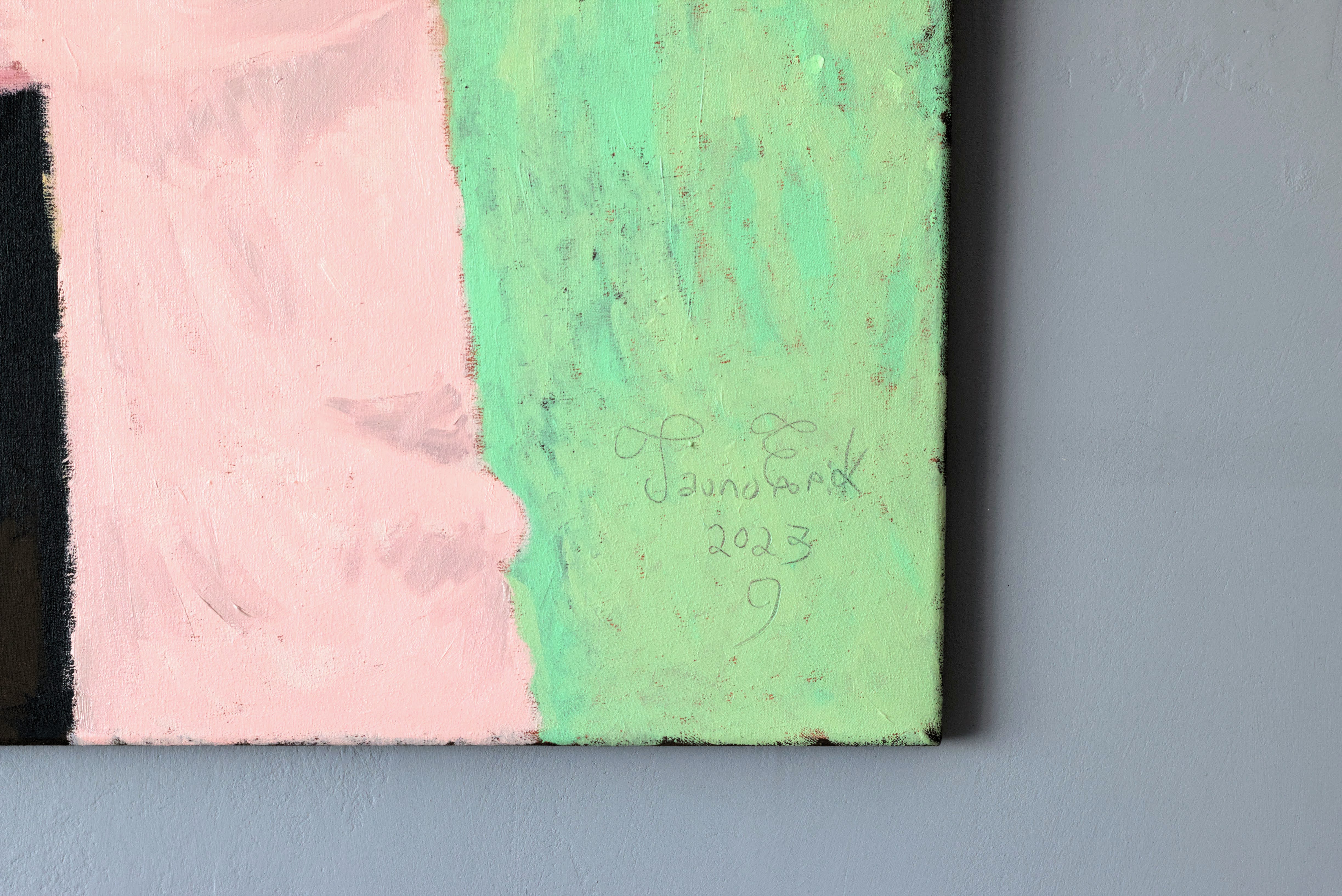
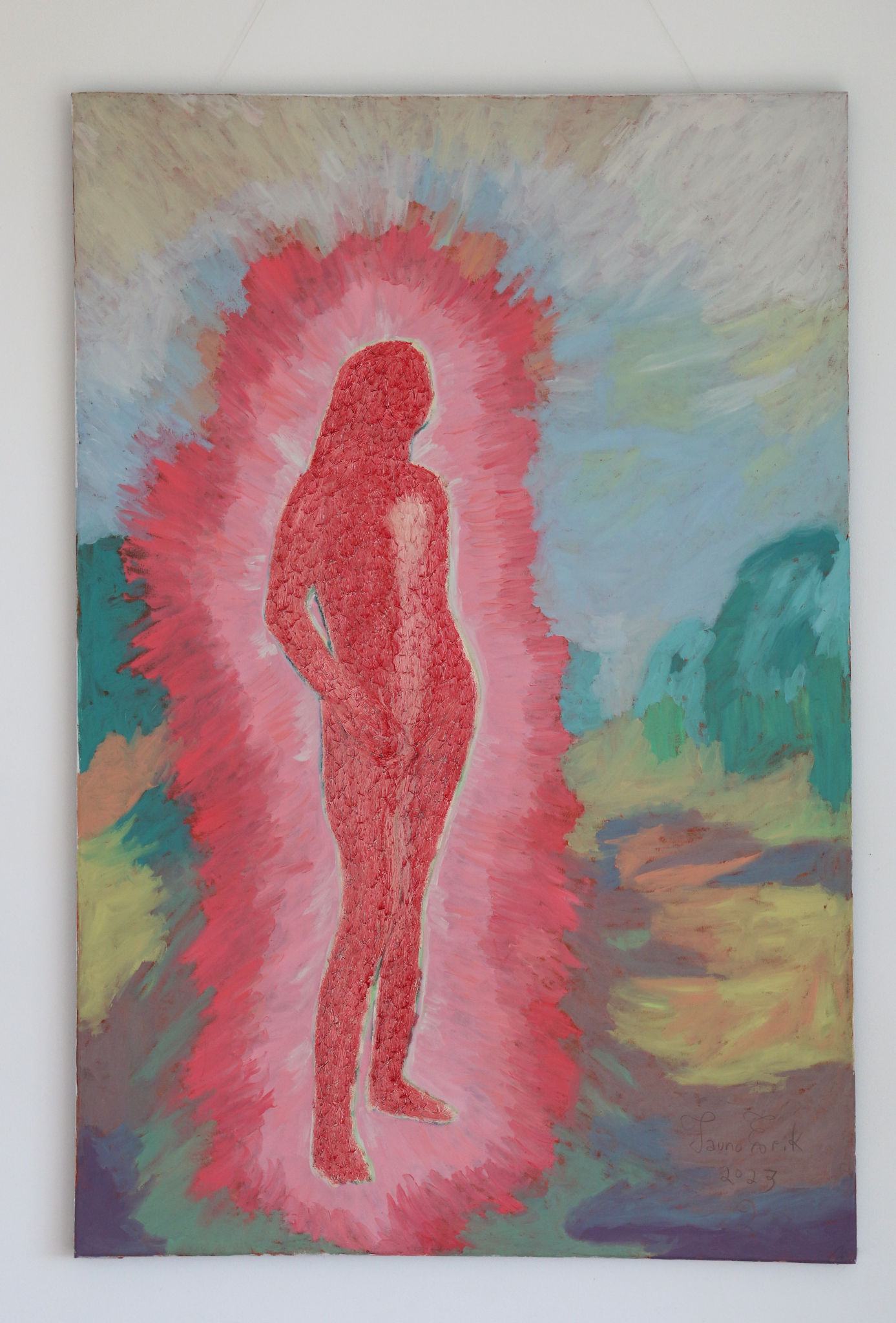
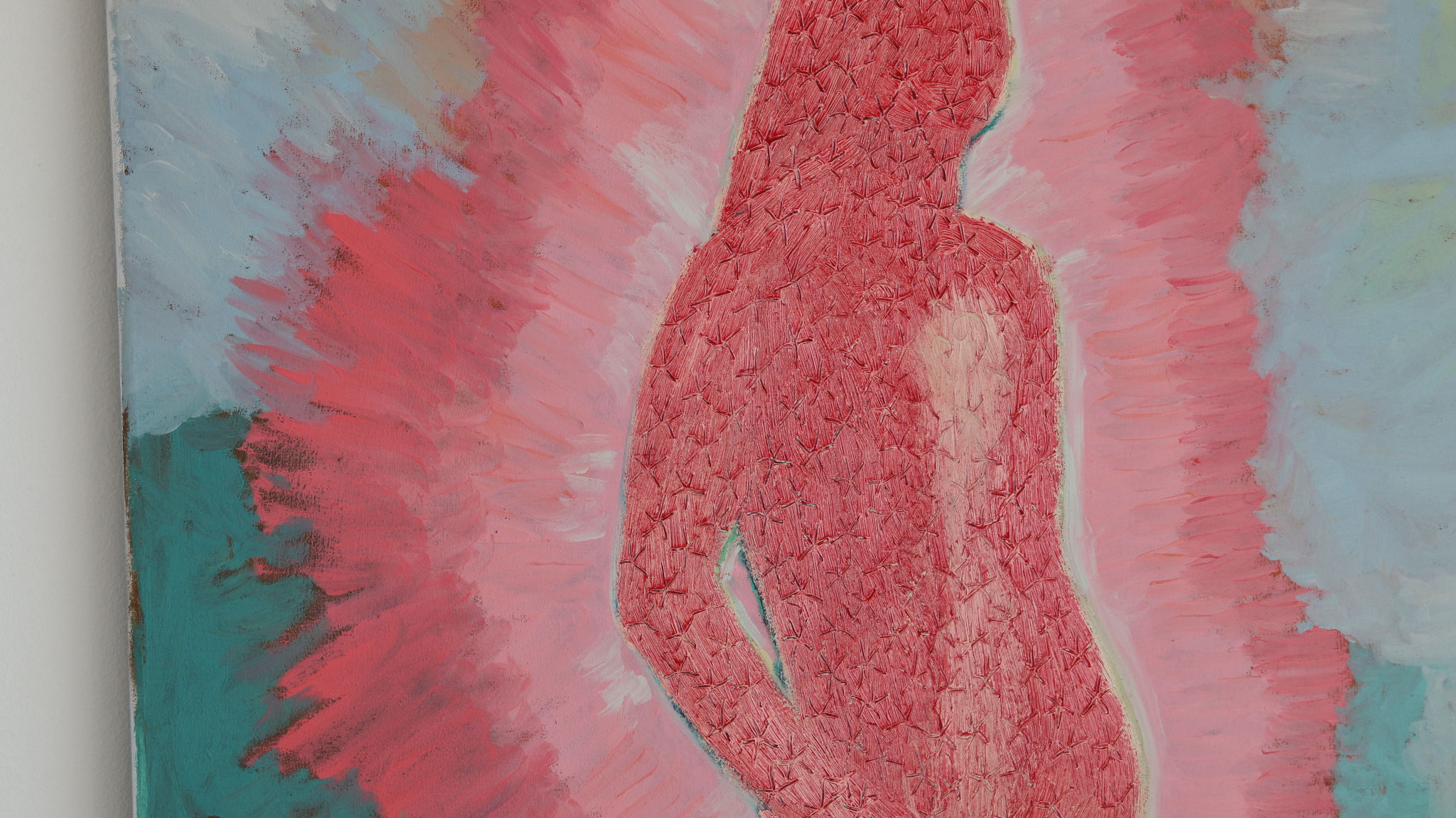
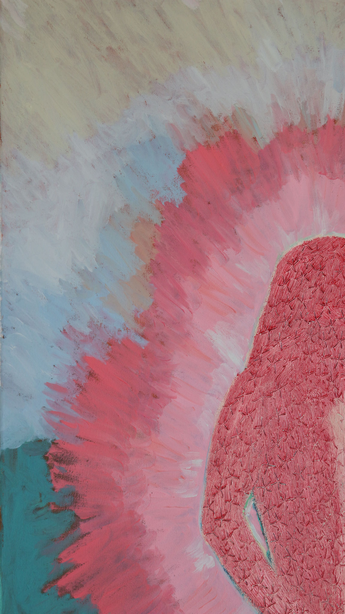
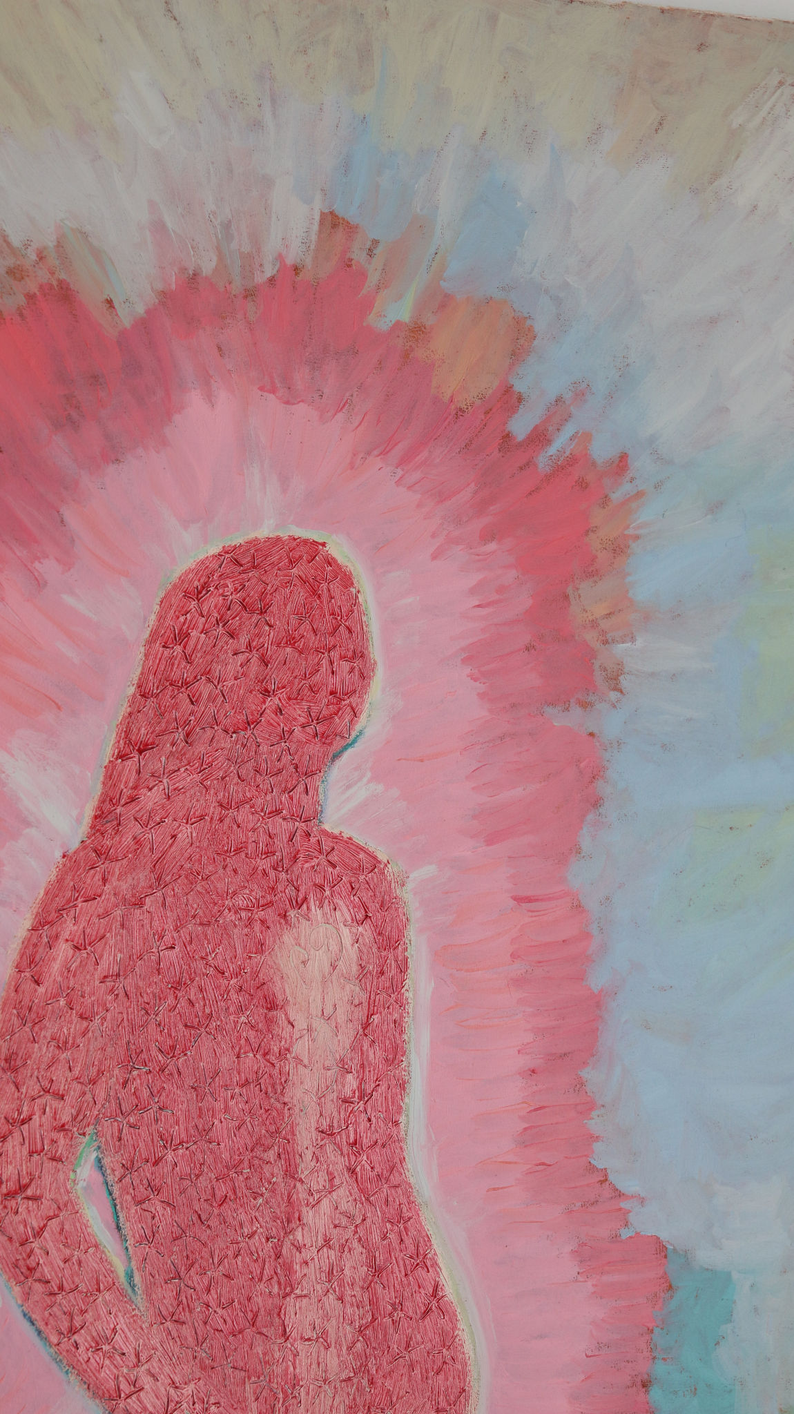
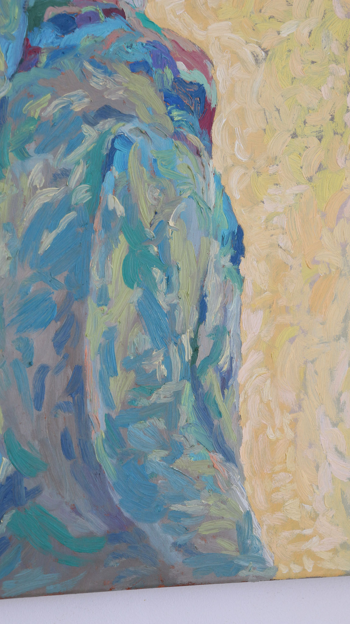
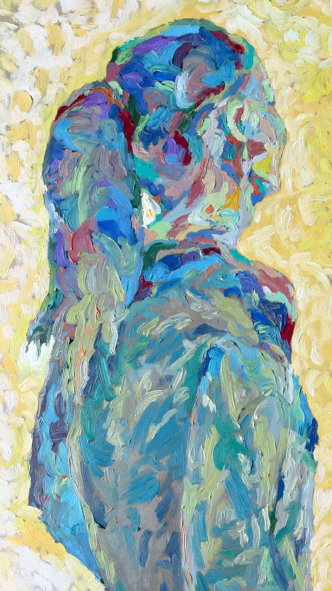
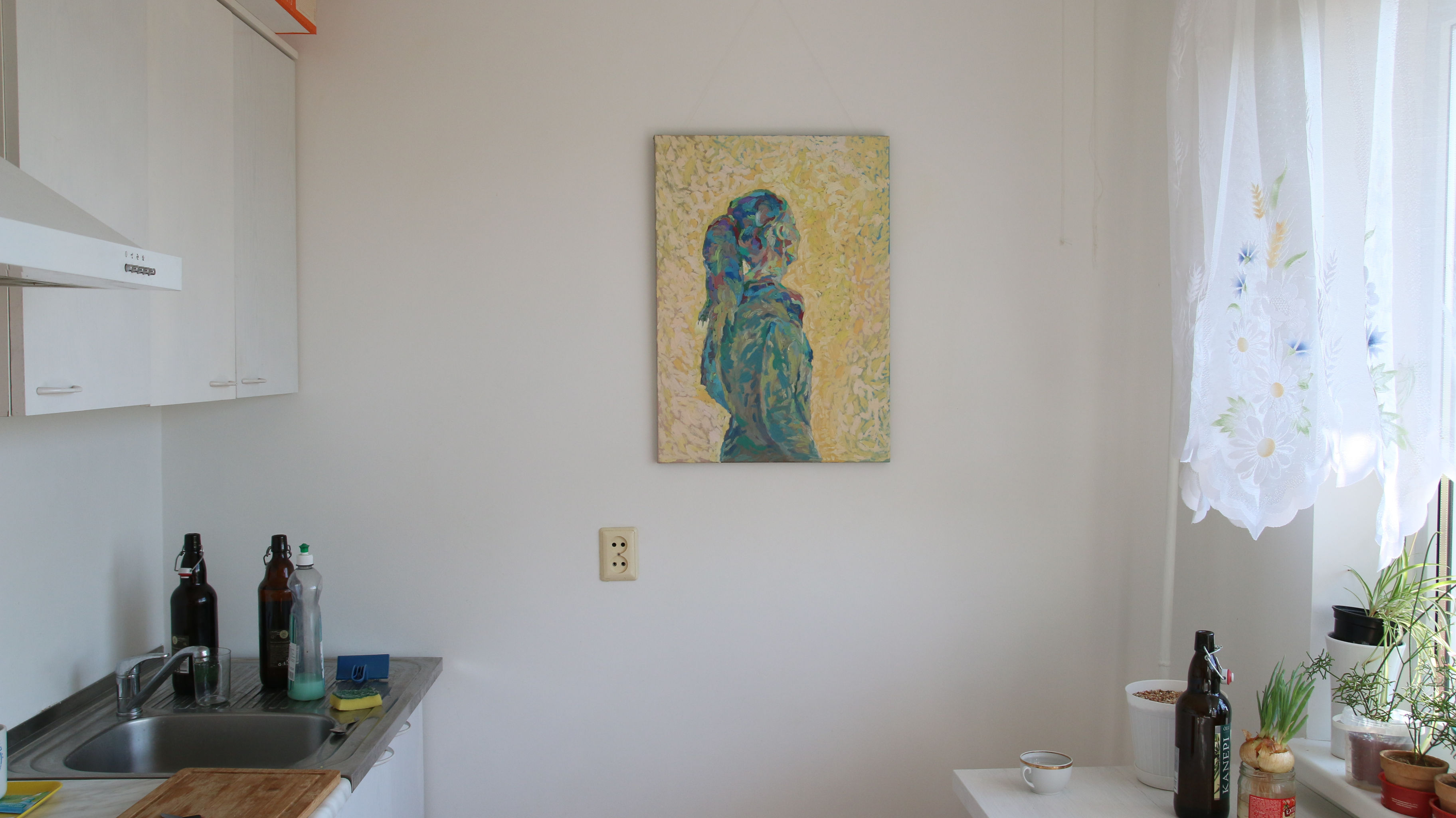
Oil painting on canvas, 50×60 cm.
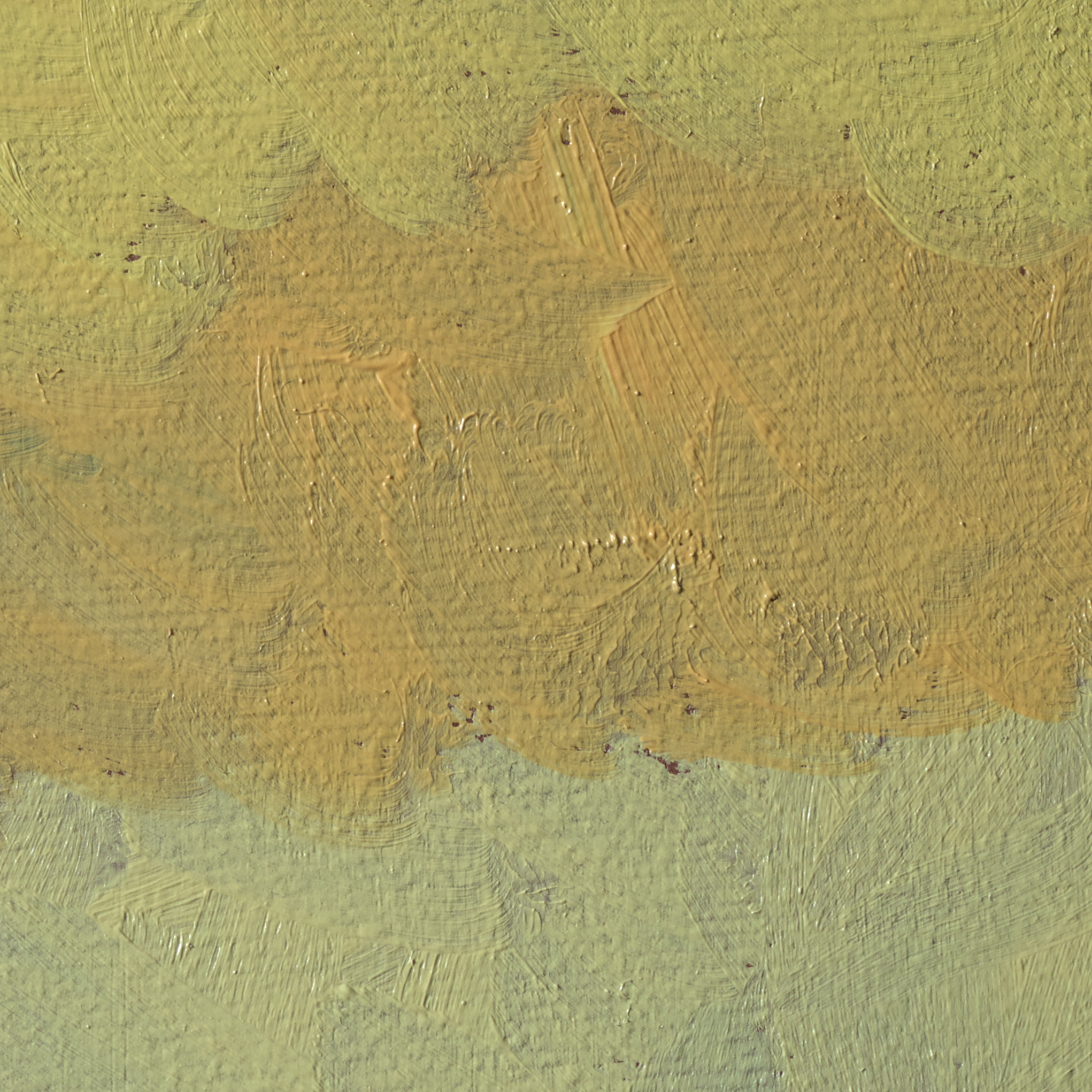
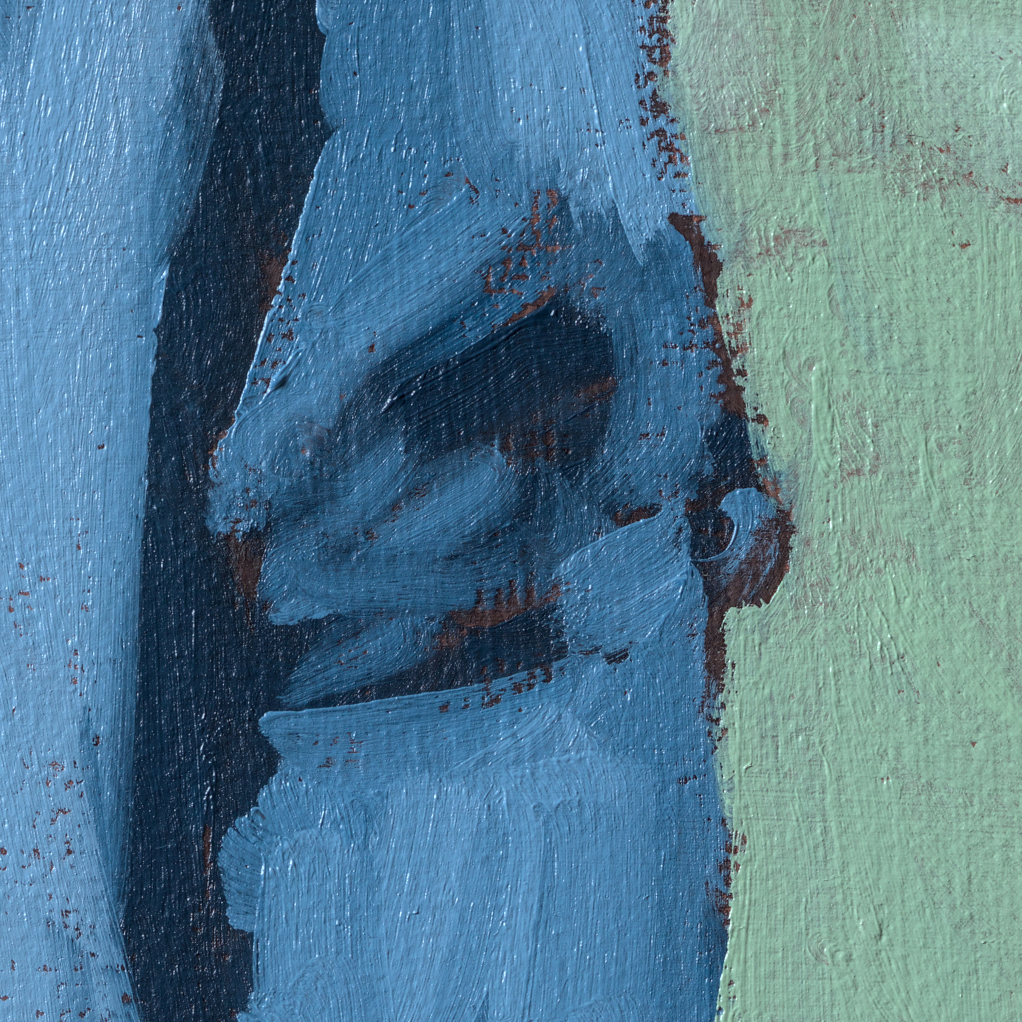
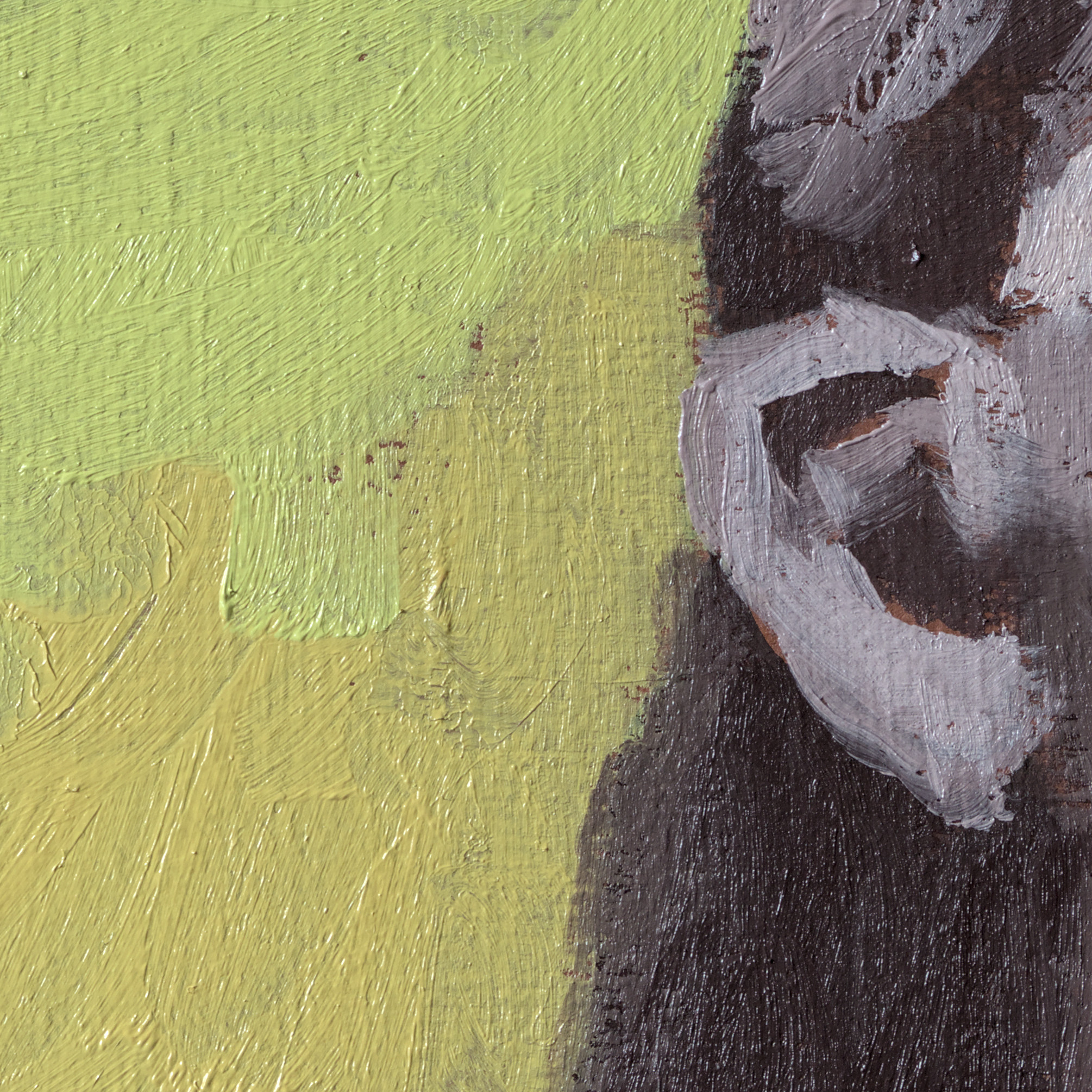
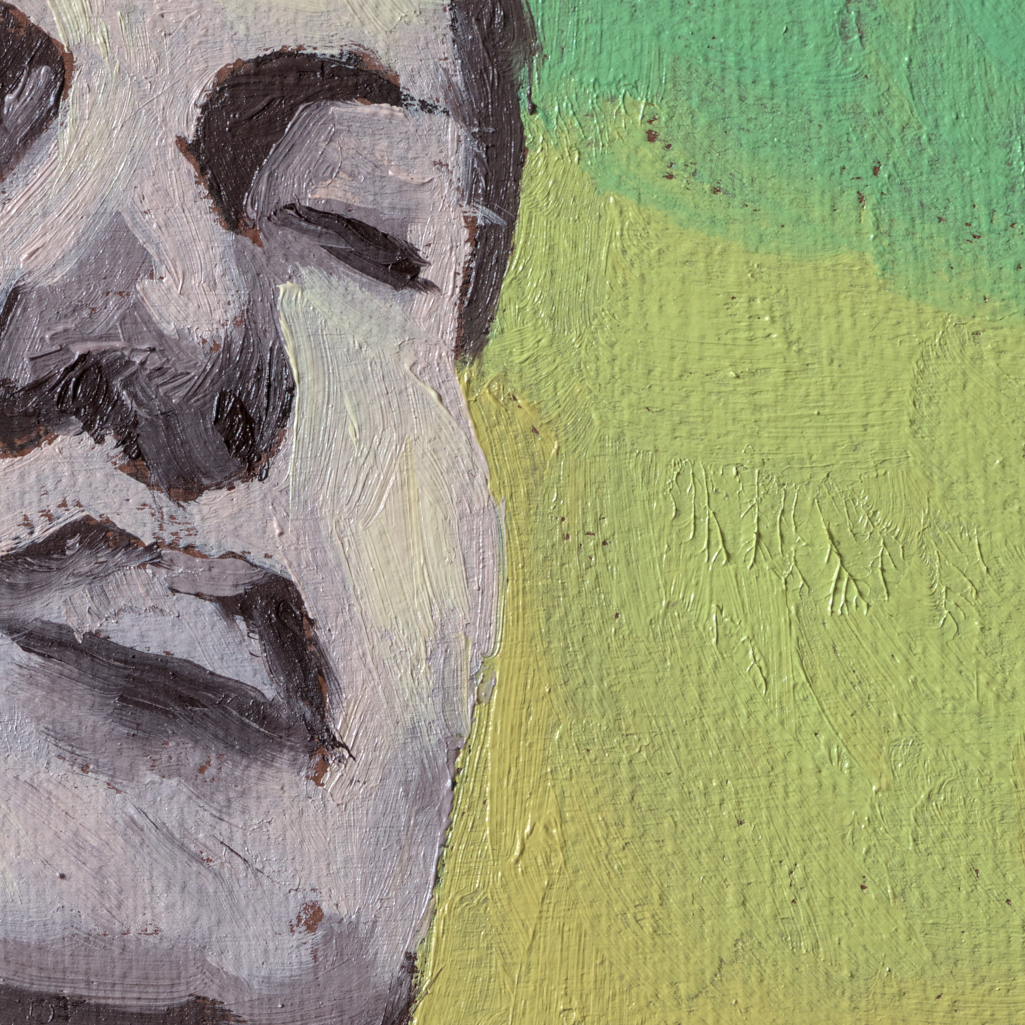
Oli on canvas, 50×60 cm.

$ curl --proto '=https' --tlsv1.2 https://sh.rustup.rs -sSf | shLaeb alla Rusti paigaldamise skripti ja installib tööriista nimega rustup. Mis paigaldab kõik vajalikud asjad ja hoolitseb uuenduste eest.
$ rustup updateKui tahad eemaldad Rusti oma süsteemist:
$ rustup self uninstallDokumentatsiooni vaatamiseks:
$ rustup docTee projekti kataloog:
$ mkdir hello_world
ja fail main.rs. Rusti failid on laiendiga .rs.
fn main() {
    println!("Tere maailm!");
}
println! ! tähendab tegu on makroga.
Kompileeri:
$ rustc main.rsKäivita programm:
$ ./main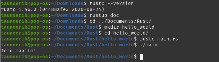
Cargo on programm, mis aitab hallata ja ehitada keerulisemaid projekte. On paketihaldur ja installib teeke = libraries.
Uue projekti tegemine Cargo abil:
$ cargo new hello_cargoProgrammi kompileerimine Cargo abil:
$ cargo buildKäivitatav fail luuakse target/debug/ kausta.
Käivita:
$ cargo run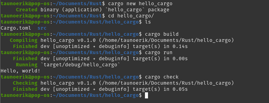
Loob välajalaske:
$ cargo build --release$ git clone someurl.com/someproject
$ cd someproject
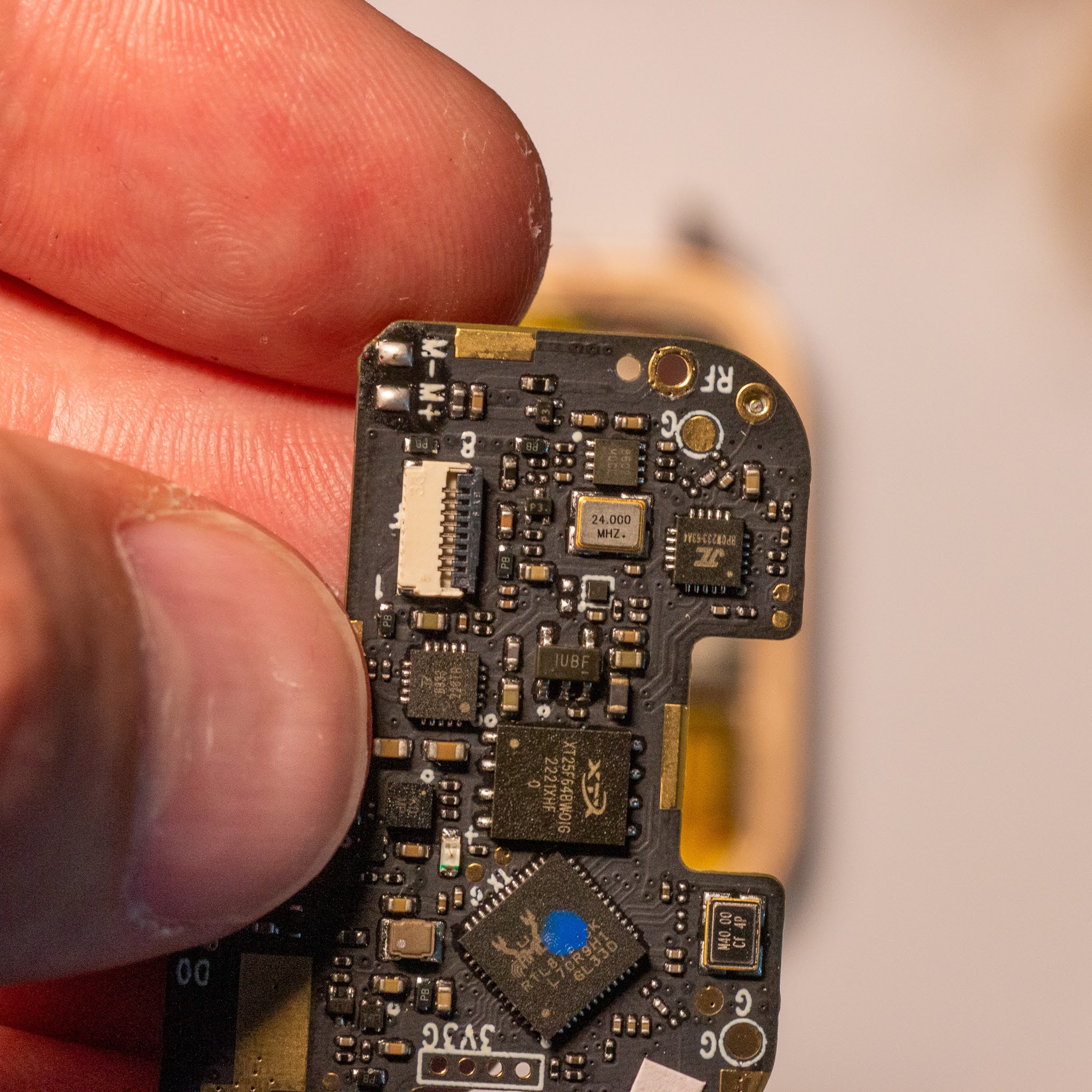
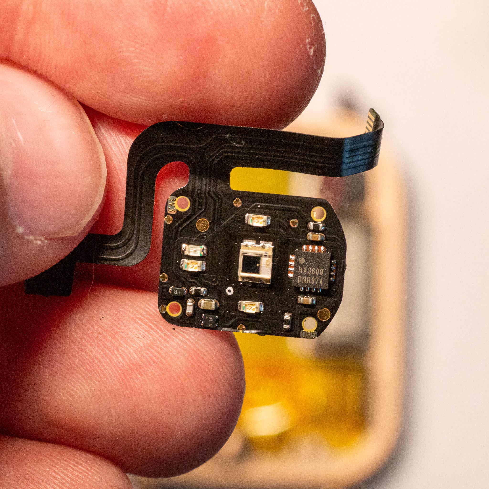
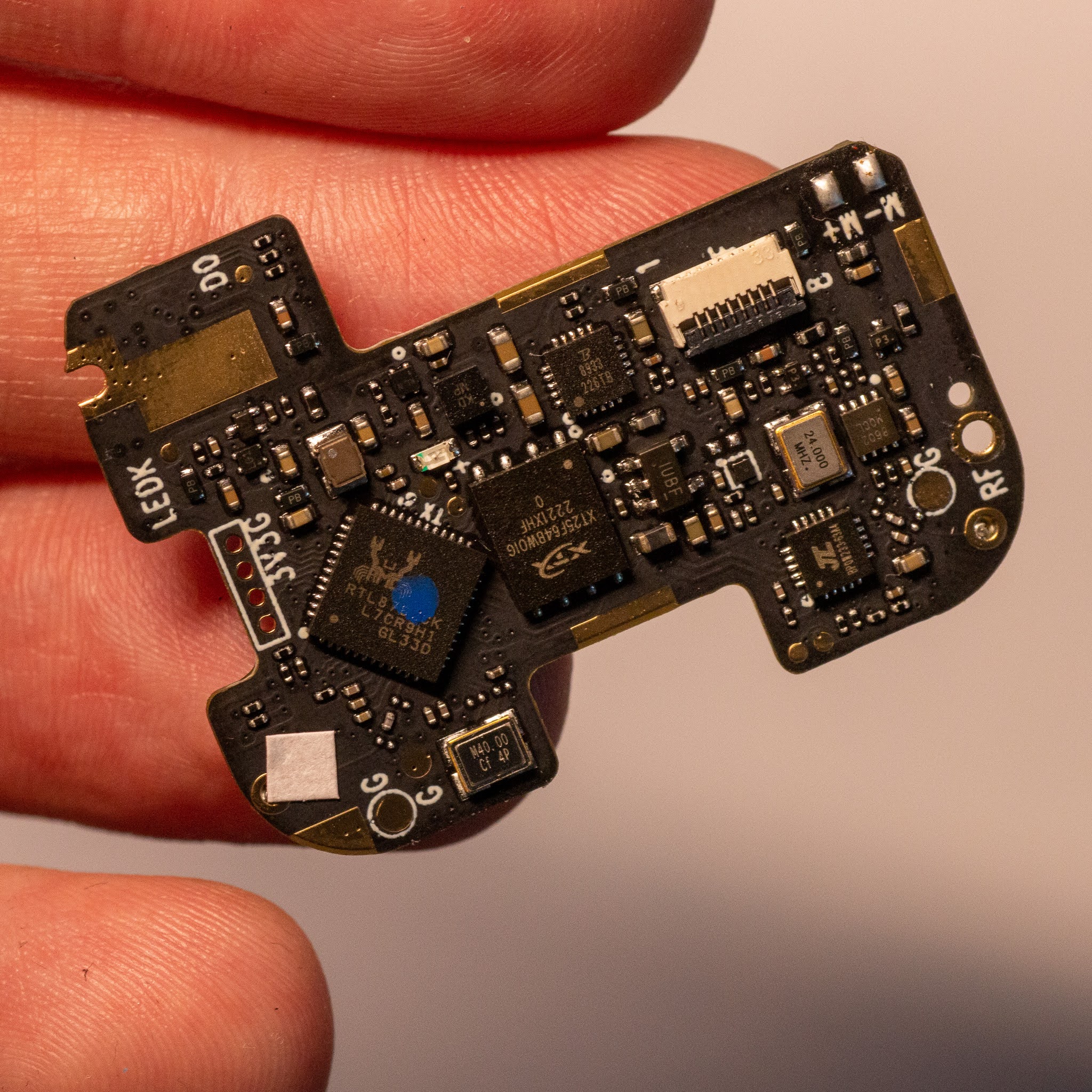
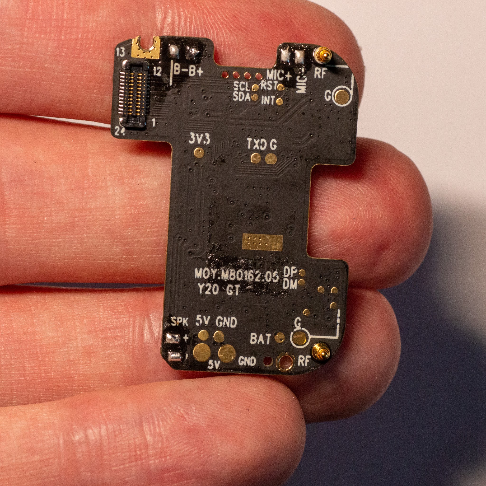
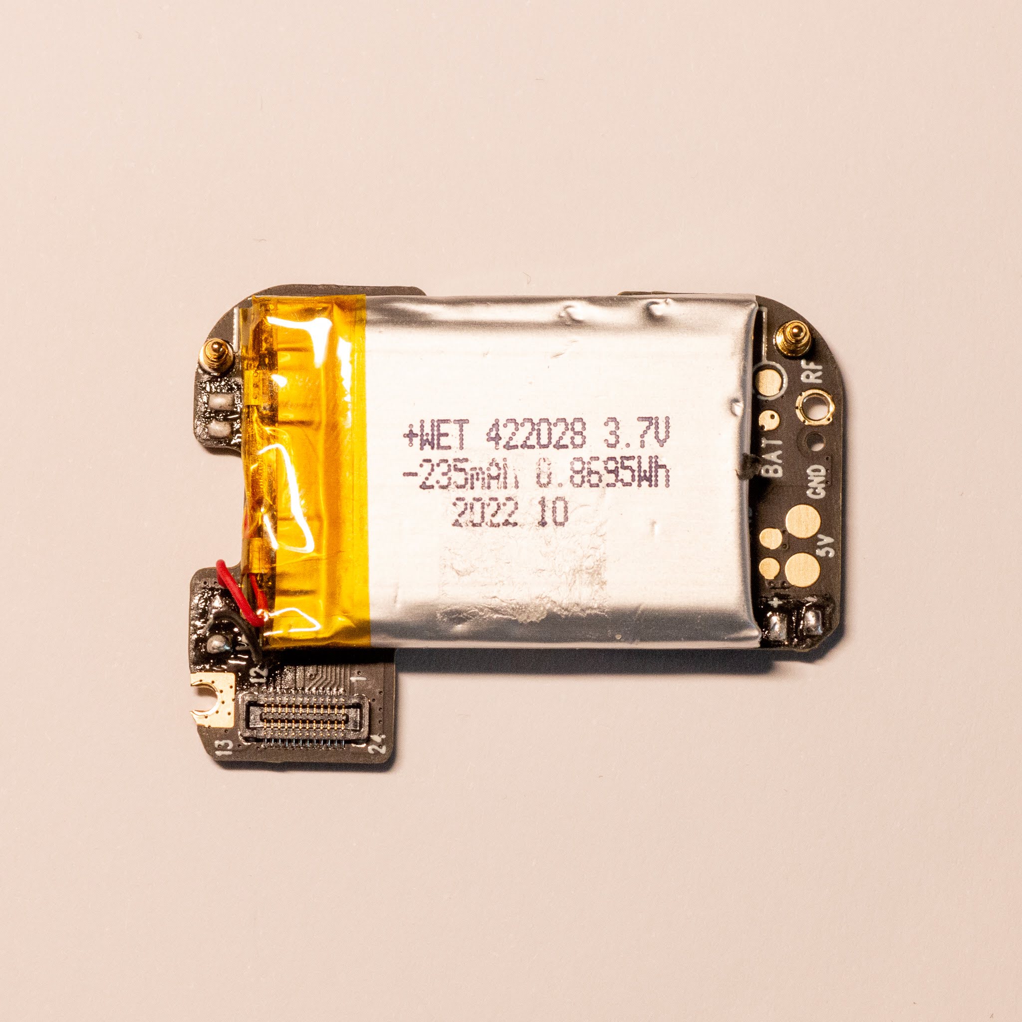
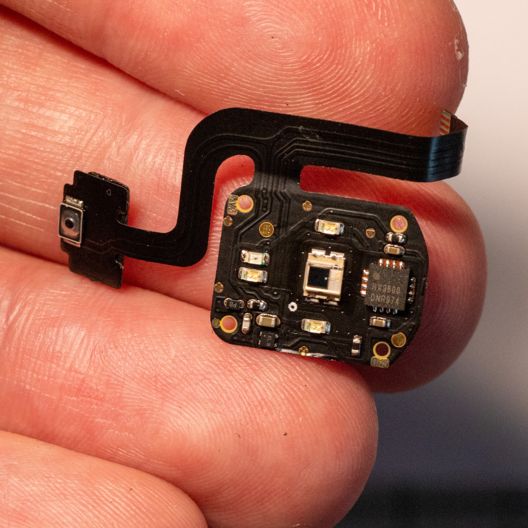
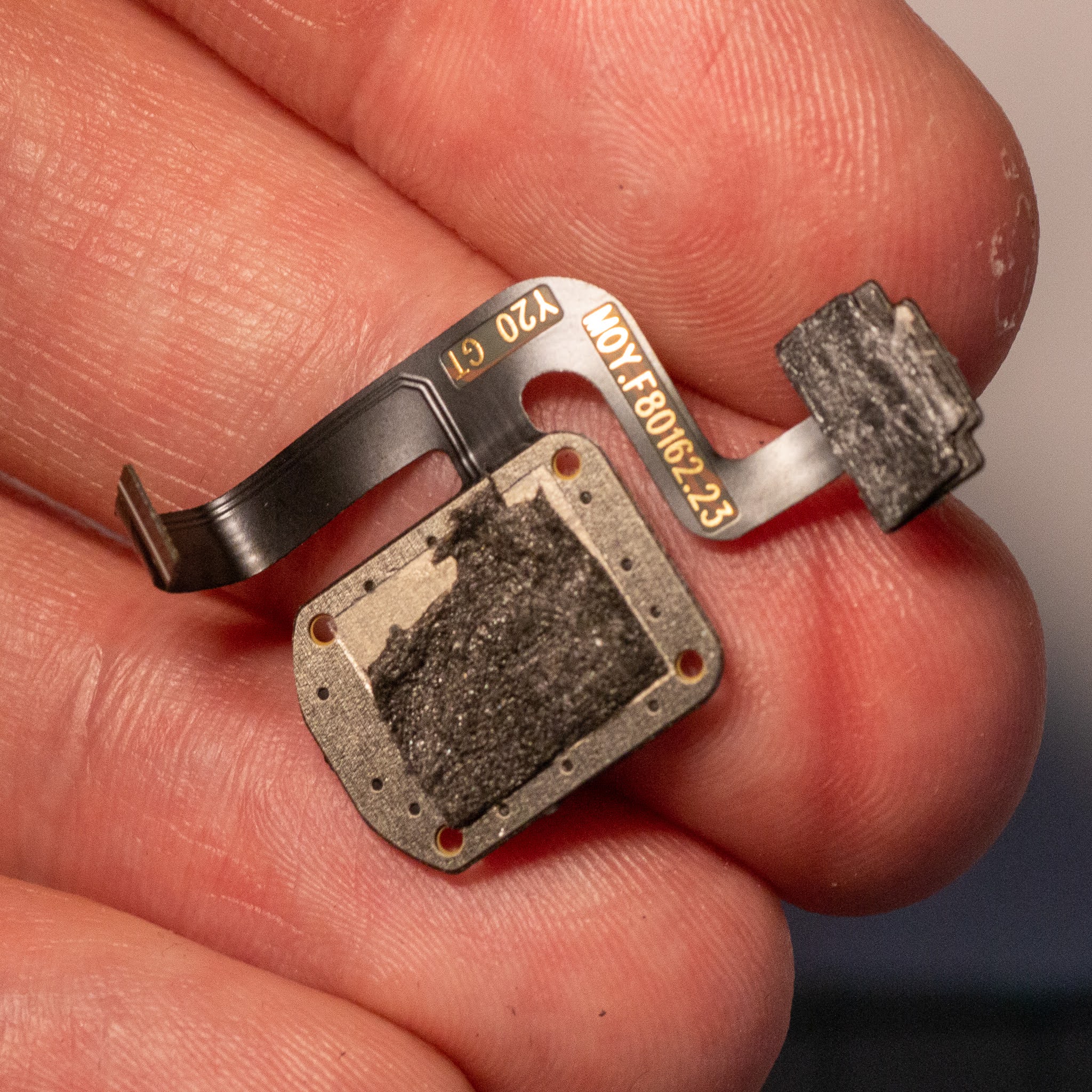
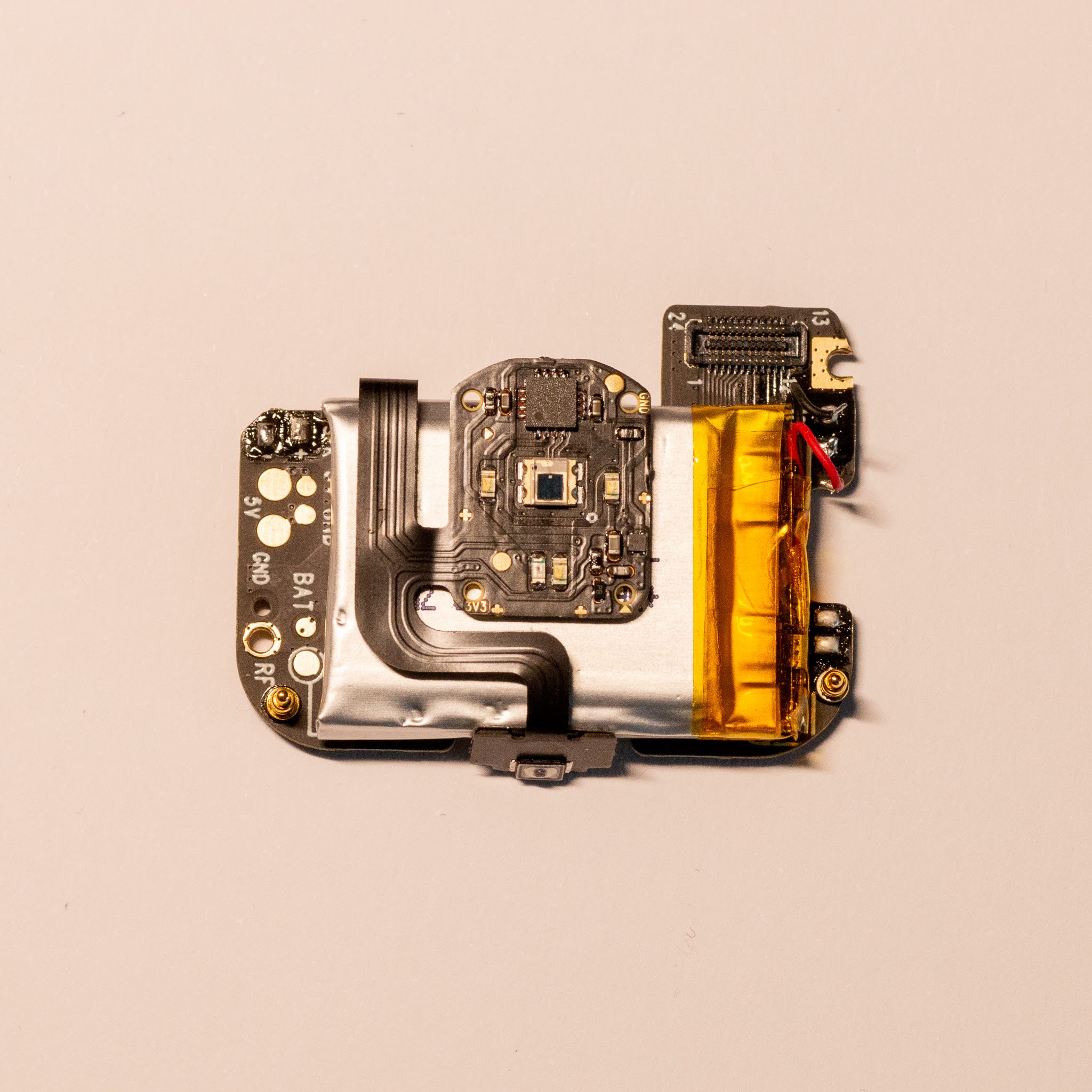
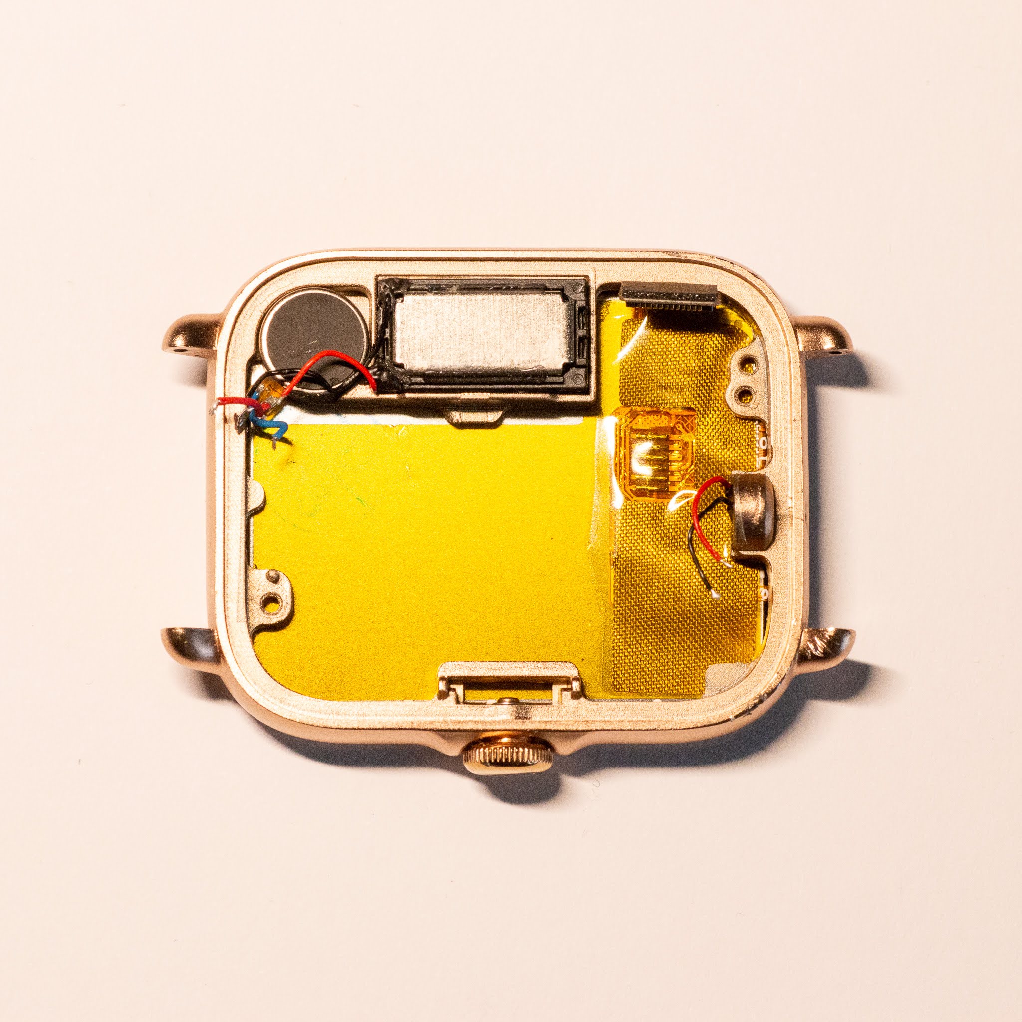
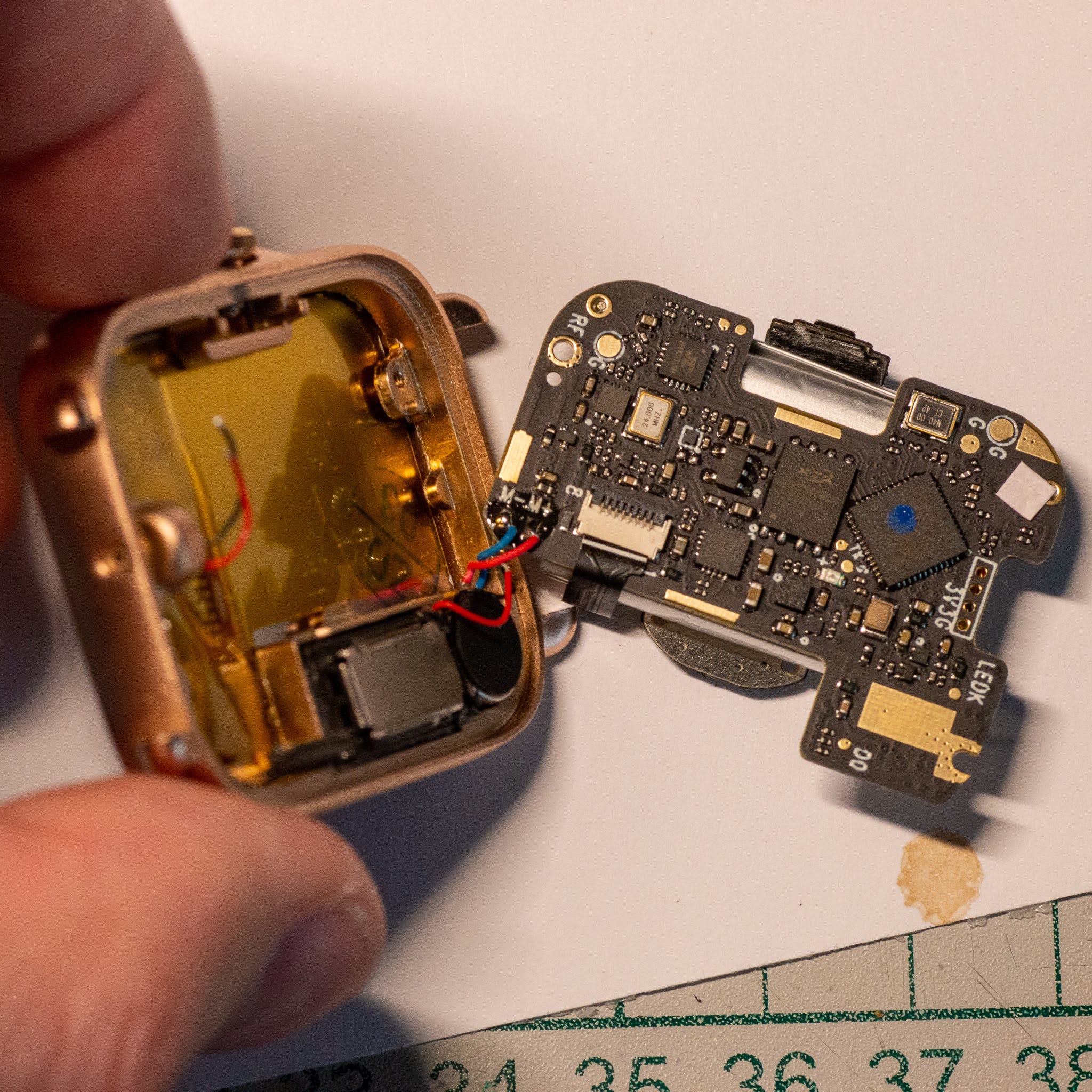
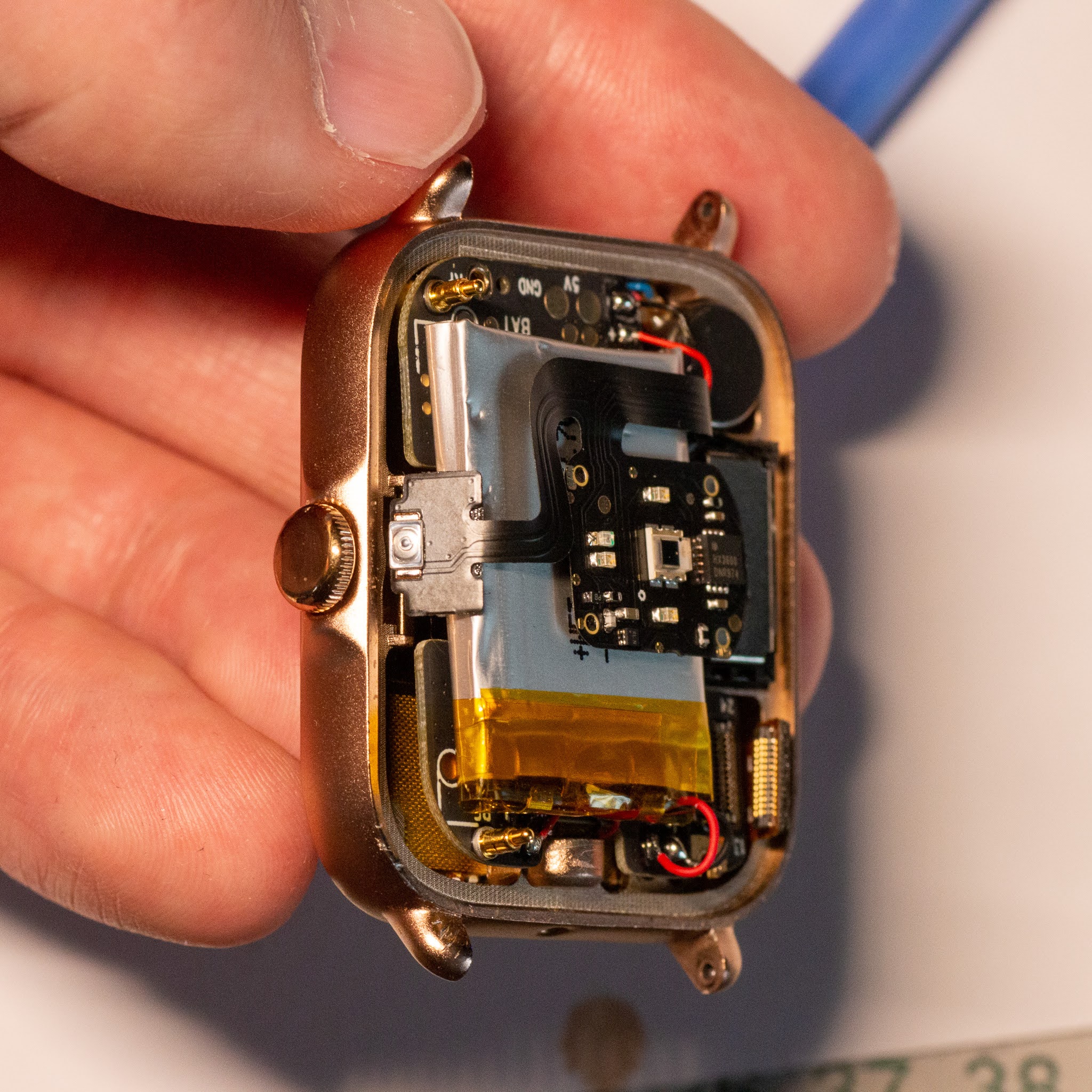
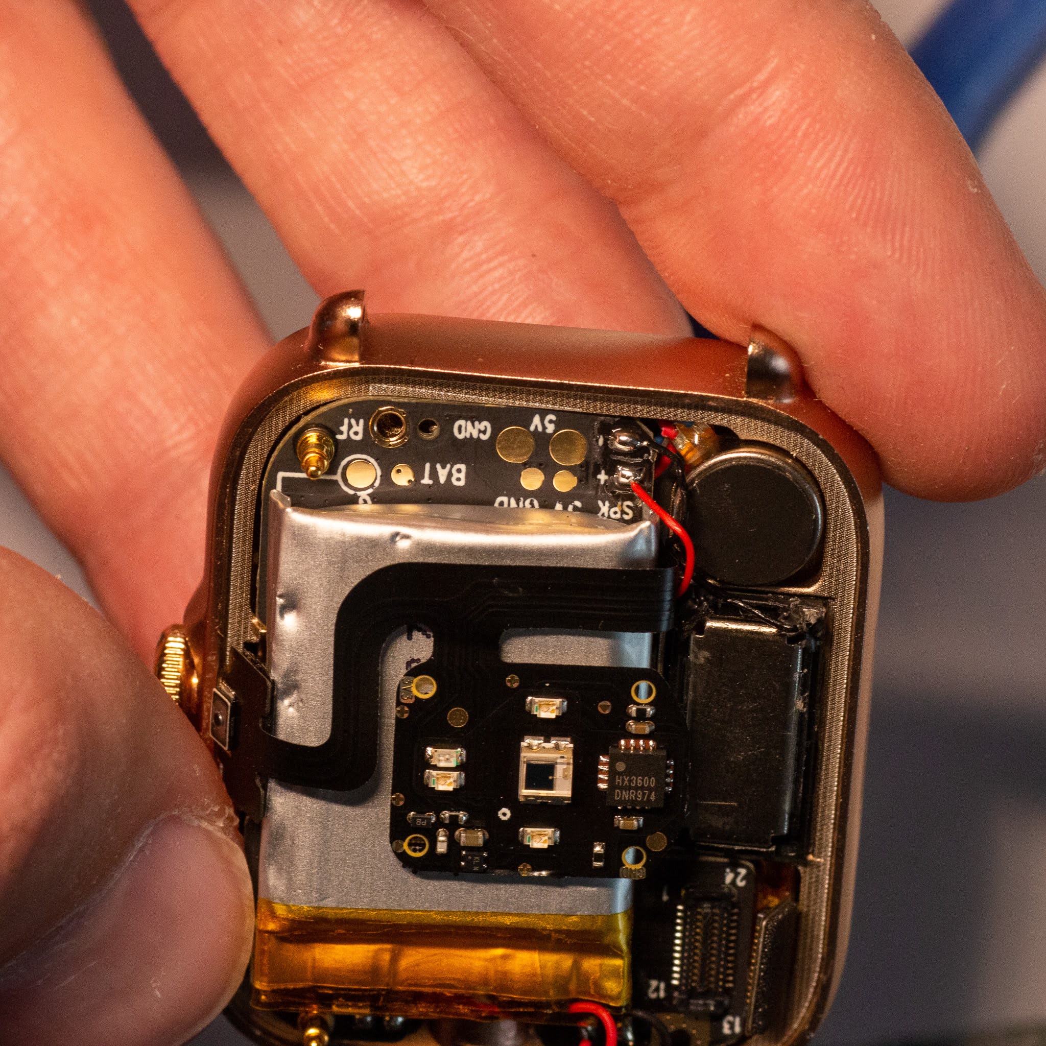
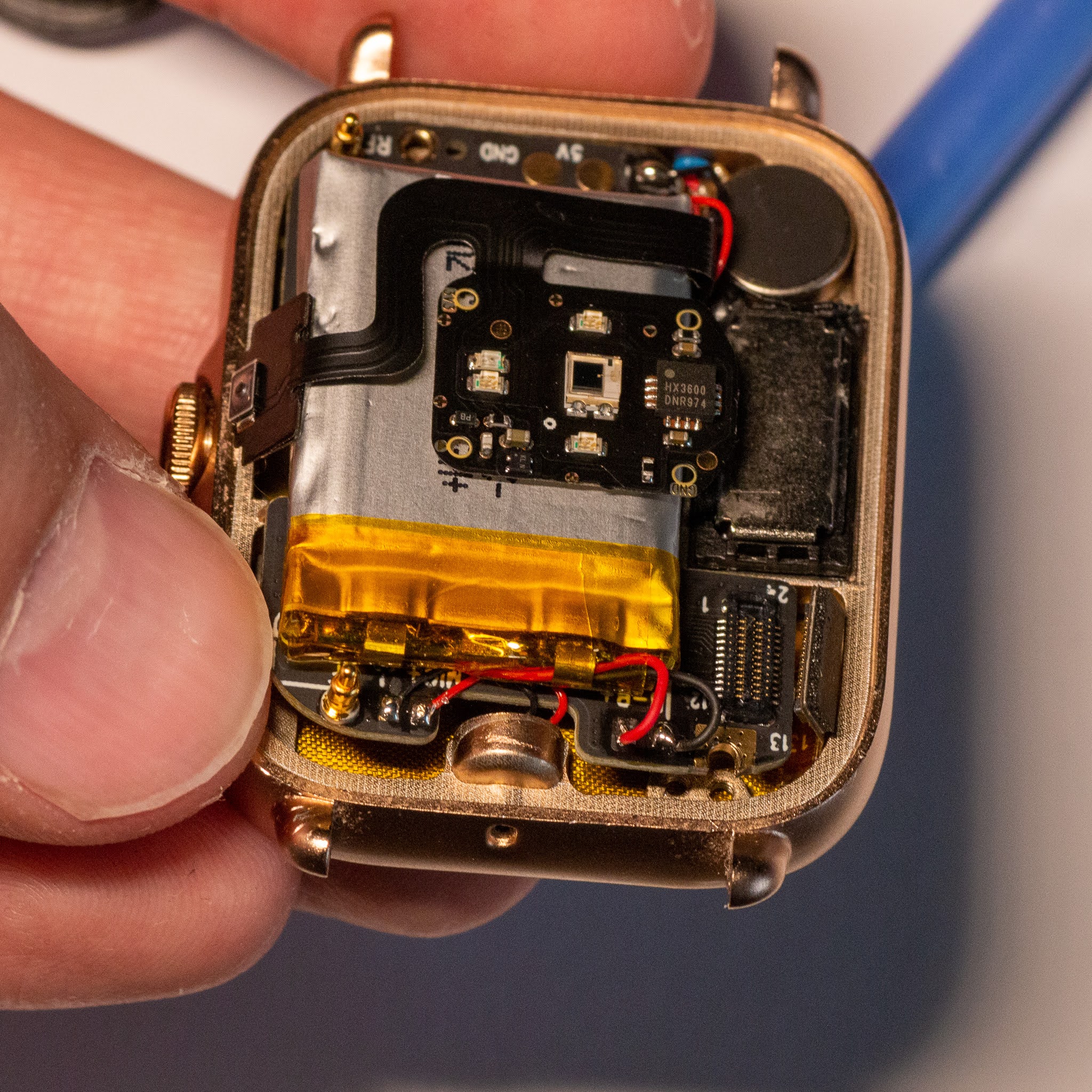
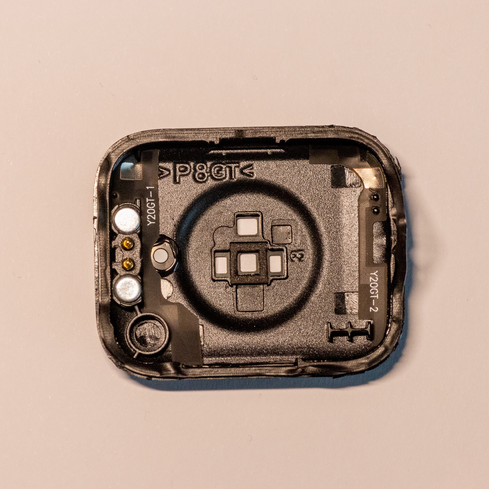
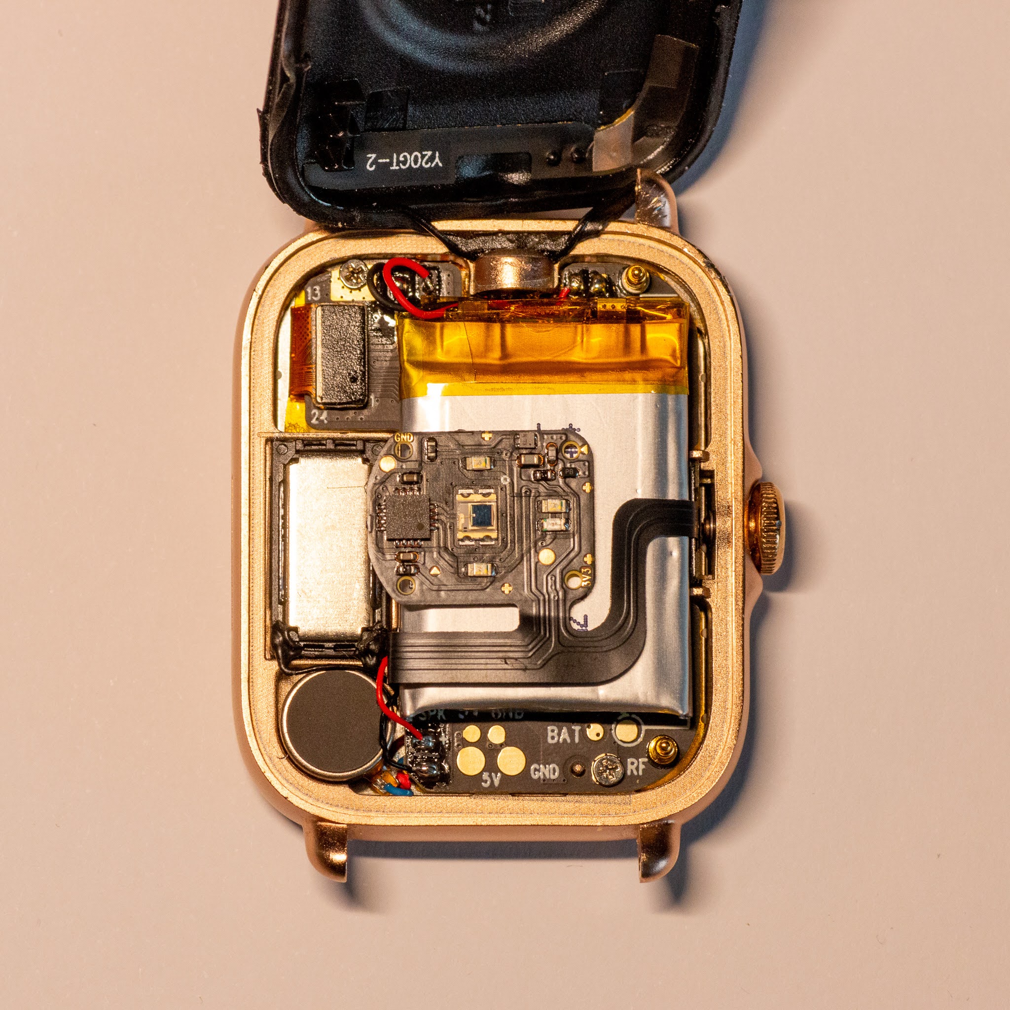
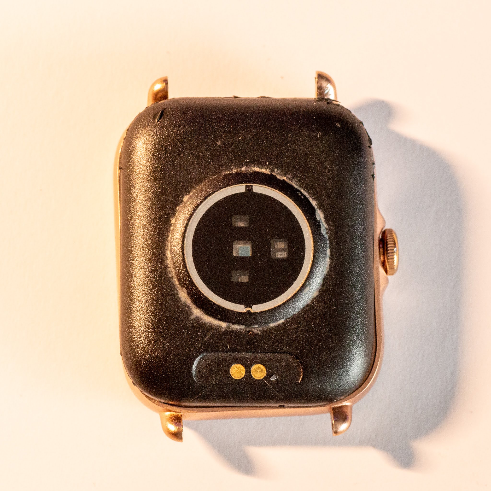
$ cargo buildI recently took it apart this Y22 Smart Watch and will document all images here just in case. The screen glass was already broken.

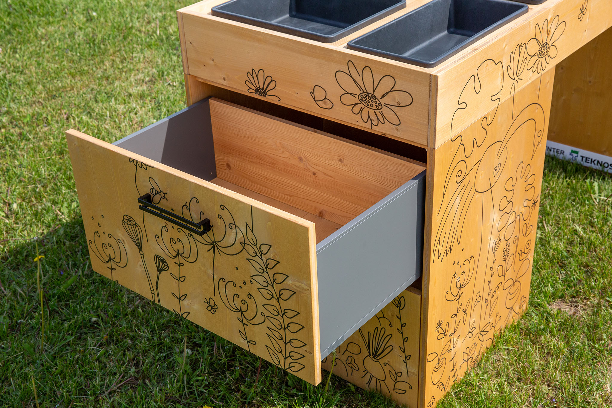
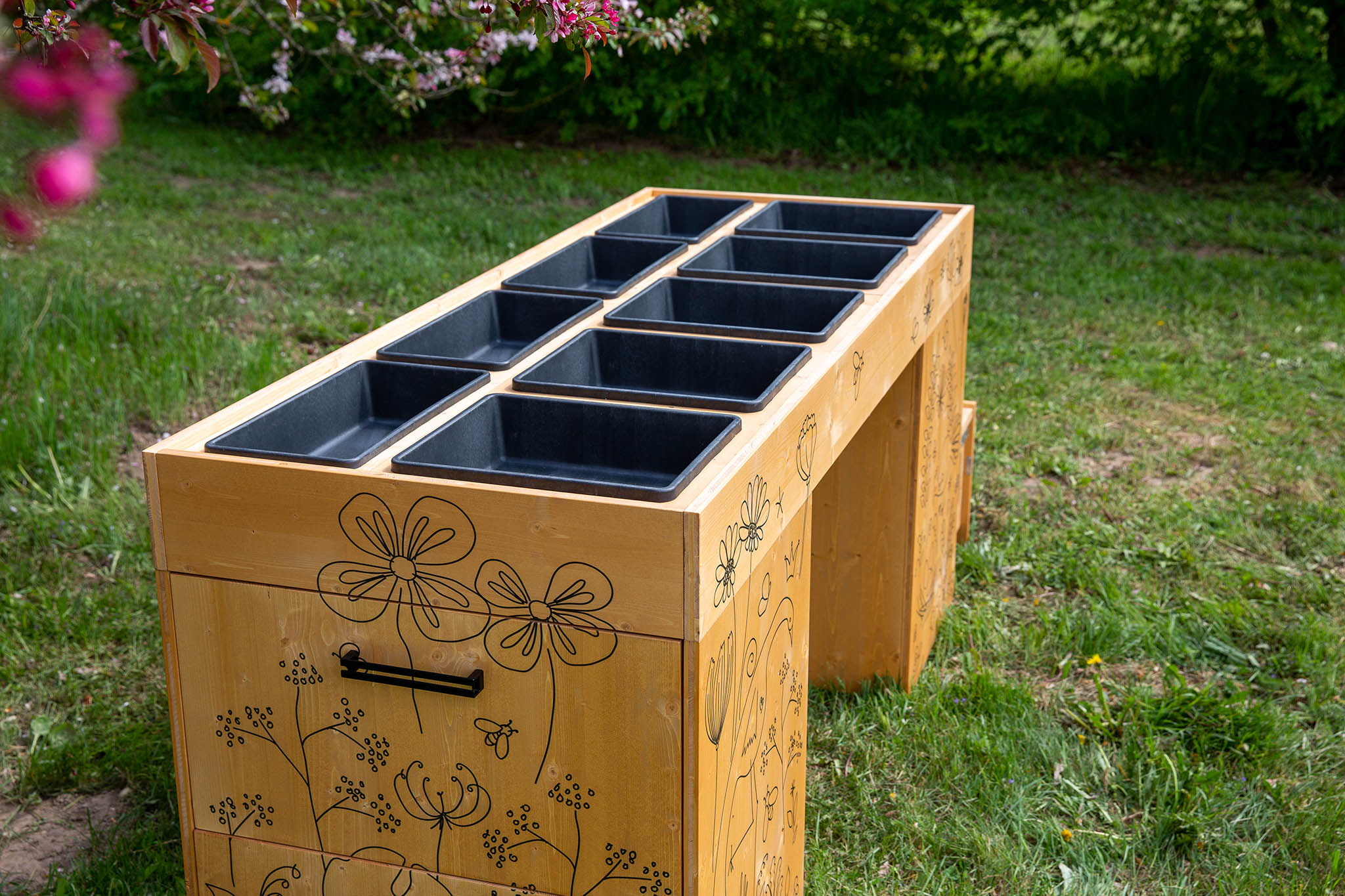
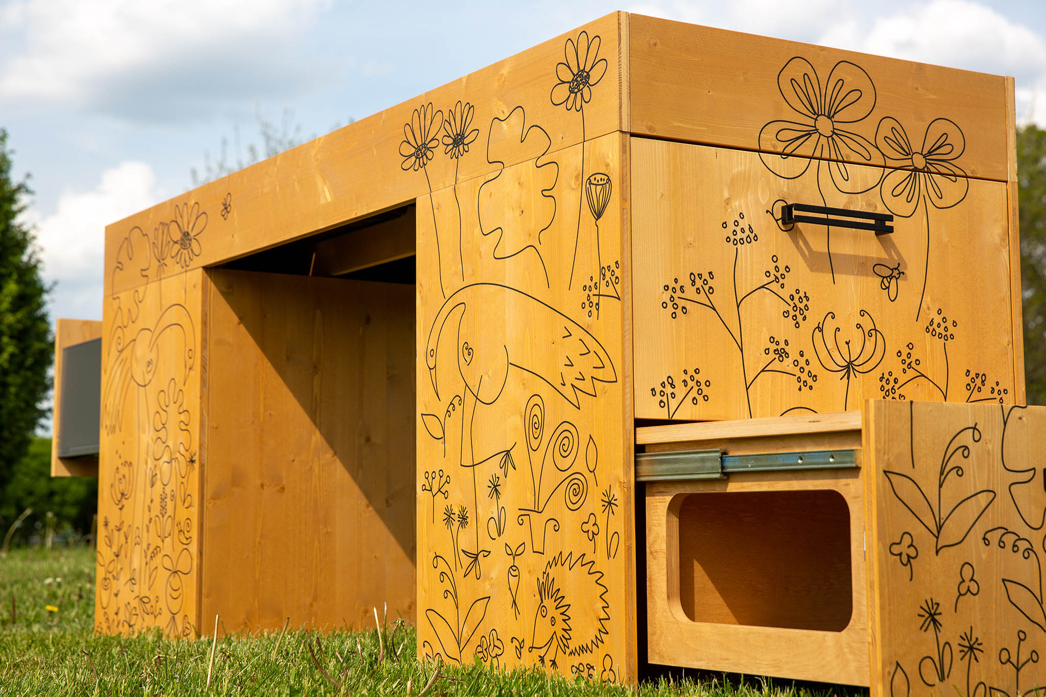
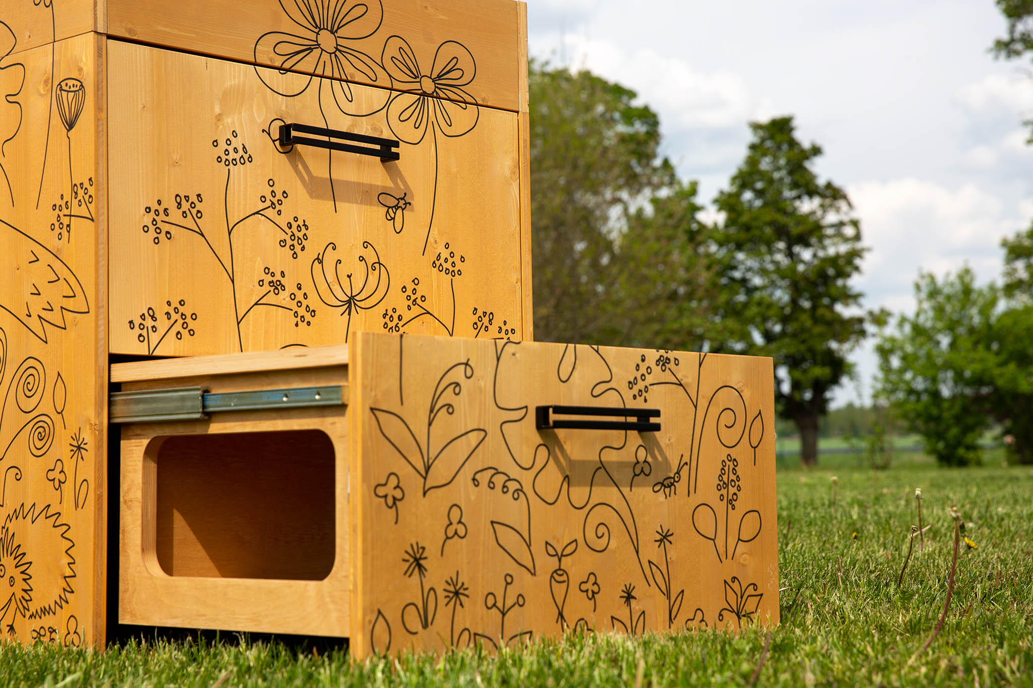
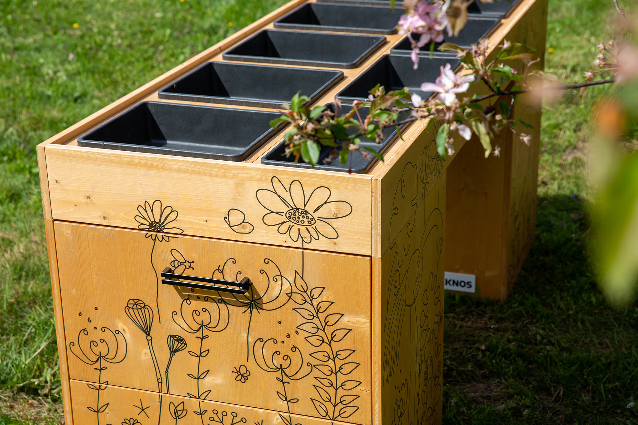
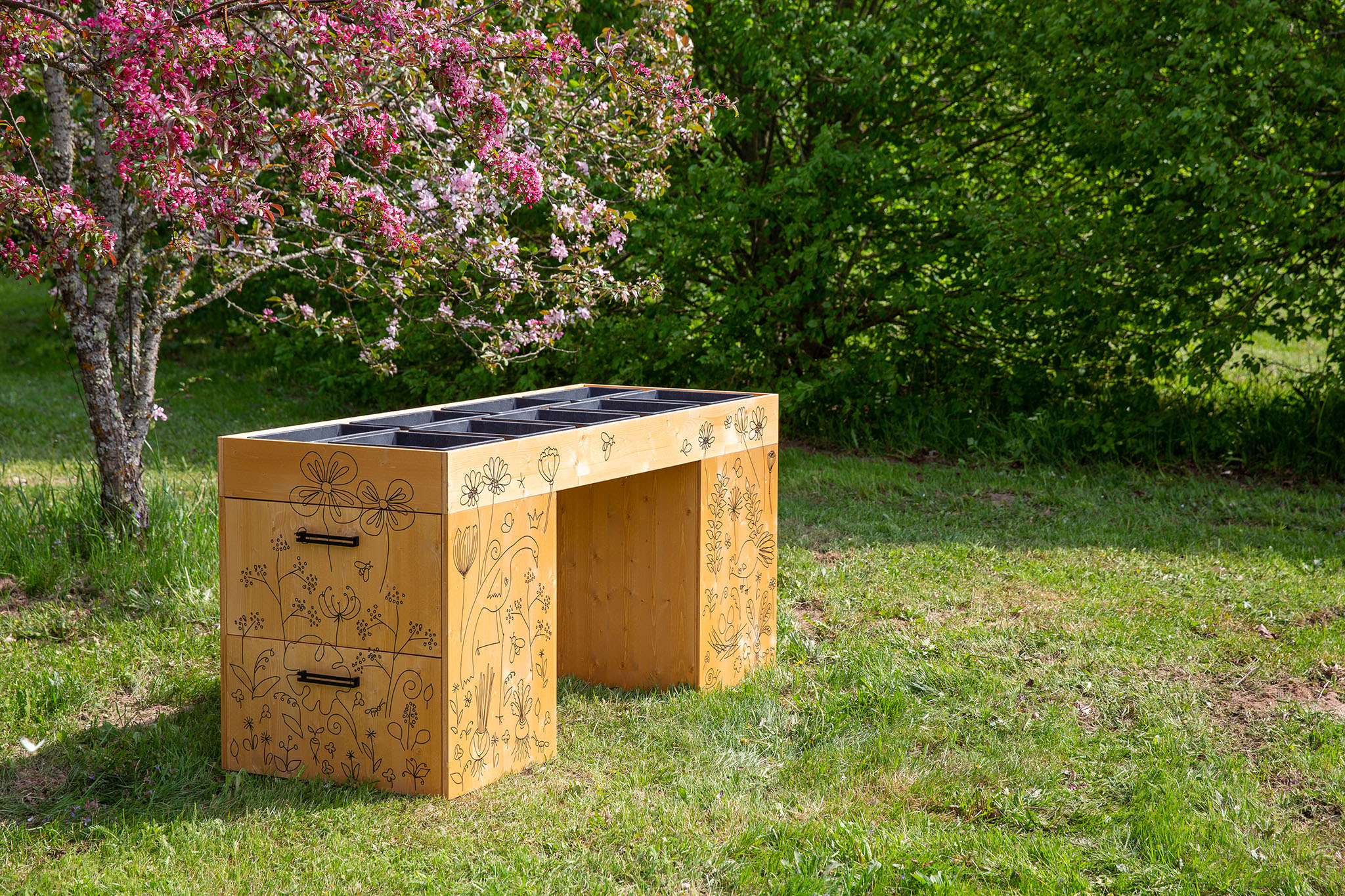
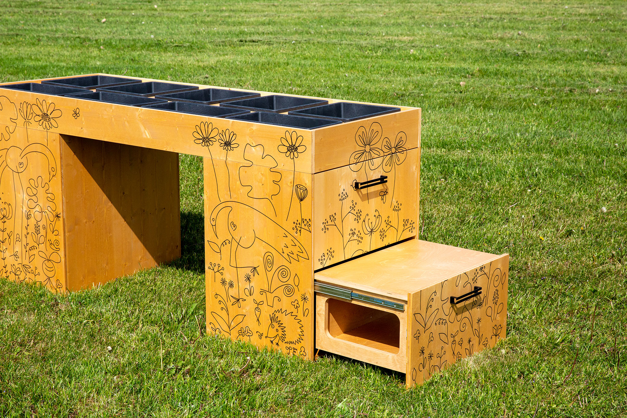
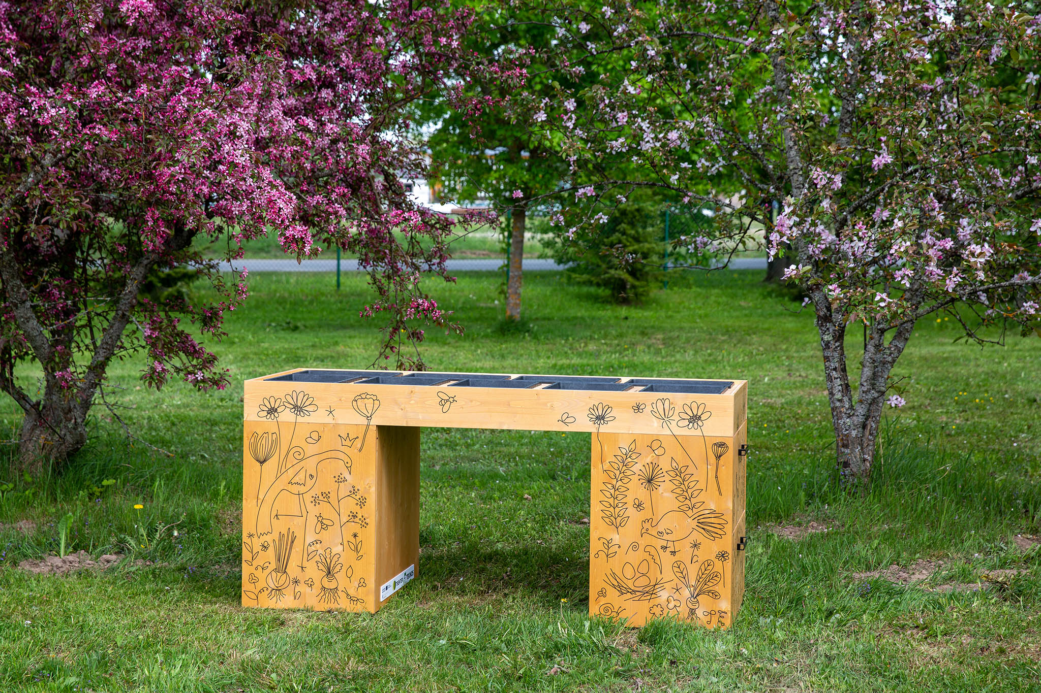
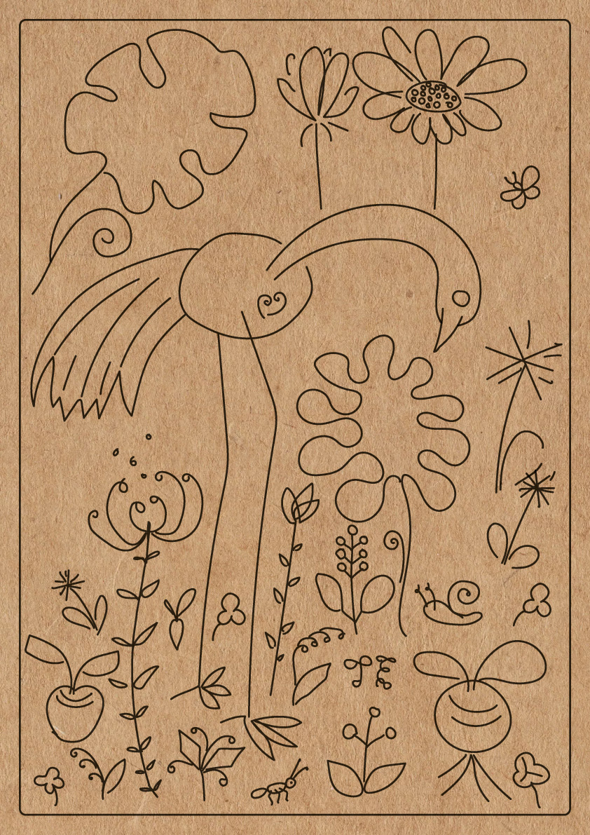
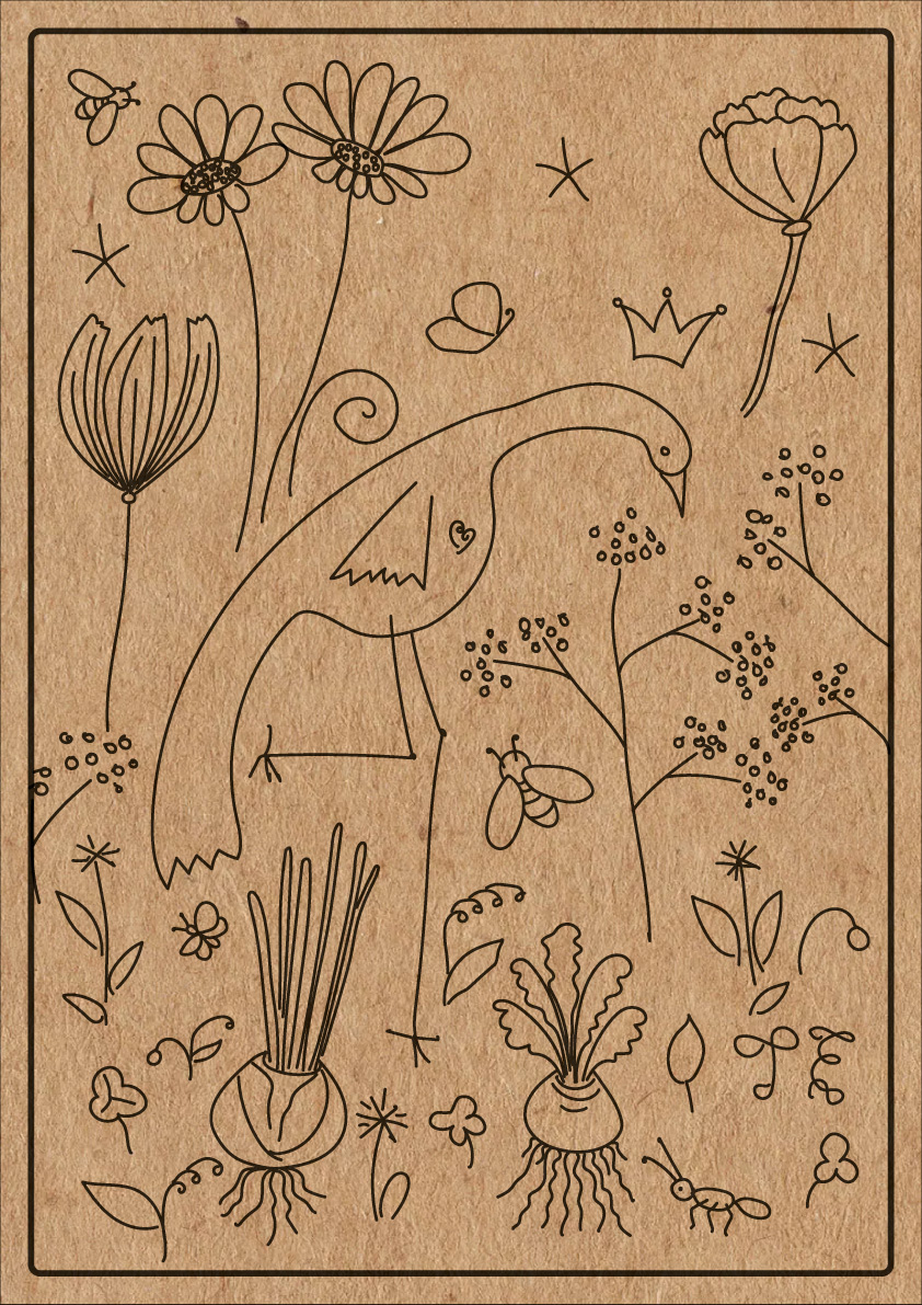
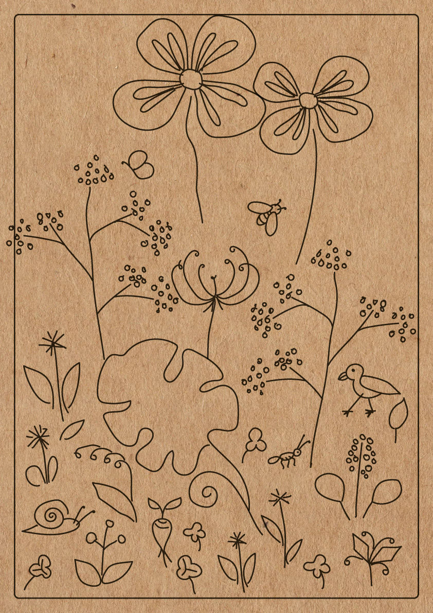
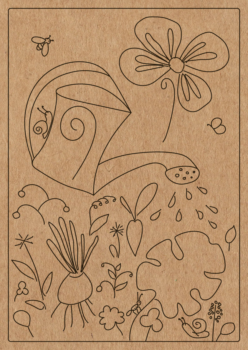
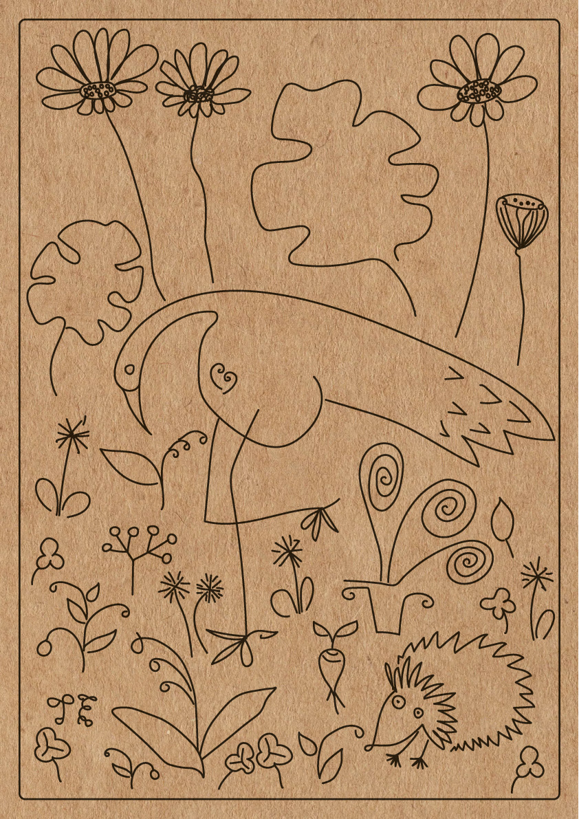
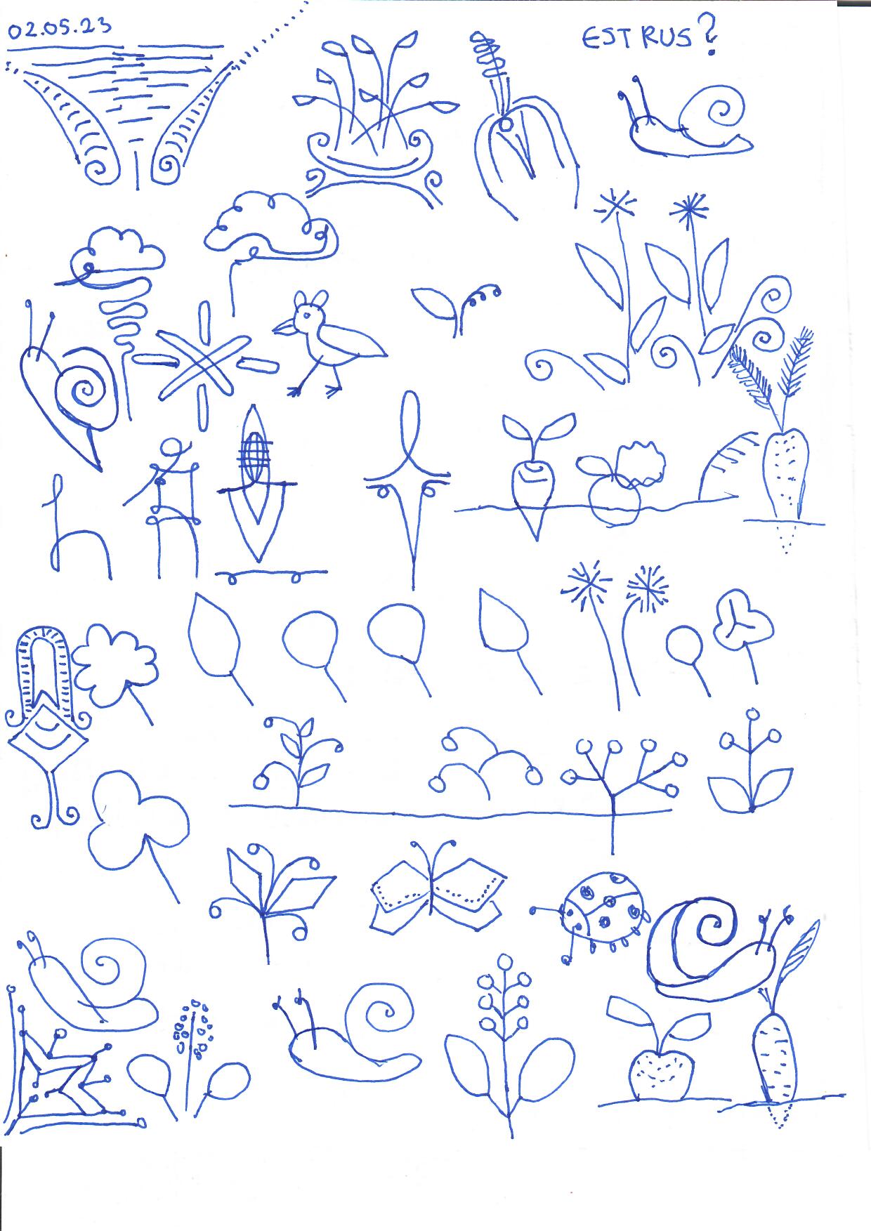
My drawings on this planting table. First I drew on paper. Then I drew over the vector format. Printed on wood.
The planter table/chest allows several generations to grow plants together. The table is designed in such a way that even a person in a wheelchair can move around it. In addition, children can help by using a special extendable standing platform that is cleverly hidden in a drawer. KidsLikeUs is a new international INTERREG Baltic Sea region project where TSENTER participates as a partner.

Vectorized versions
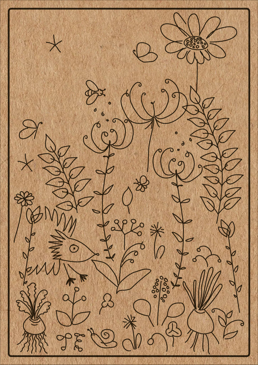
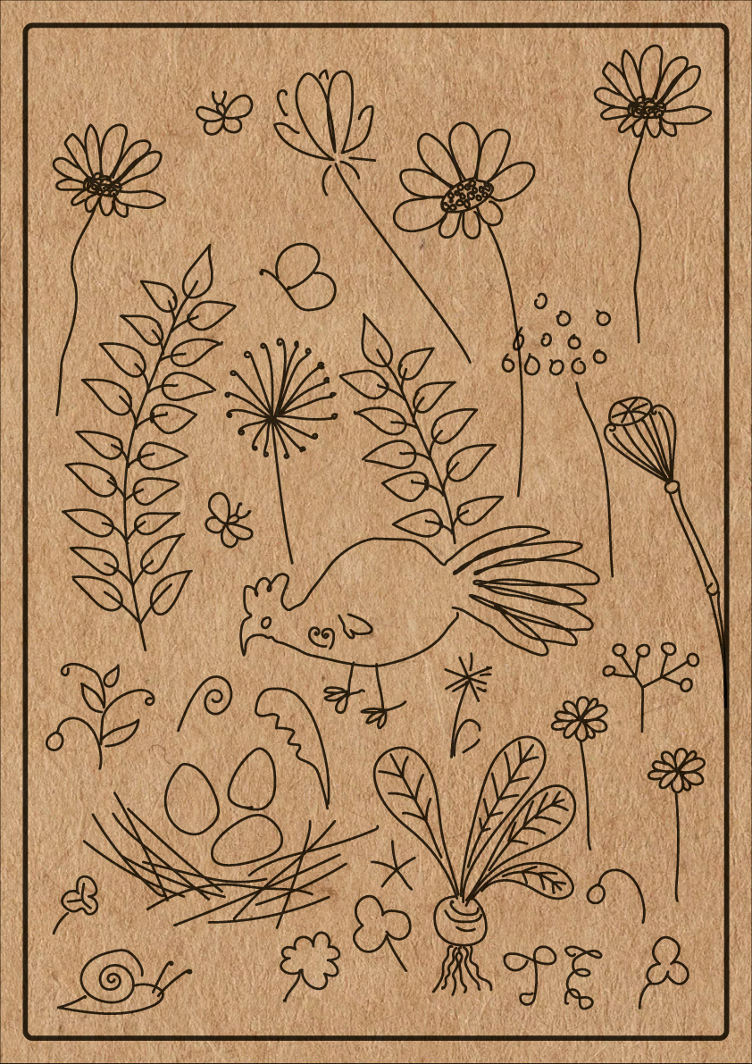
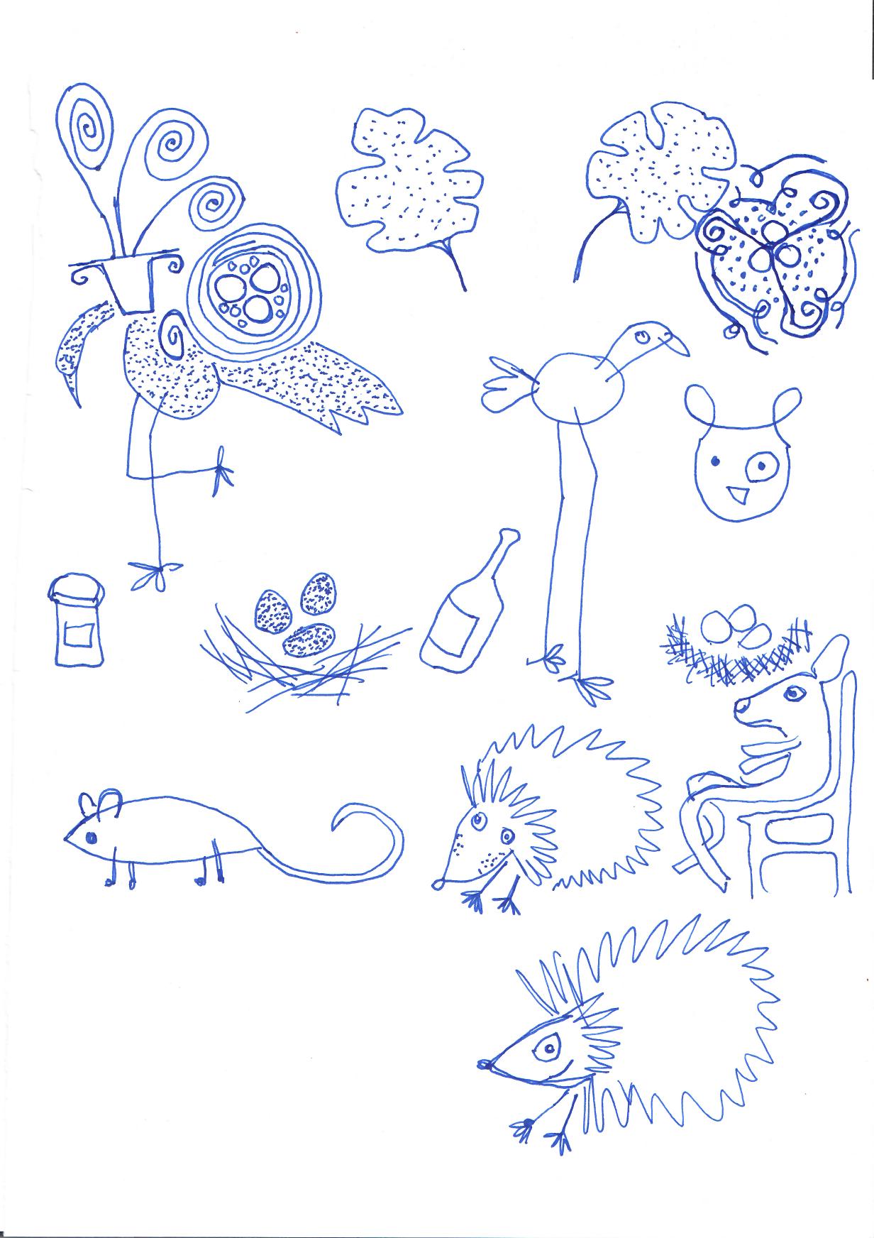
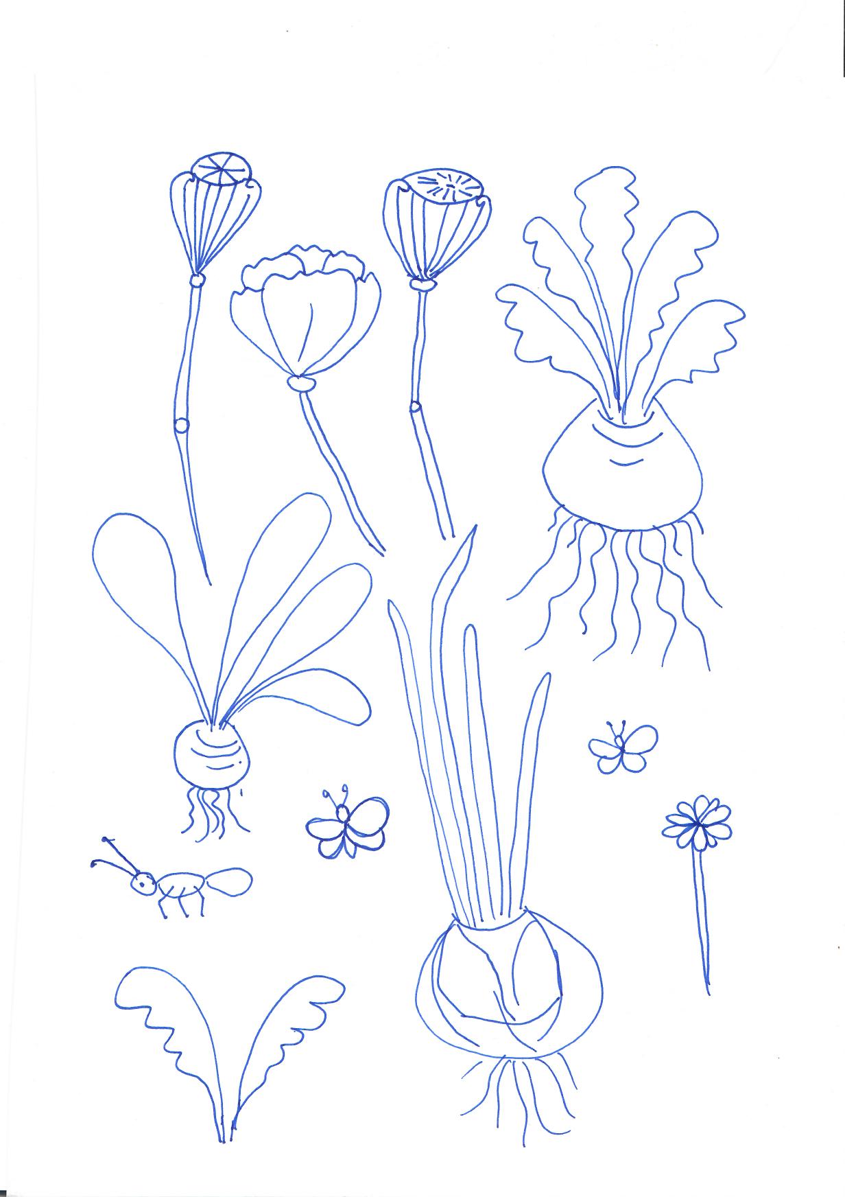
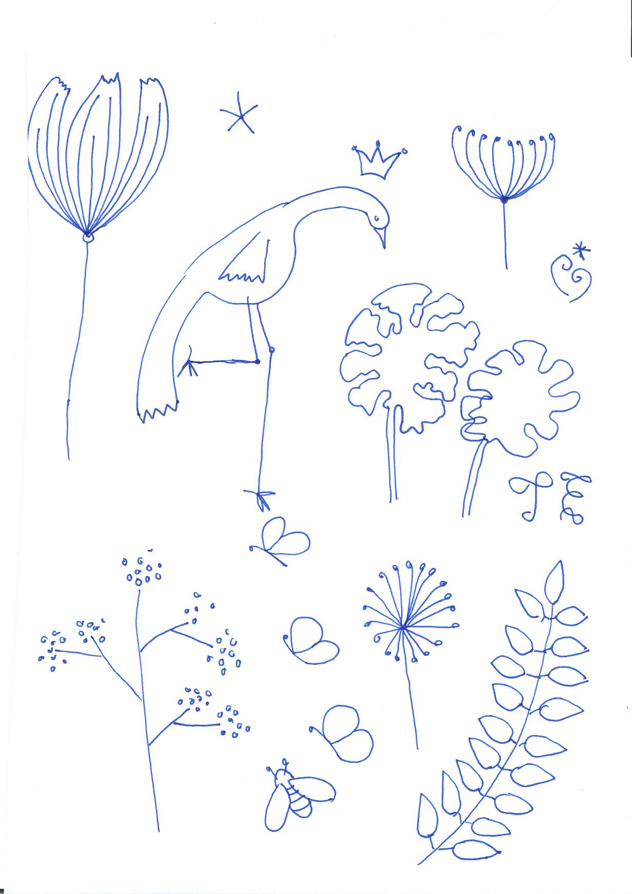
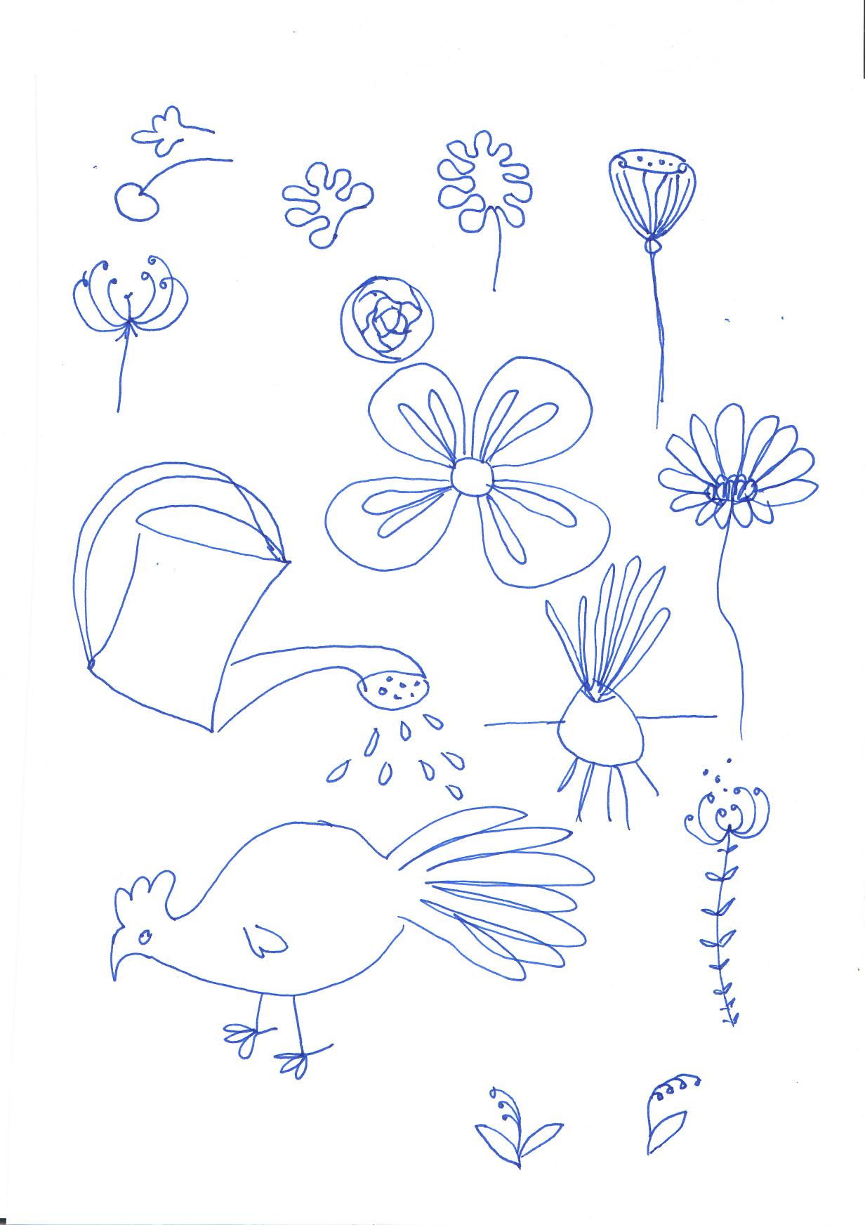
Original drawings, pen on paper:
Esmalt avaldatud: tsenter.ee/poordprojekteerimine-kuidas-see-praktikas-kasutust-leiab/
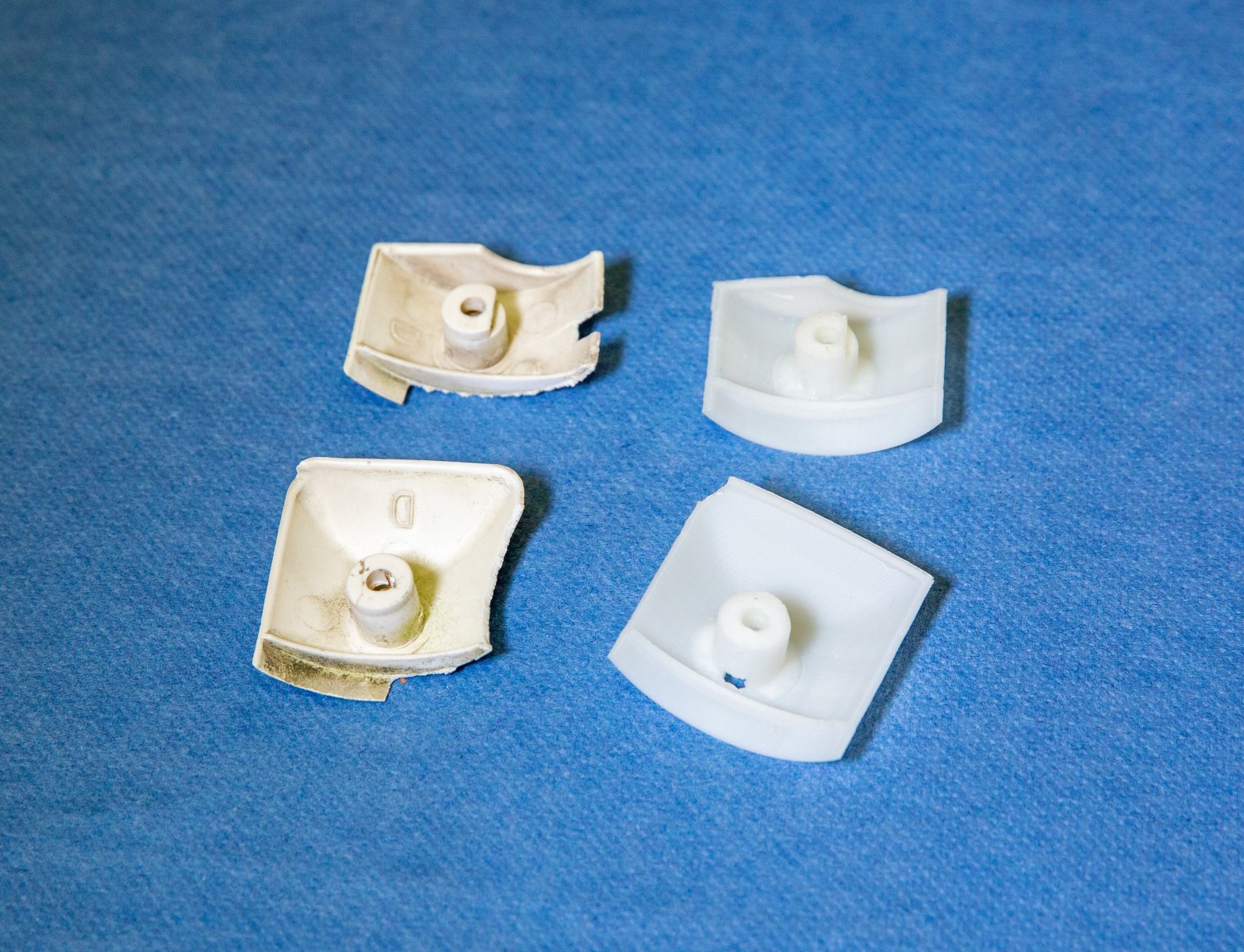
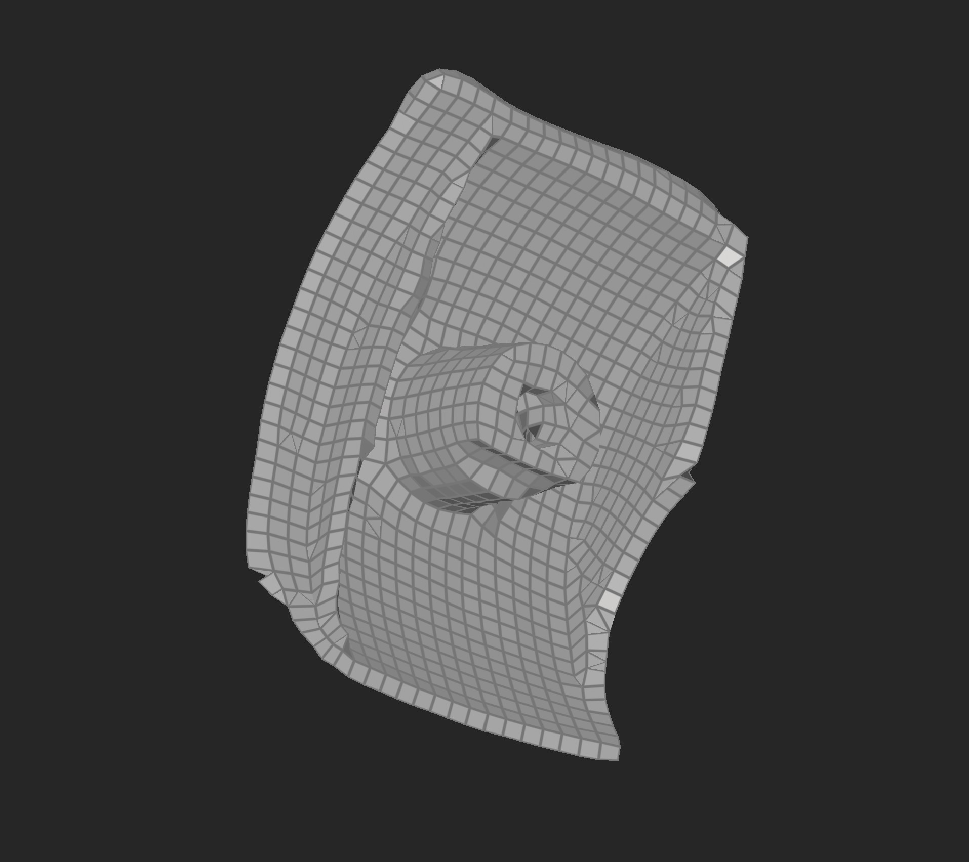
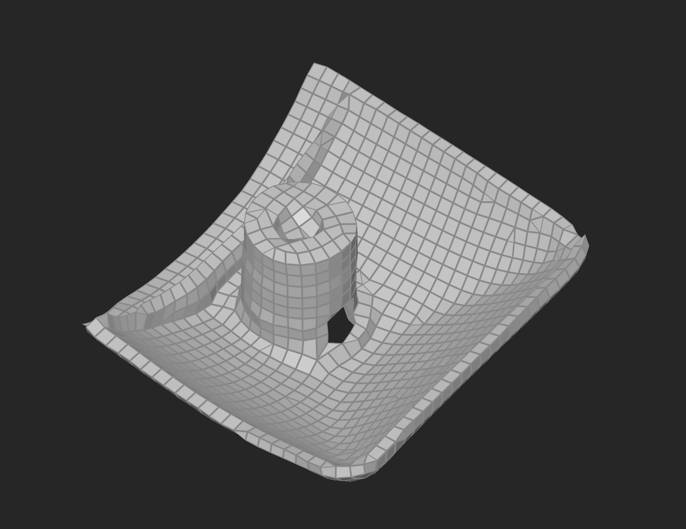
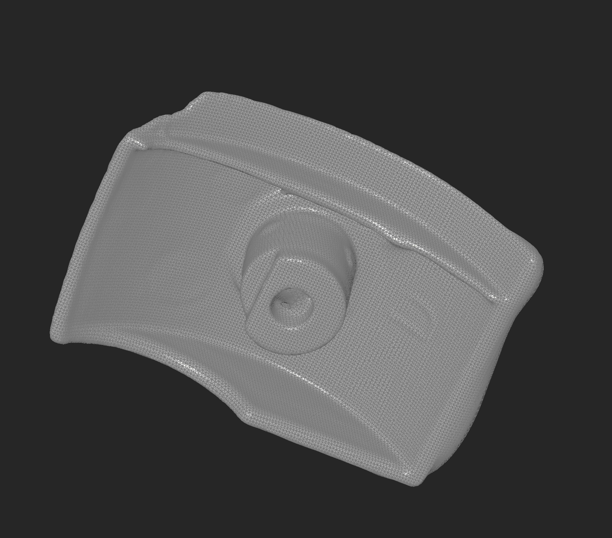
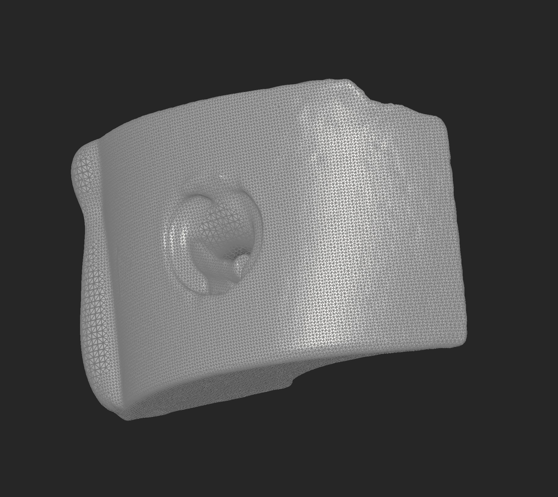
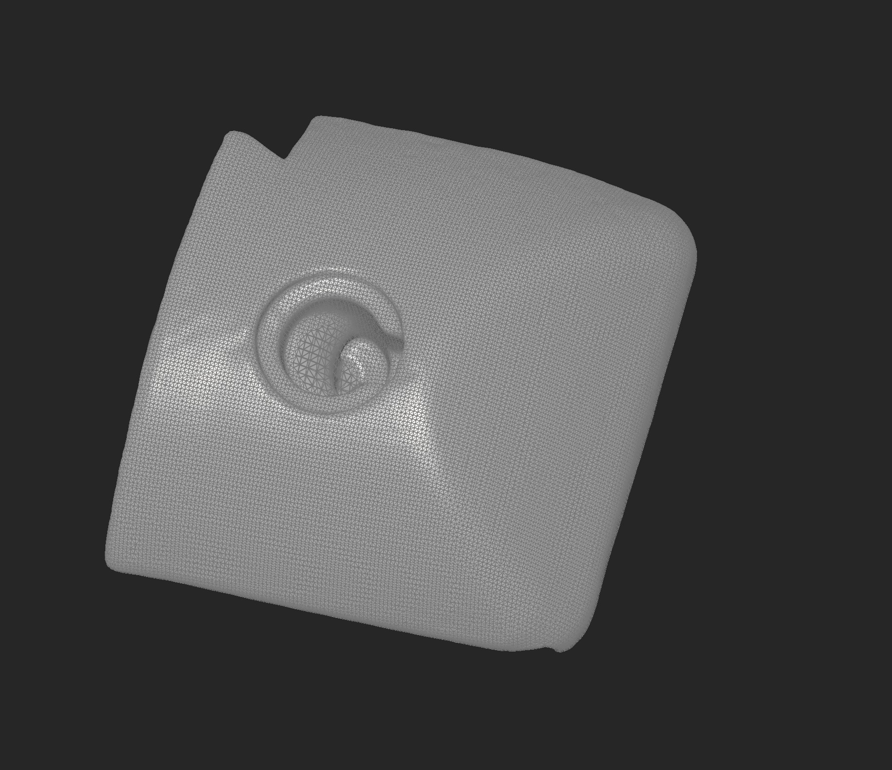
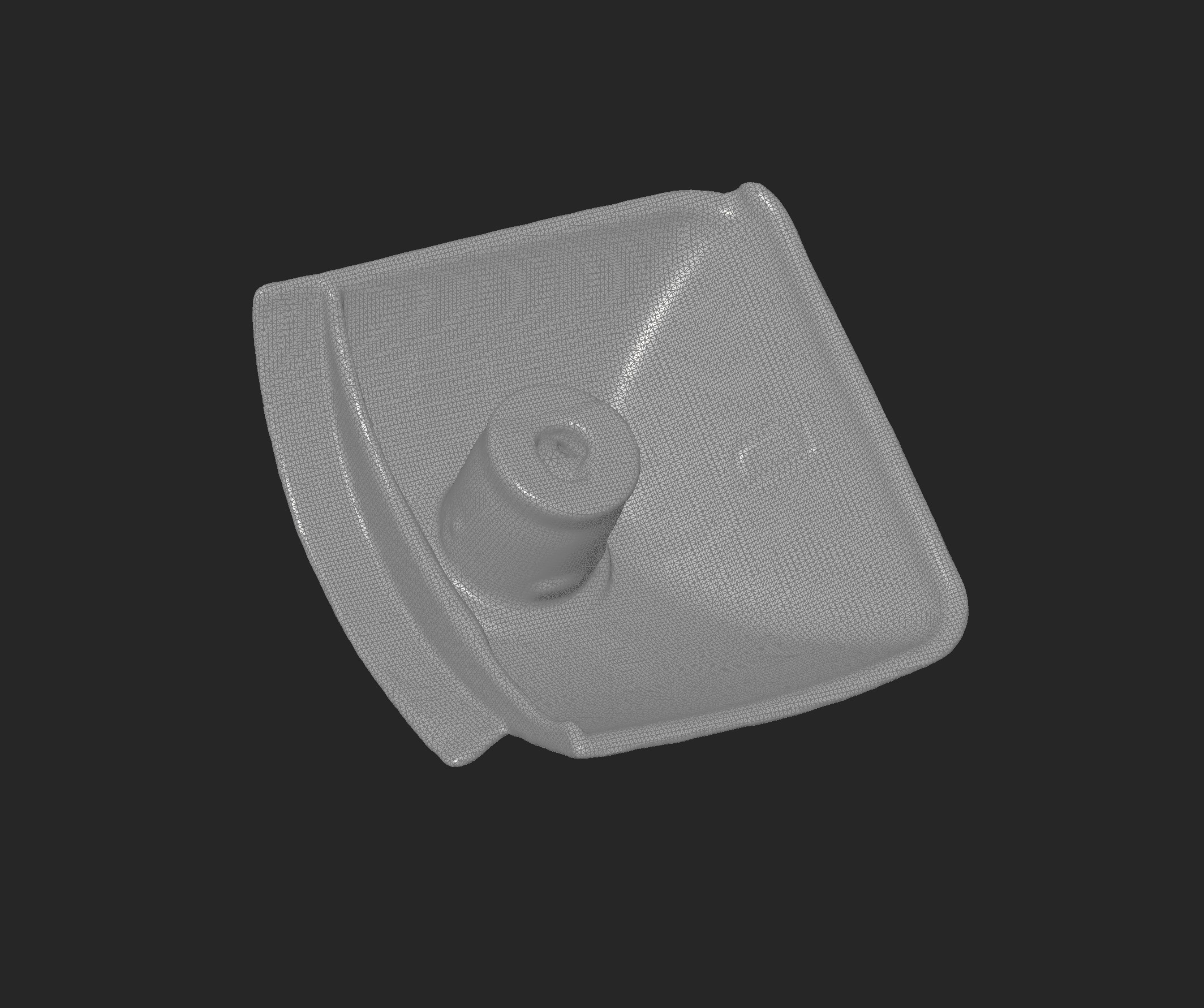
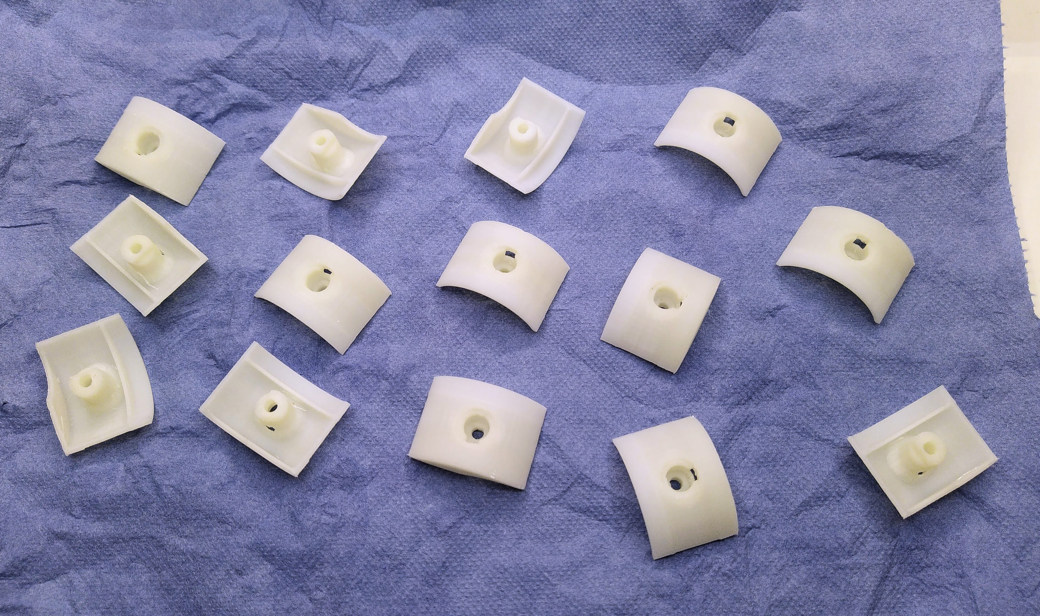
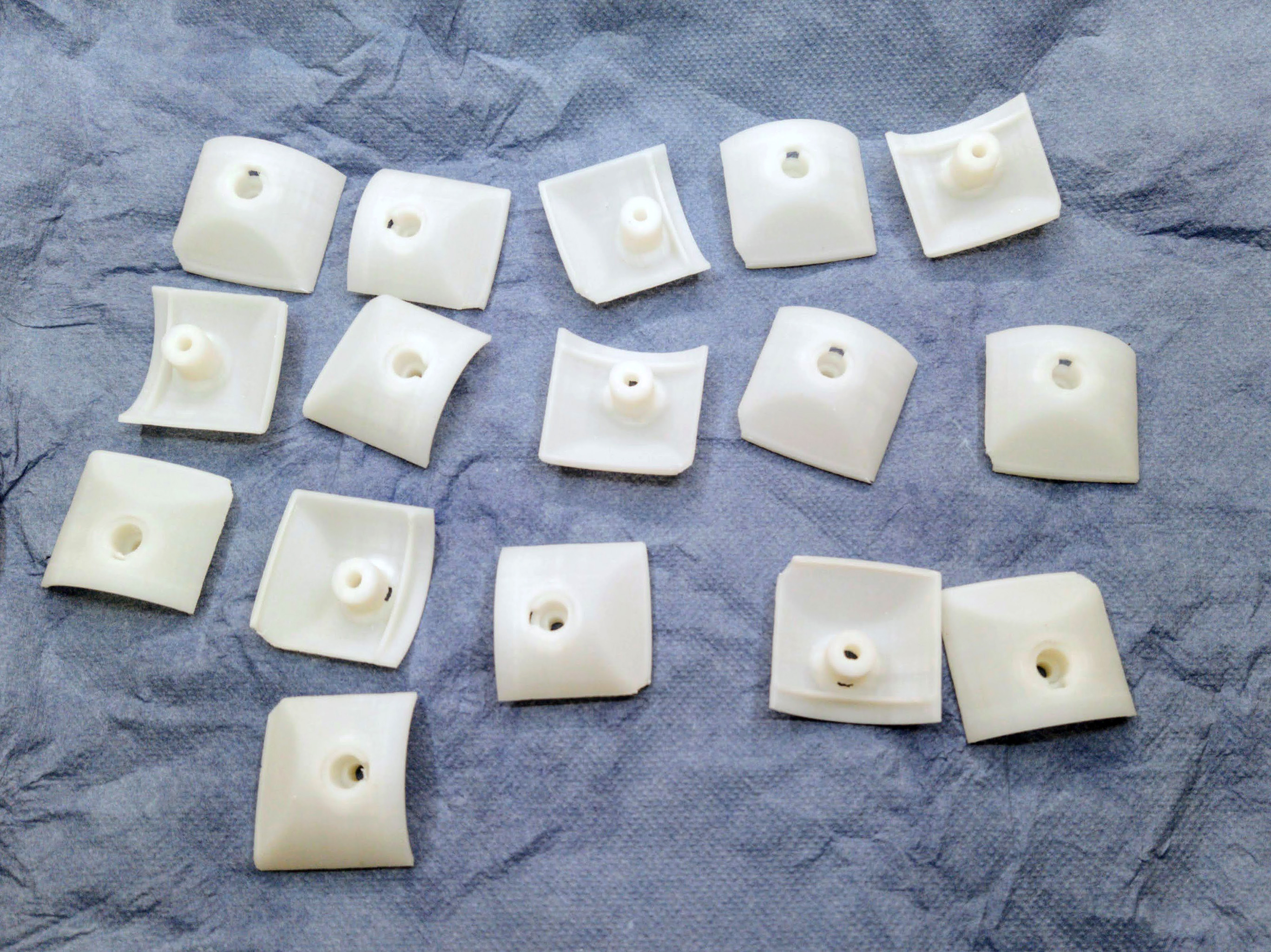
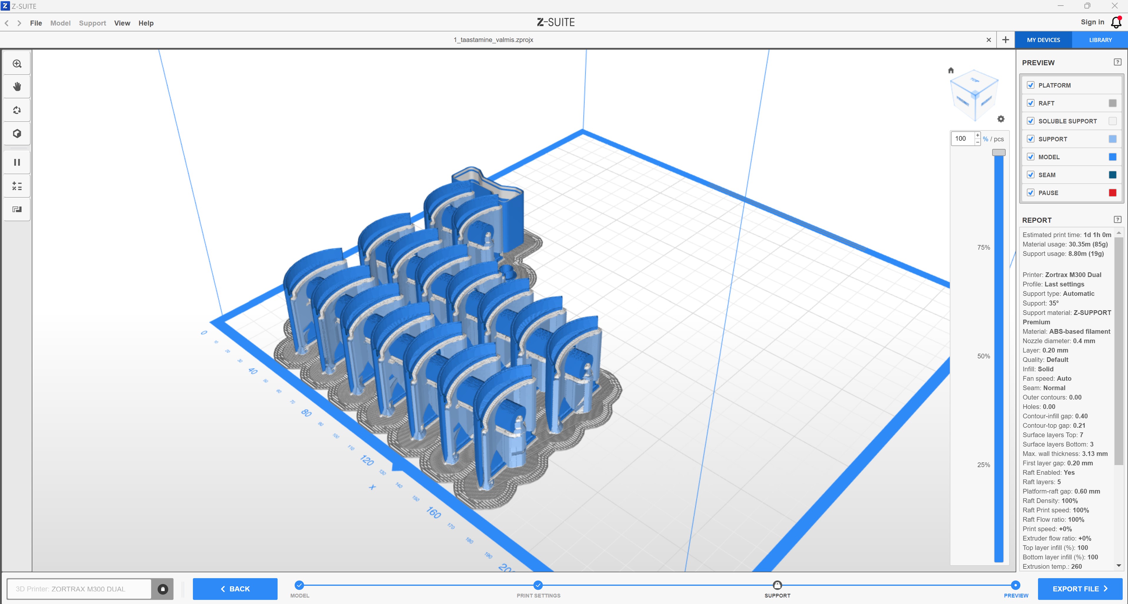
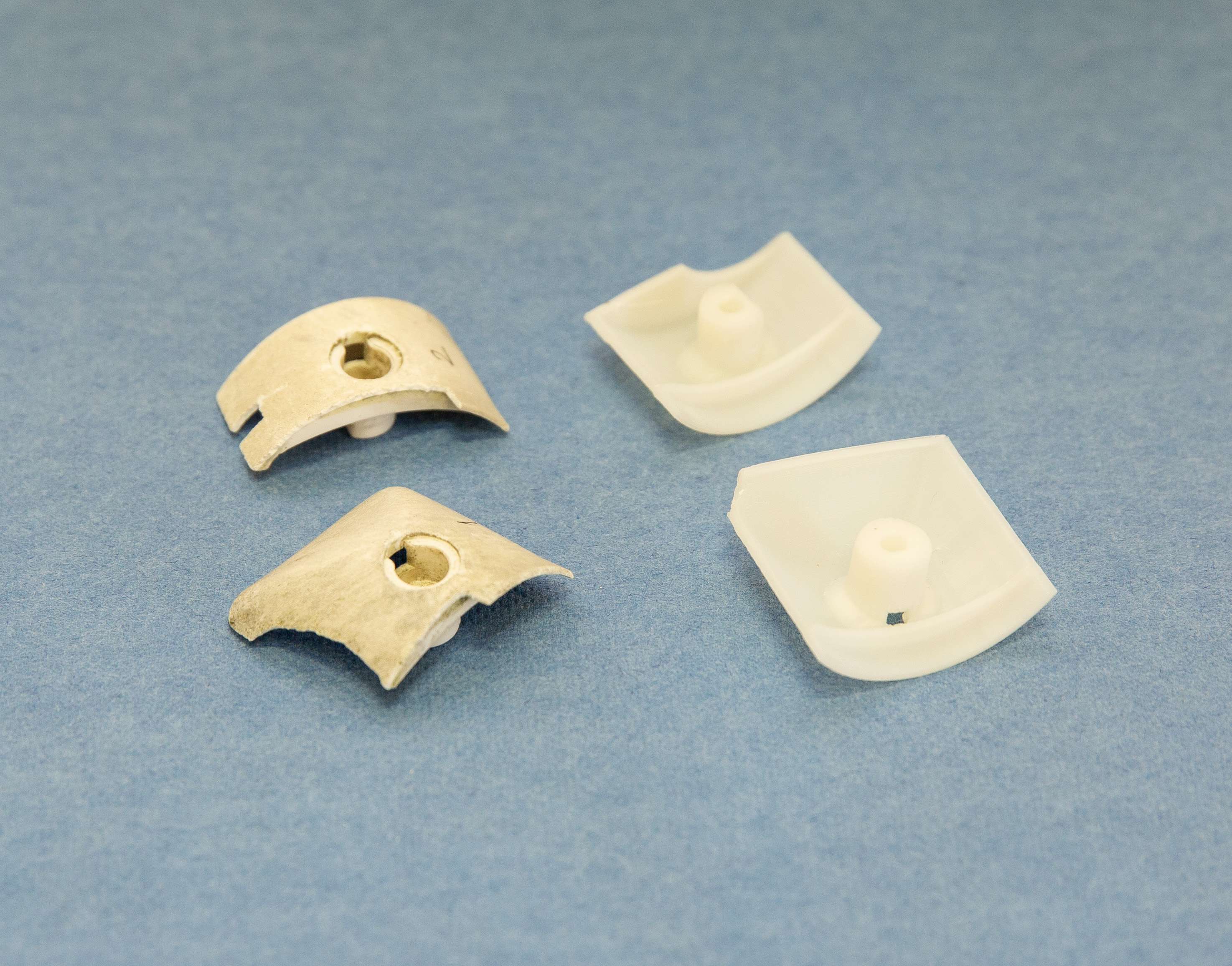
TSENTRISSE toodi plastikust detailid, millest oli vaja valmistada koopiad. Tauno Erik pani tööprotsessi täpsemalt kirja.
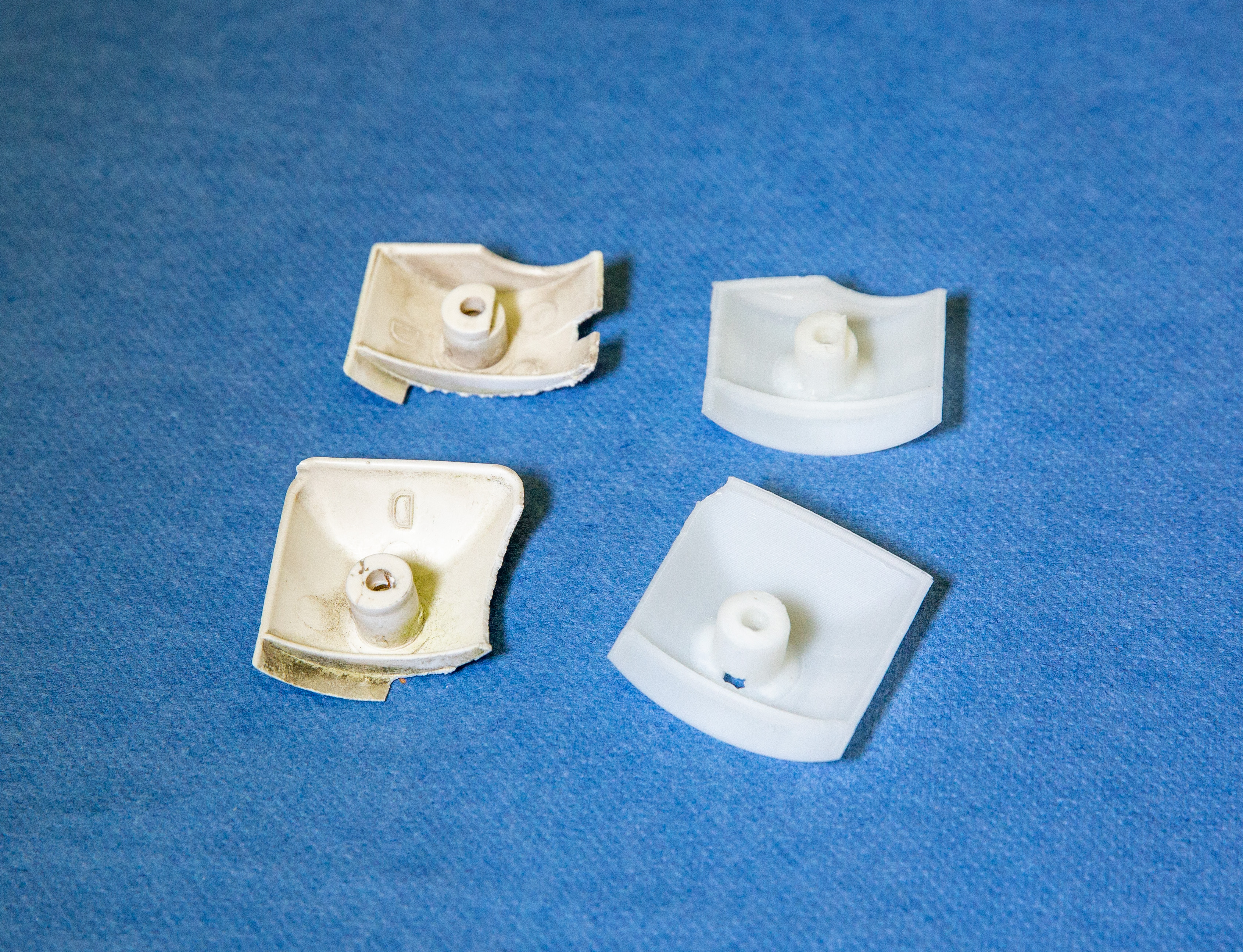
Tavaline protsess on selline, et kõigepealt on idee, siis tehakse sellest 3D mudel ja joonised, mille järgi valmistakse vajalik asi. Pöördprojekteerimine on vastupidine protsess: meil on asi olemas, aga oleks vaja seda taastoota, edasi arendada või mõnel muul põhjusel digitaliseerida.
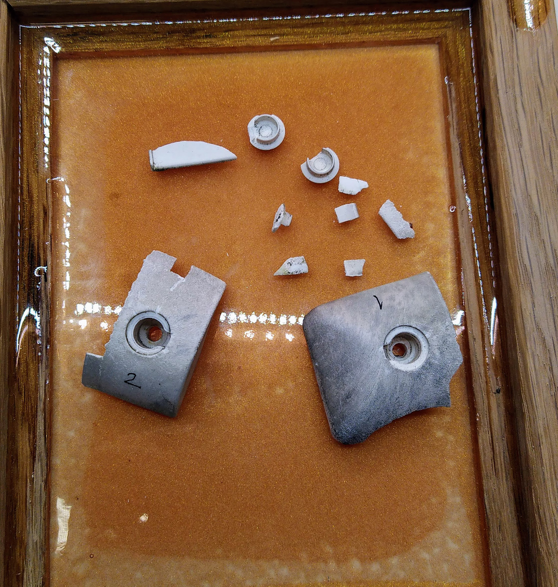
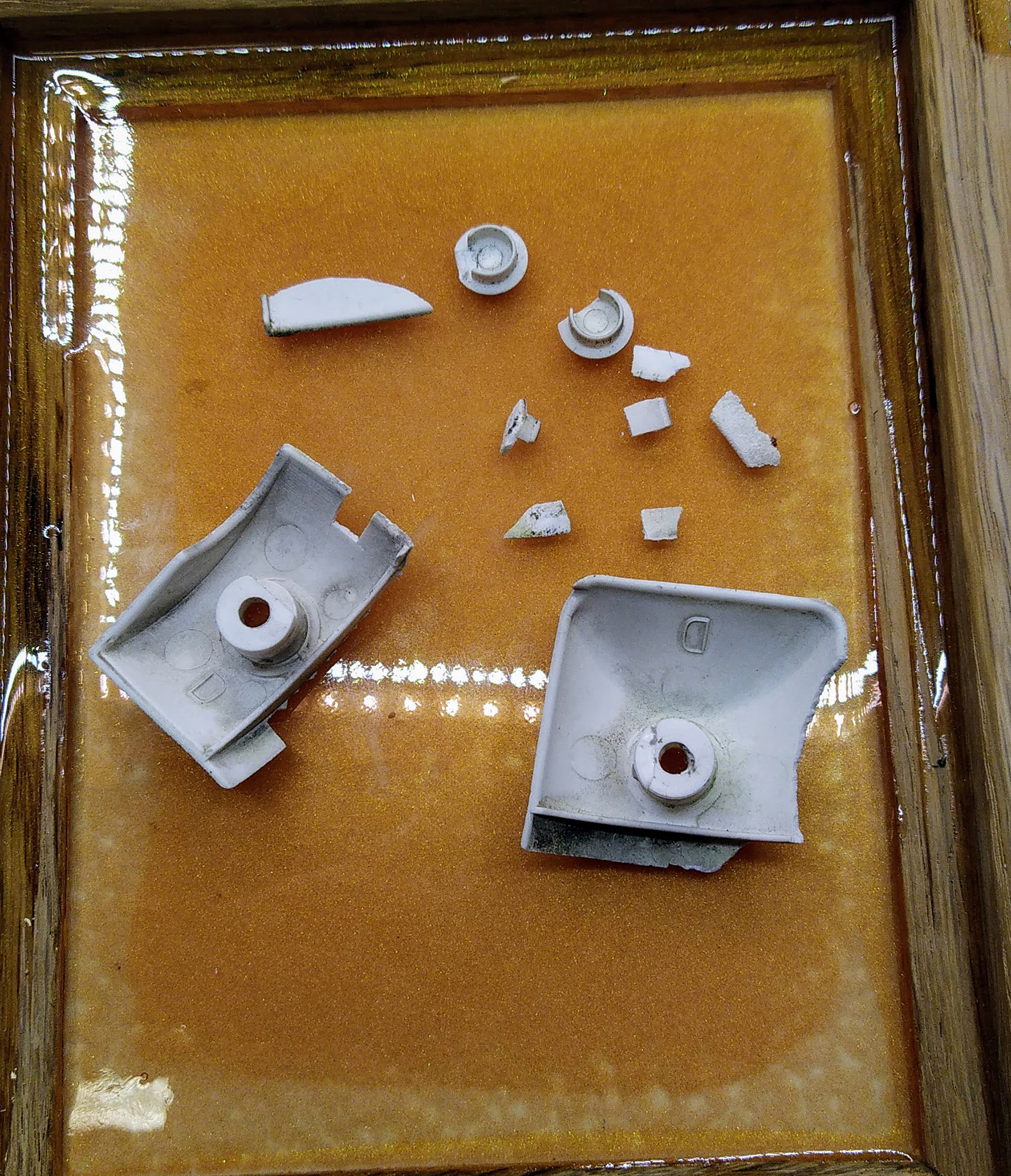
Antud juhul toodi taasloomisese pastikust detailid, mis olid päikse ja ilmastiku käes muutunud rabedaks ja hakkasid ära lagunema. Klient soovis 3D-printida asendusdetaile.
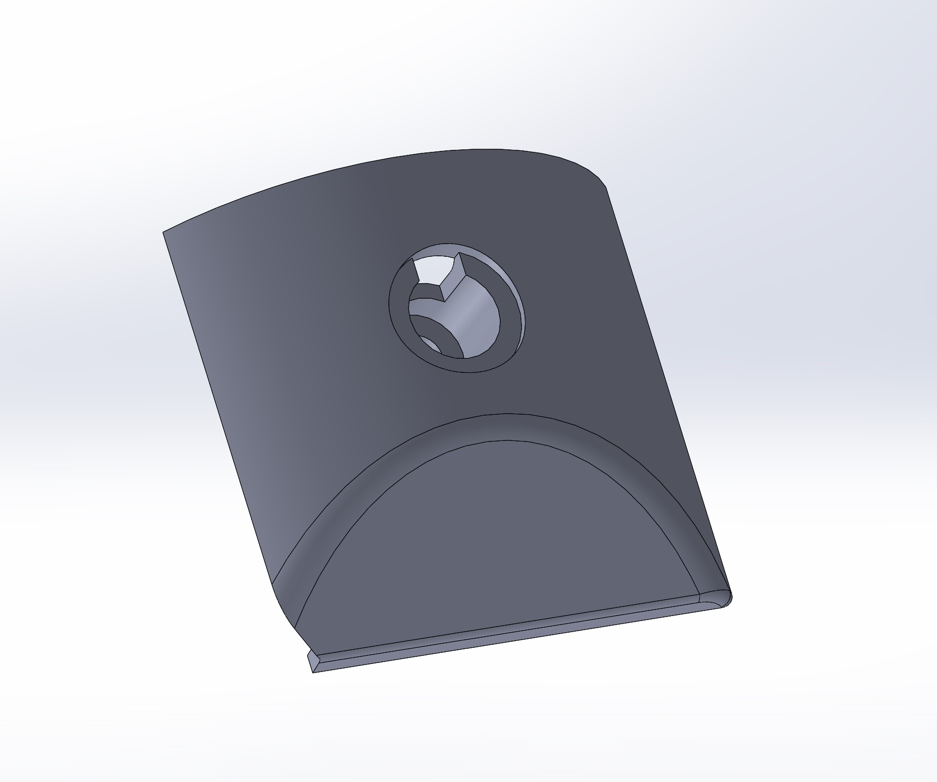
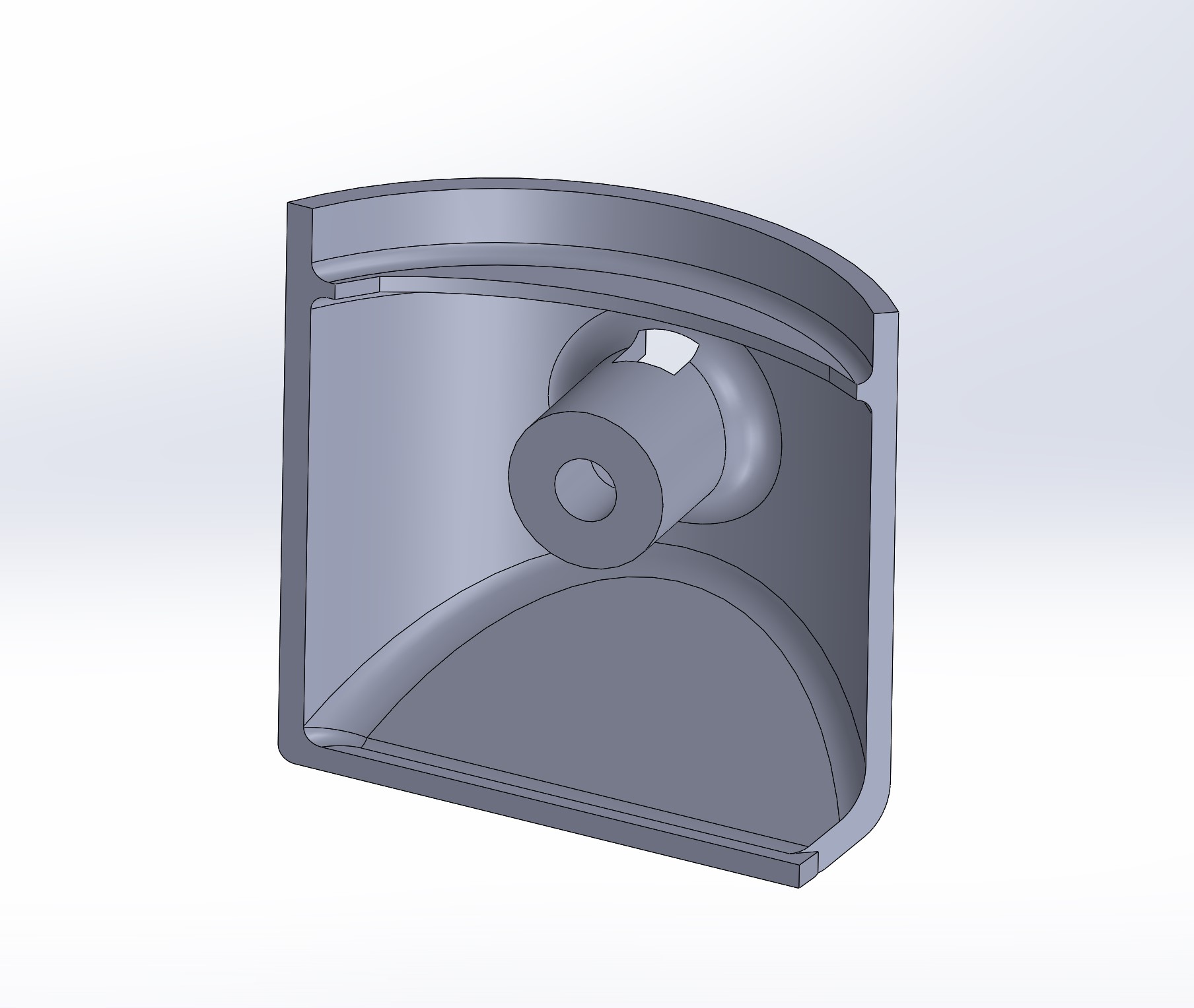
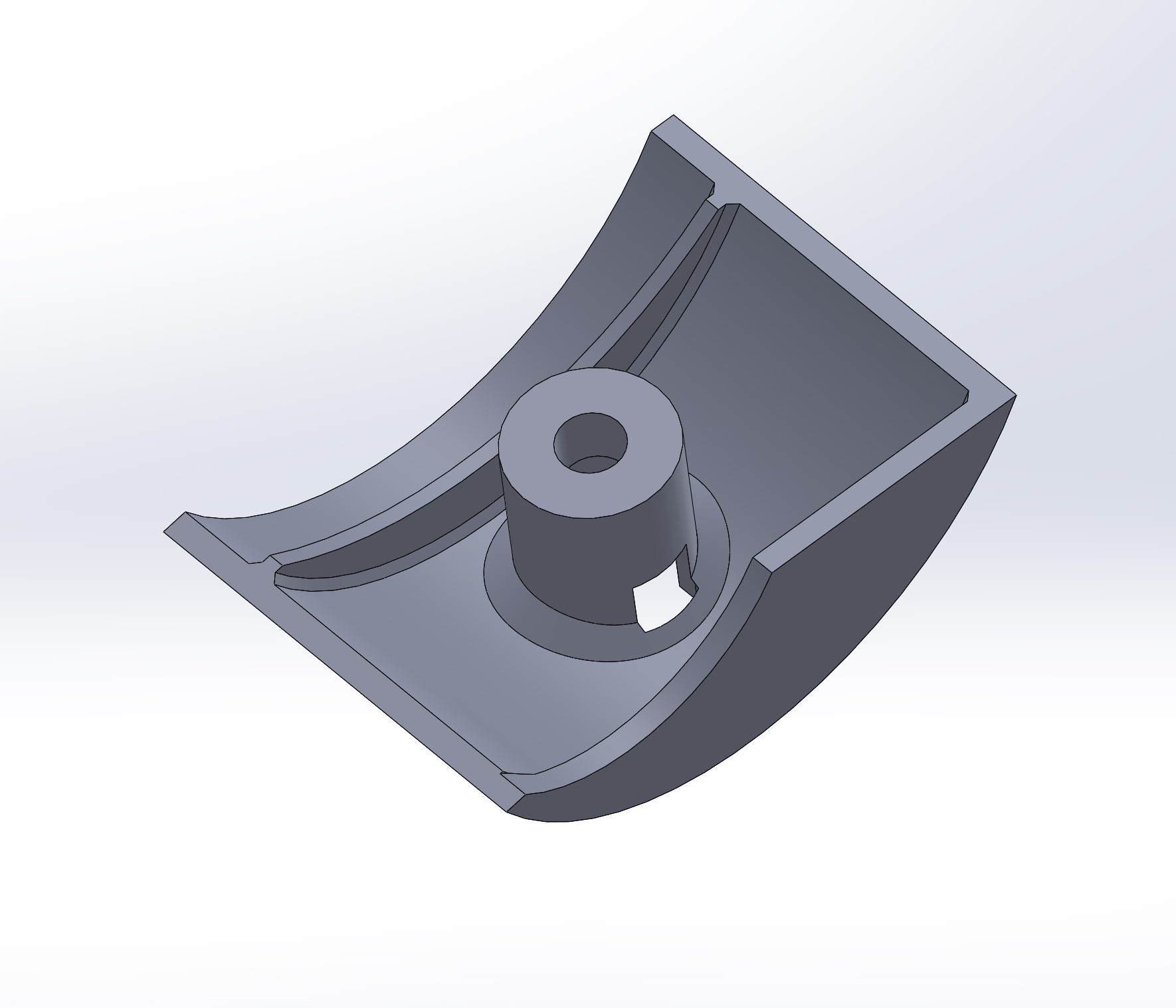
Selleks oli esmalt vaja luua 3D-mudel. Selleks oli mitu võimalust:
Kuna kliendi toodud detailid olid väga haprad ja kättevõtmisel tükkis neilt juppe küljest kukkuma, siis ma otsustain nad 3D-skanneerida. Vastasel juhul oleks tavalise möötmise käigus nad ära lagunenud ja ei oleks jäänud võimalust hiljem kontrollida, kui õige projekteeritud mudel on. Aga 3D-skanneerimise puhul jääb alles digitaalnekaksik .millega võrrelda.
Tööprotsess oli järgmine:
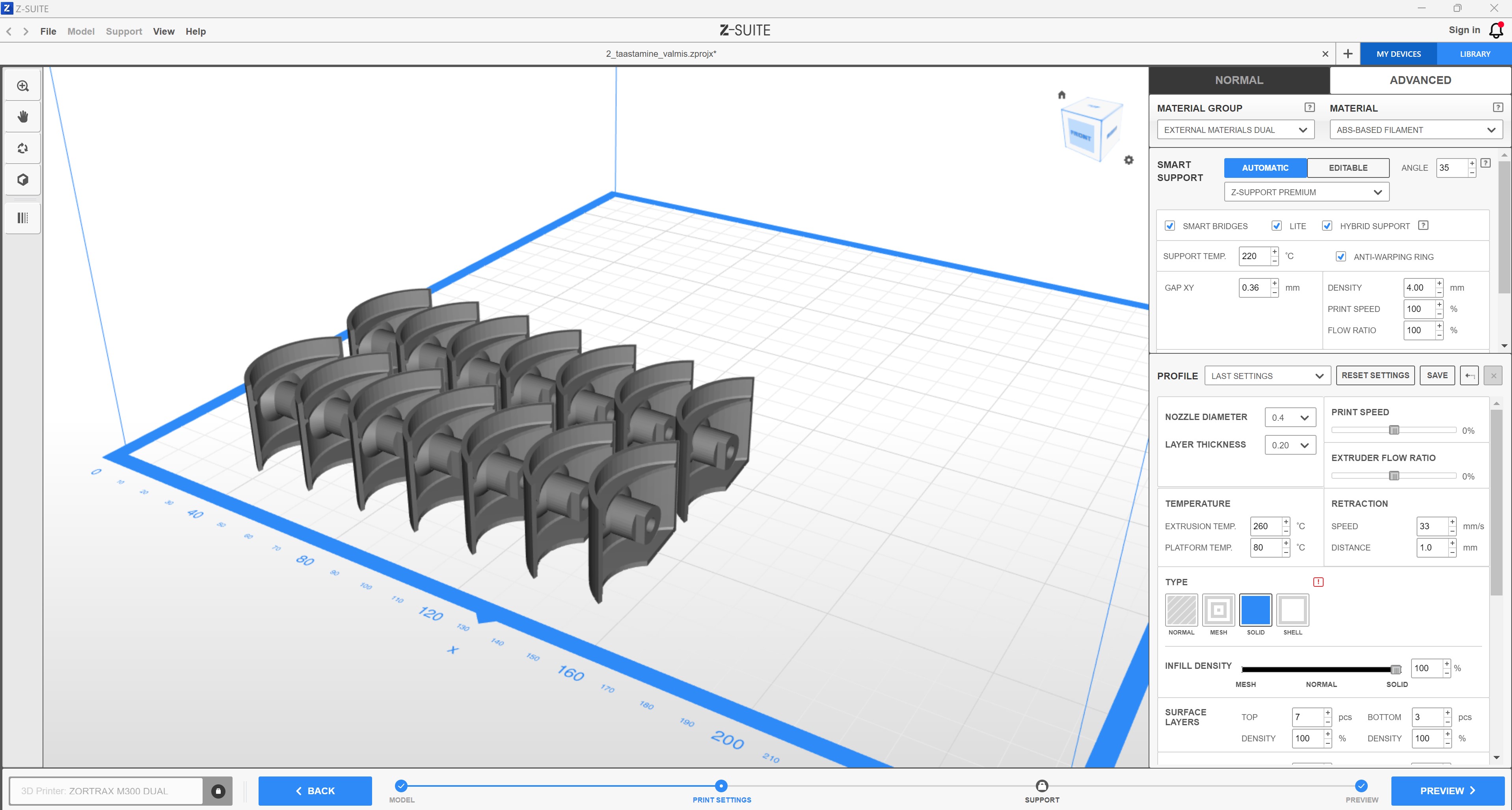
Enne 3D-printimist tasub mõelda, millist külge pidi panna objekt 3D-printerisse, kui palju on vaja tugimaterjali ja kuidas kihtide asetus mõjutab prinditud asja struktuurset tugevust. Kuna mul oli kasutada 3D-printer (Zortrax M300 Dual), kus on olemas eraldi vees lahustuv tugimaterjal, siis saaks teoreetiliselt printida ükskõik millist külge pidi.
Teostas ja pani kirja: Tauno Erik, tauno@tsenter.ee
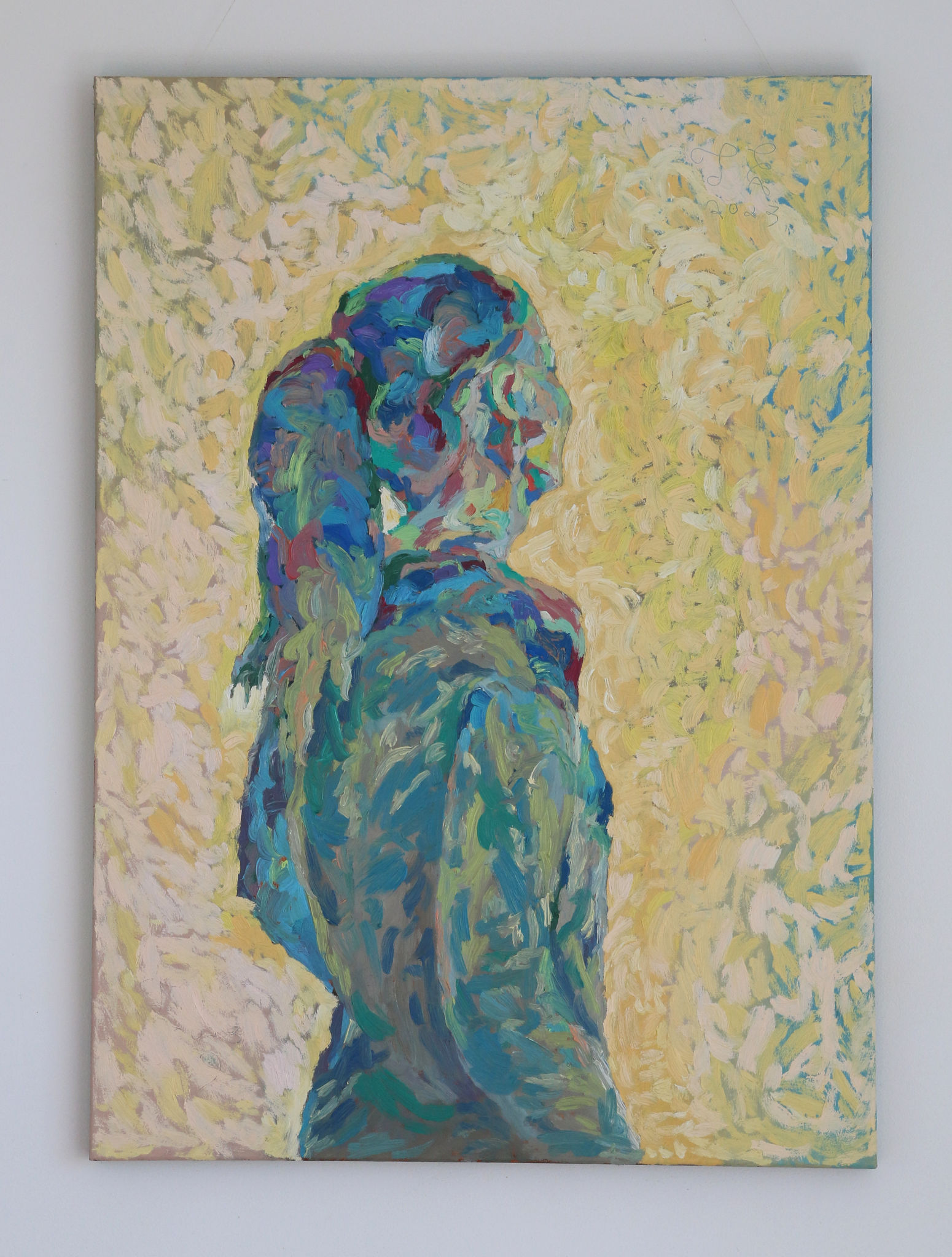
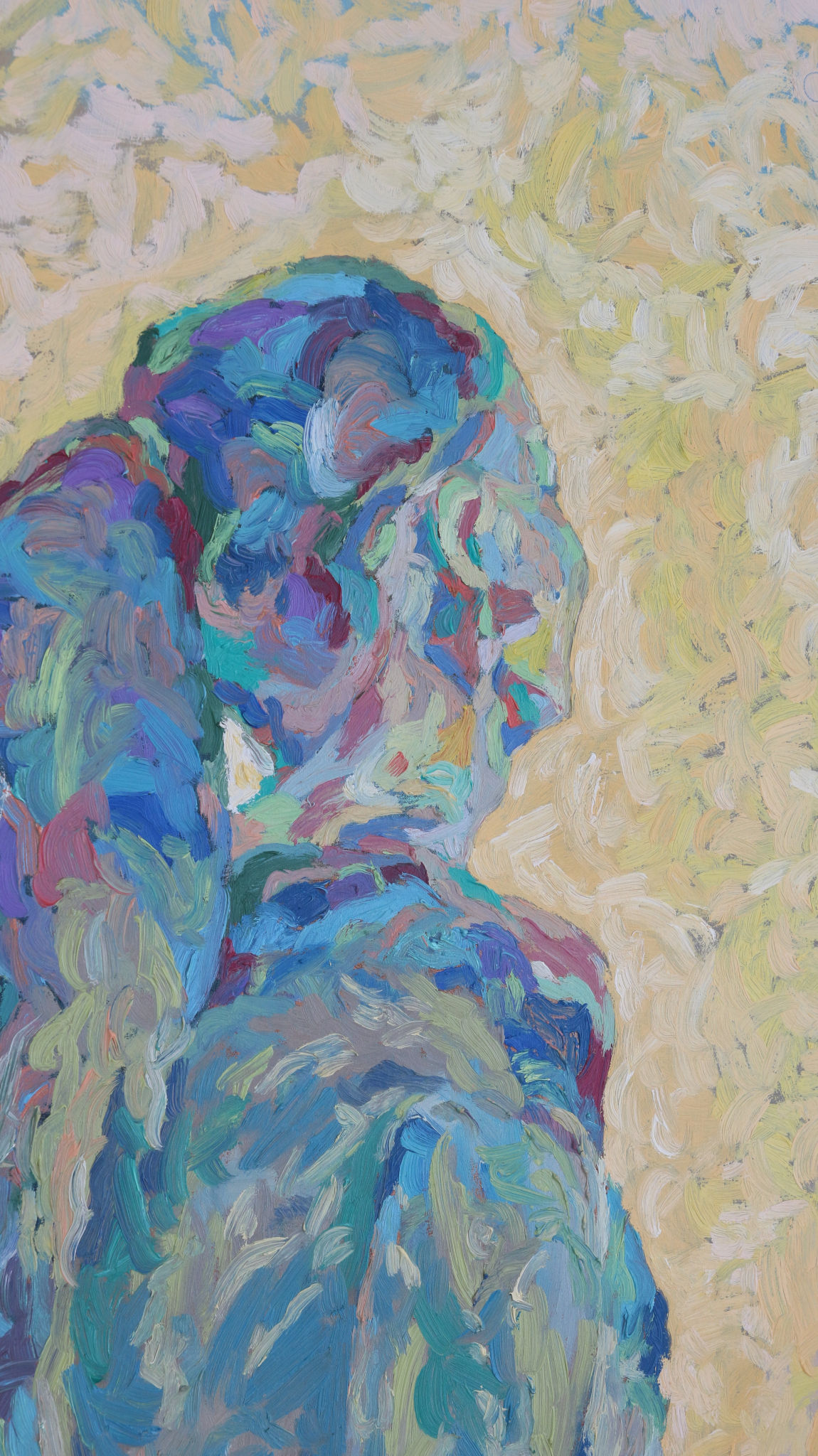
Oil on canvas, 60×80 cm
Algsed, originaal, detailid. Päikese ja ilma käes rabedaks muutunud ja deformeerunud kujuga.
3D skanneeritud detailid
Lihtsustatud geomeetriaga 3d skannid
CADis korrektsete mõõtudega taasloodud mudelid
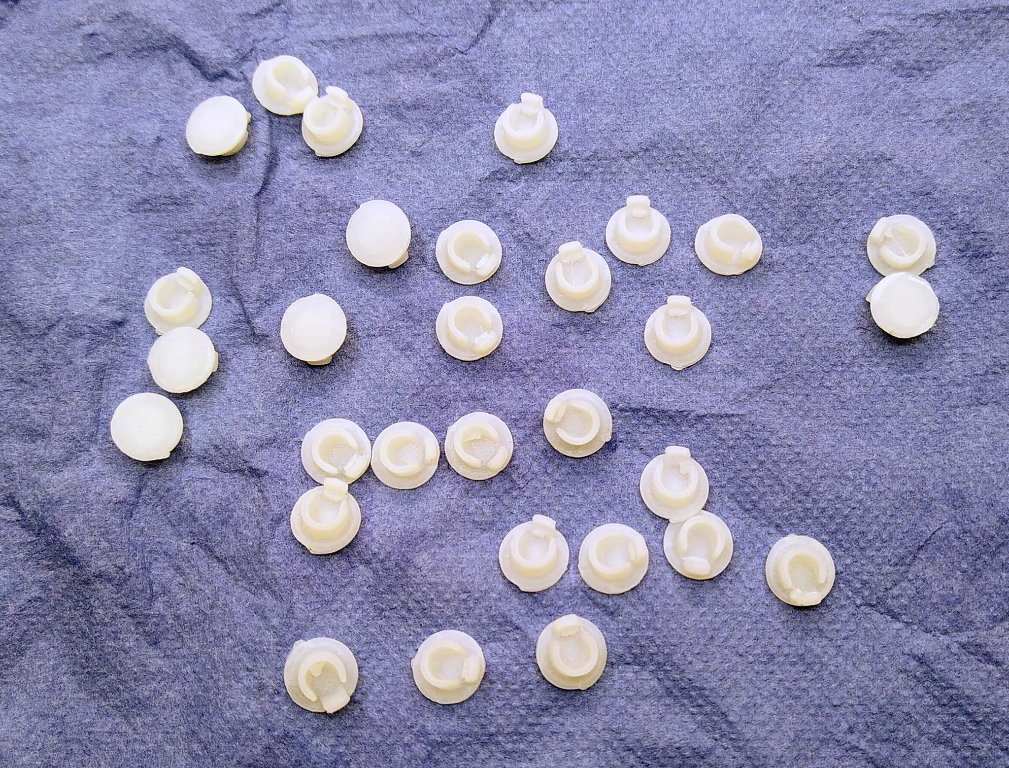
Valmis 3D-prinditud deatilid. Materjal ABS.
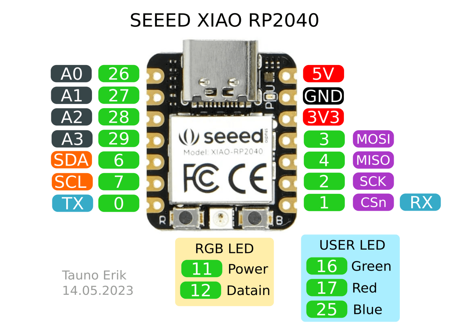
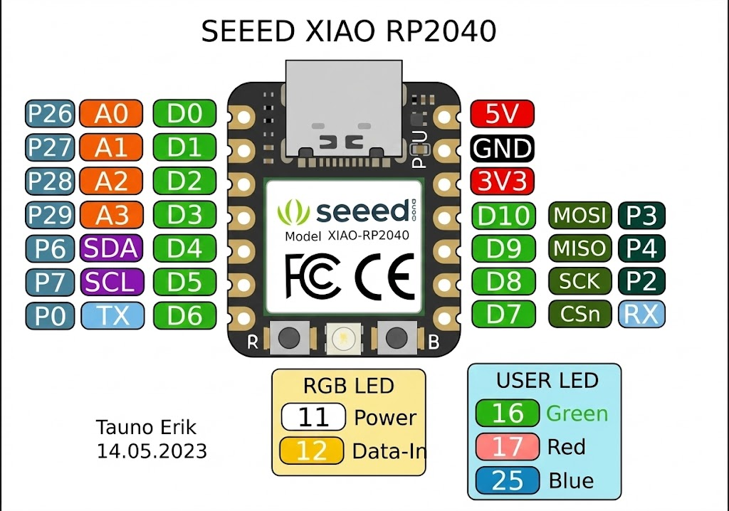
For some reason, PlatformIO hasn’t merged support for other RP2040 boards to its platform. So we have to do it manually.
PIO Home > Platforms > Advanced Installation and add:
https://github.com/maxgerhardt/platform-raspberrypi.git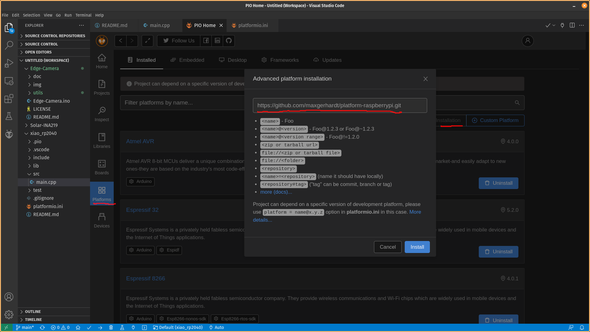
It has support for lots of RP2040-based boards. The full list is here.
For now (21.08.2023), the PlatformIO Project Wizard does not create XIAO RP2040 project files. and therefore we add platform info manually to the project.
Add platform info directly to the platformio.ini file. When you run it the first time it installs all the necessary files. It can take a lot of time.
[env:seeed_xiao_rp2040];
platform = https://github.com/maxgerhardt/platform-raspberrypi.git#develop
board = seeed_xiao_rp2040
framework = arduino
Updated version by Olivier Chatelain (30.12.2025):
#include <Arduino.h>
#include <Adafruit_NeoPixel.h>

const int pin_0 = 0;
const int pin_1 = 1;
const int pin_2 = 2;
const int pin_3 = 3;
const int pin_4 = 4;
const int pin_6 = 6;
const int pin_7 = 7;
const int pin_26 = 26;
const int pin_27 = 27;
const int pin_28 = 28;
const int pin_29 = 29;

const int user_led_green = 16;
const int user_led_red   = 17;
const int user_led_blue  = 25;

const int rgb_power_pin  = 11;
const int rgb_data_pin   = 12;

constexpr int num_of_pins = 16;
int all_pins[num_of_pins] = {
  pin_0,
  pin_1,
  pin_2,
  pin_3,
  pin_4,
  pin_6,
  pin_7,
  pin_26,
  pin_27,
  pin_28,
  pin_29,
  user_led_green,
  user_led_red,
  user_led_blue,
  rgb_power_pin,
  rgb_data_pin
};

constexpr int NUM_RGB_COLORS = 5;
int rgb_colors[NUM_RGB_COLORS][3] = {
  {254,10,10},
  {10,254,10},
  {10,10,254},
  {254,254,10},
  {10,254,254}
};

// https://learn.microsoft.com/en-us/cpp/cpp/constexpr-cpp?view=msvc-170&viewFallbackFrom=vs-2019
constexpr int RGB_PIXELS = 1;

constexpr int DELAY_TIME = 500;

Adafruit_NeoPixel pixels(RGB_PIXELS, rgb_data_pin, NEO_GRB + NEO_KHZ800);

void setup() {
  Serial.begin(115200);

  for (int i = 0; i < num_of_pins; i++){
    pinMode(all_pins[i], OUTPUT);
  }

  digitalWrite(rgb_power_pin, HIGH); // RGB Power ON

  pixels.begin();
}

void loop() {

  // Pins test
  for (size_t i = 0; i < (num_of_pins-2); i++){
    digitalWrite(all_pins[i], HIGH);
    delay(DELAY_TIME);
    digitalWrite(all_pins[i], LOW);
    delay(DELAY_TIME);
  }

  // RGB LED test
  for (size_t i = 0; i < NUM_RGB_COLORS; i++){
    pixels.clear();
    pixels.setPixelColor(0, pixels.Color(rgb_colors[i][0], rgb_colors[i][1], rgb_colors[i][2]));
    pixels.show();
    delay(DELAY_TIME);
  }
  pixels.clear();
  pixels.setPixelColor(0, pixels.Color(0,0,0));
  pixels.show();
}
60*90 cm, oil on canvas

50*70 cm, oil on canvas
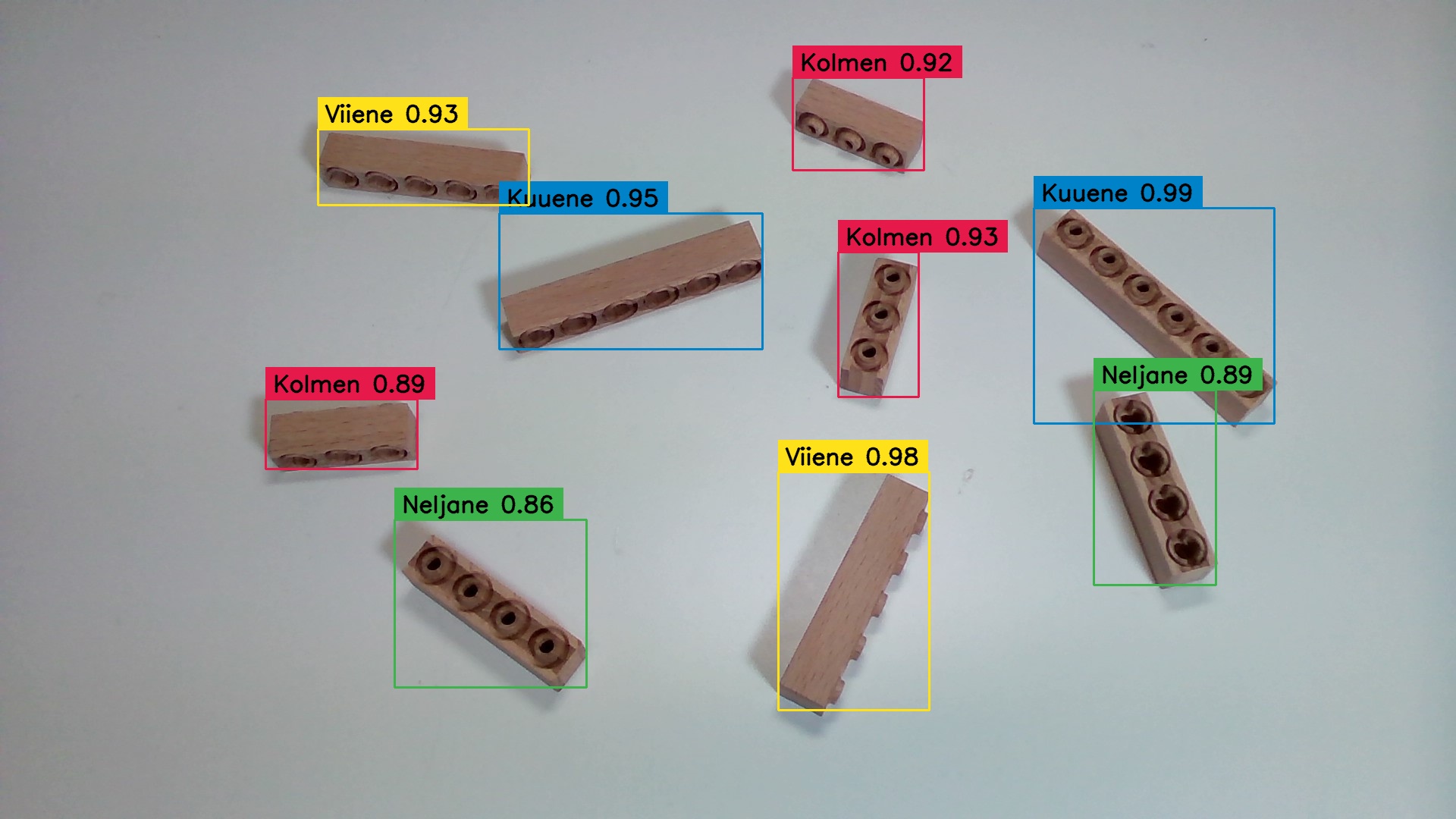
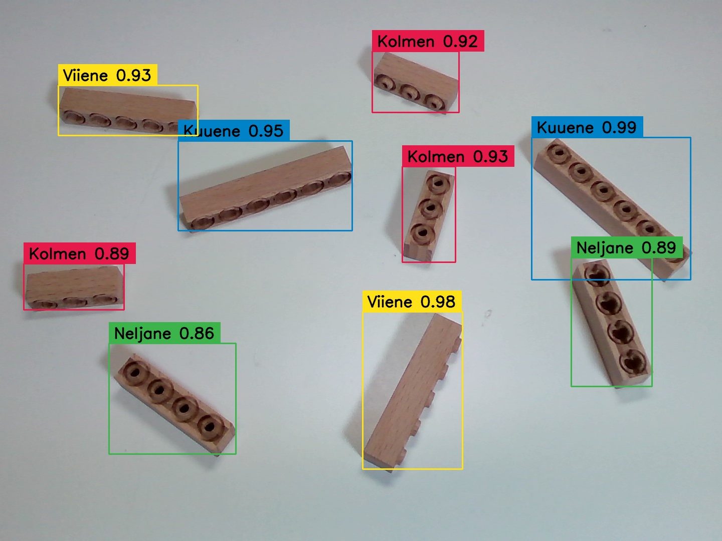
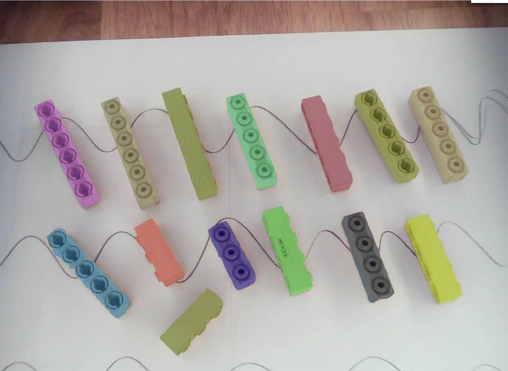
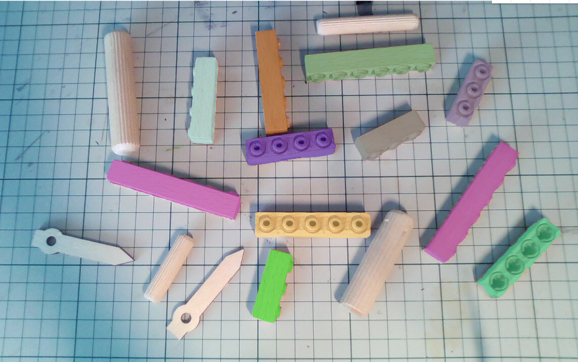
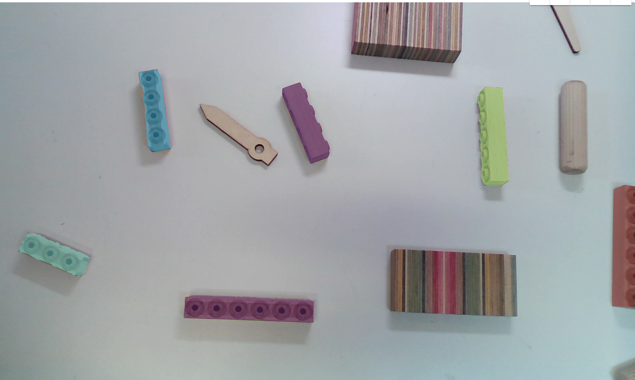
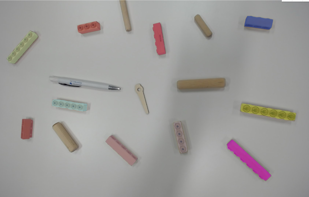
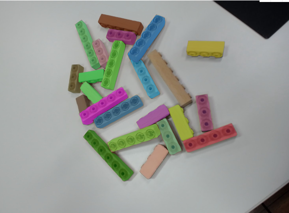
My first goal was to test whether can I make machine vision projects that identify different sizes of these wooden bricks from Woodi. I had four different sizes of bricks.
First I made a bunch of images separately of each brick on a different angle. Then many of them together. I used my two webcams and cell phones. After some testing, I started to add some similar sizes wooden objects to images so the model will separate the bricks from other stuff.
It would be good to use real situation pictures were it would be used. Same kind of camera, lighting and background.
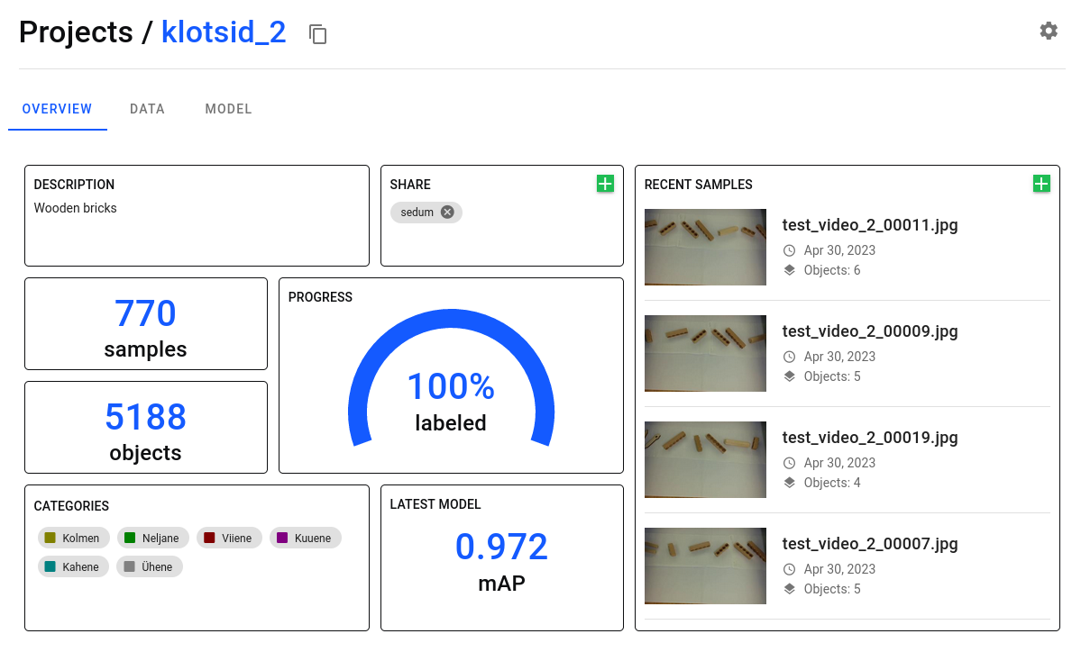
I used trainyolo.com to label all the images. I Collected 770 images and labelled 5188 objects together. And trained 8 models until I was finally satisfied with the results.
My Colab to train the model. Almost the same as the example from trainYOLO.
And my Python code on GitHub
I used Yolo version 8.
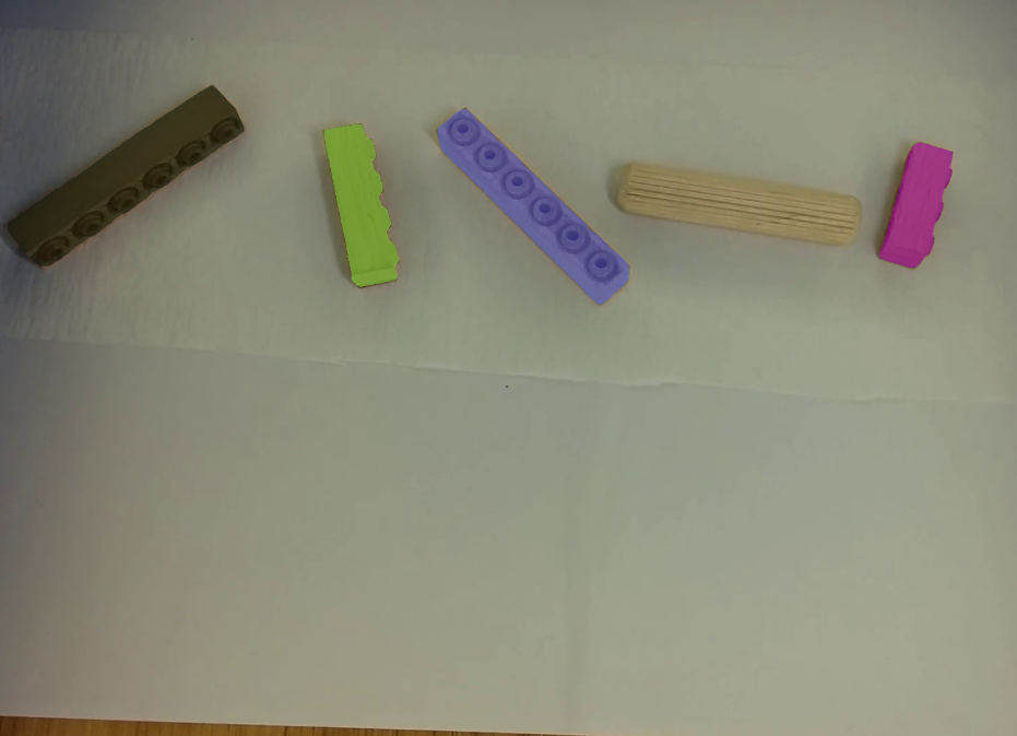
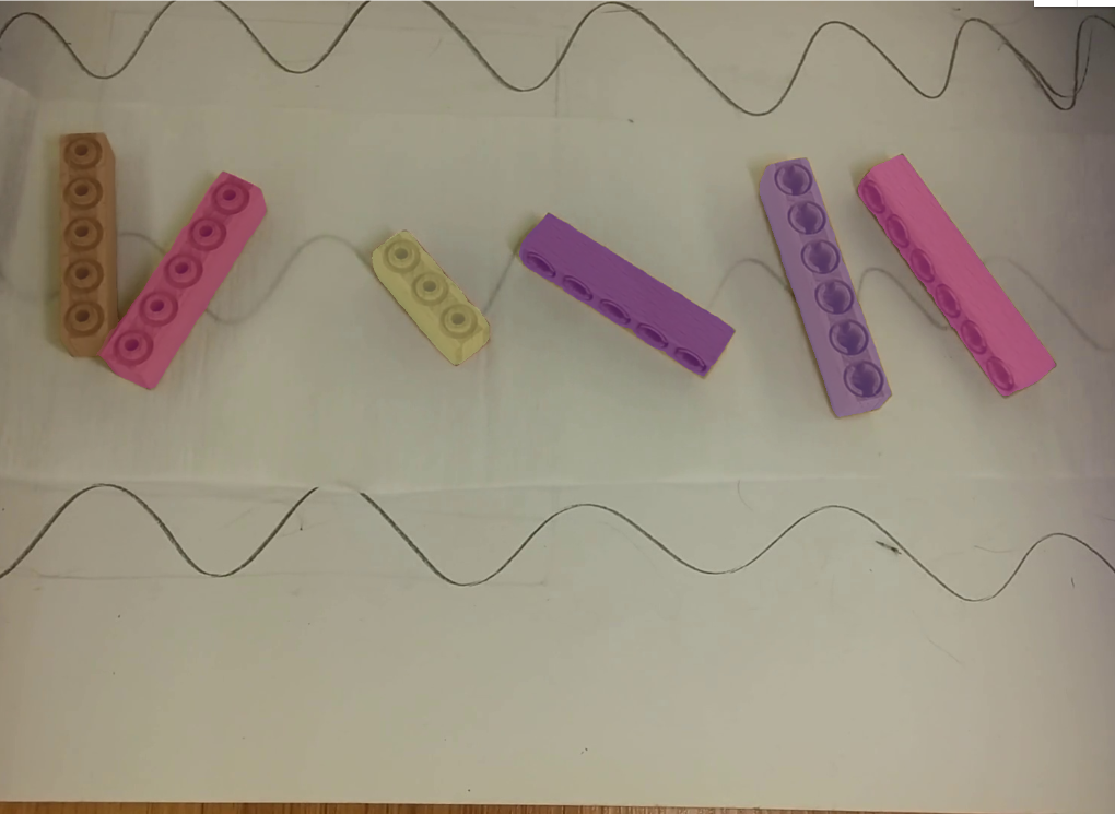
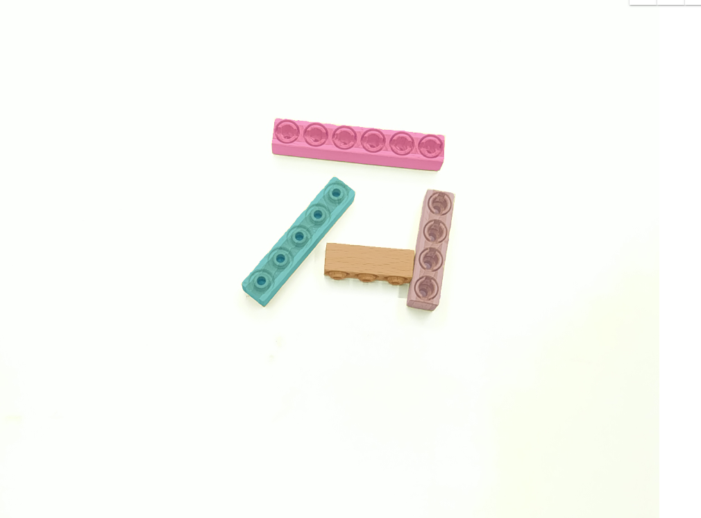
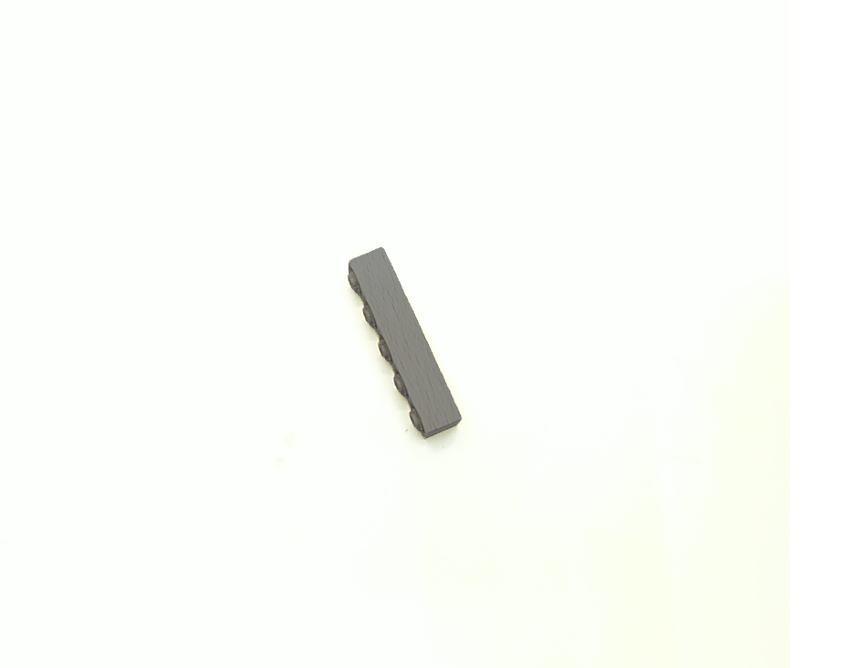
Sample images from the dataset. Segmented.
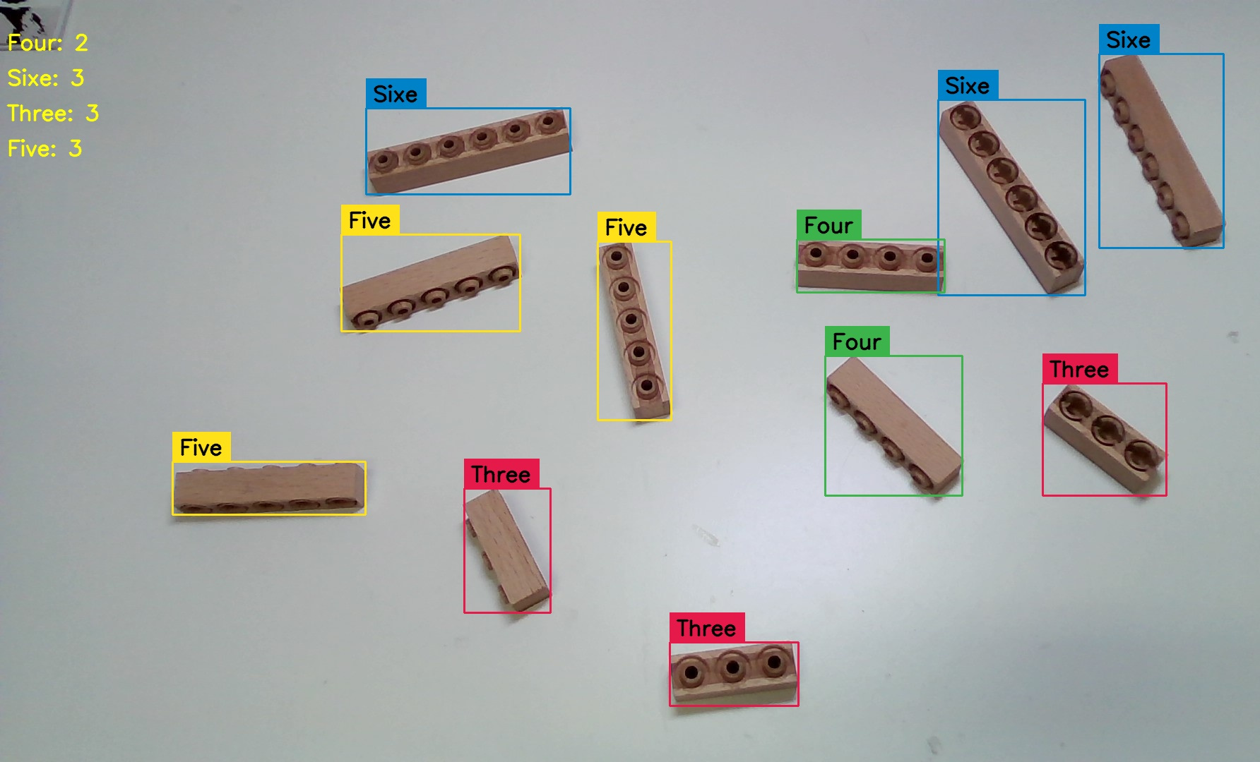
In this example, it detects all four sizes of brick, tracks them and counts them when they cross the green line.
Detects objects only in the predefined zone (drawn box).
pip install virtualenv
python3 --version
python3.10 -m venv env
source env/bin/activate
pip list

~ deactivate
Save and instal requirements
pip freeze > requirements.txt
~ pip install -r requirements.txt
nvidia-smi
kill -KILL PID_number
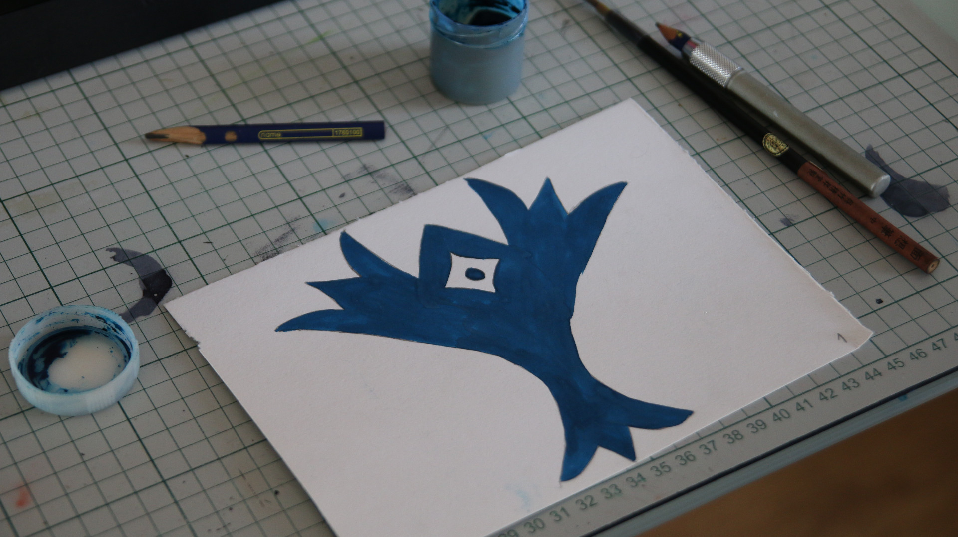
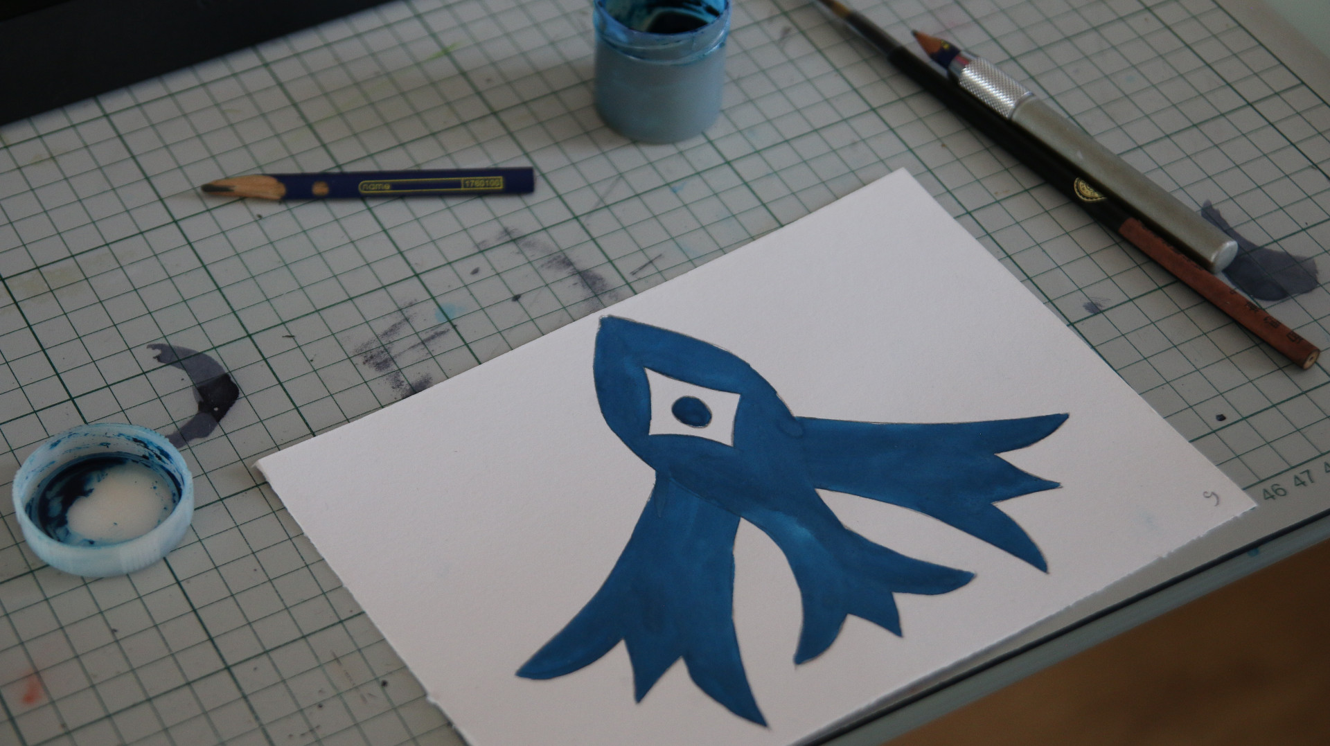
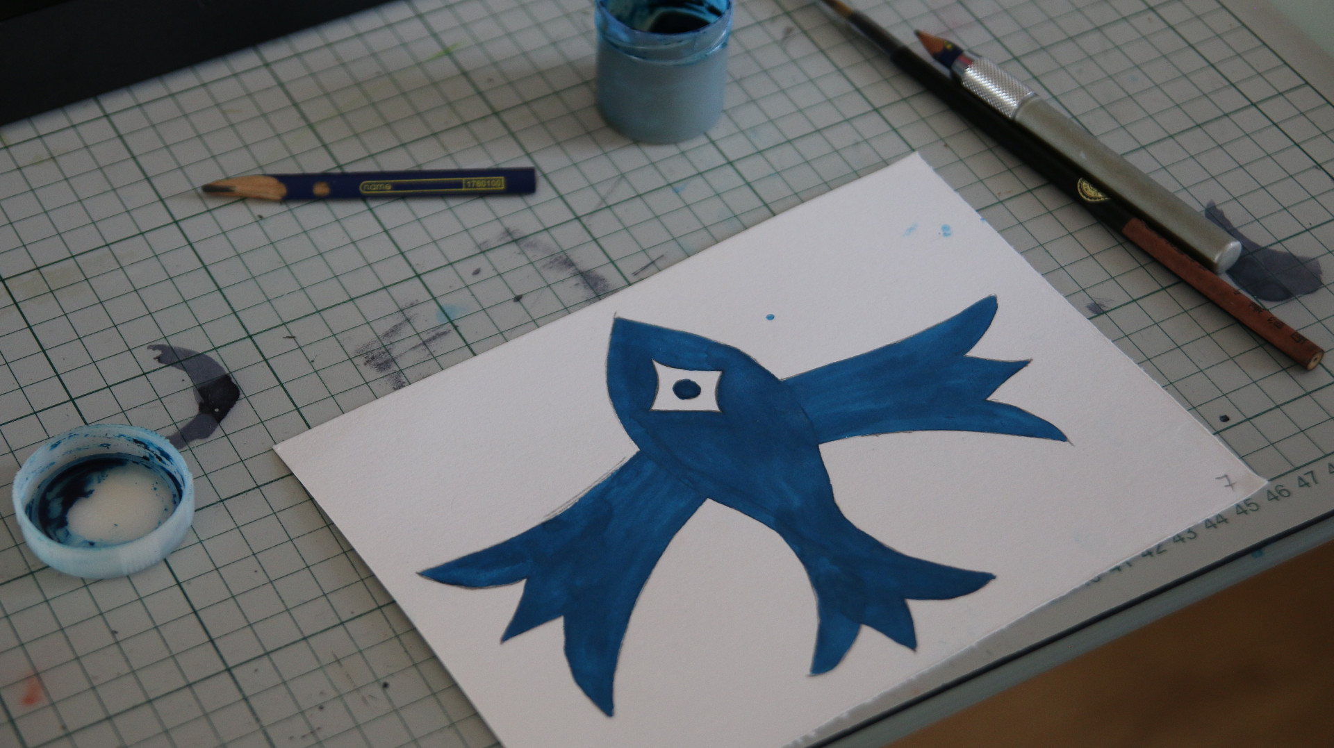
Stop-motion animation, Gouache paintings.
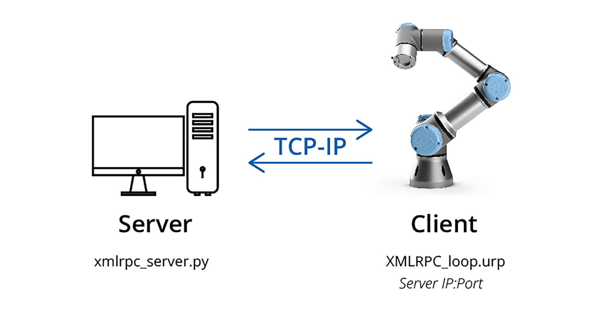
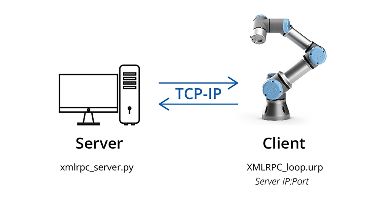
This is my demo code on how to use the XML-RPC to communicate with Universal Robots (UR). UR is the client and PC is the server that runs the Python script. On the demo code, the script only changes the x coordinate.
Enable remote control on the robot side.
You must change the server IP address and port in the UR code. Execute the server first then UR.
Pose format: Pose = [x, y, z, rx, ry, rz]
XML-RPC is a remote procedure call (RPC) protocol which uses XML to encode its calls and HTTP as a transport mechanism.
My example code on my GitHub: github.com/taunoe/UR-scripts