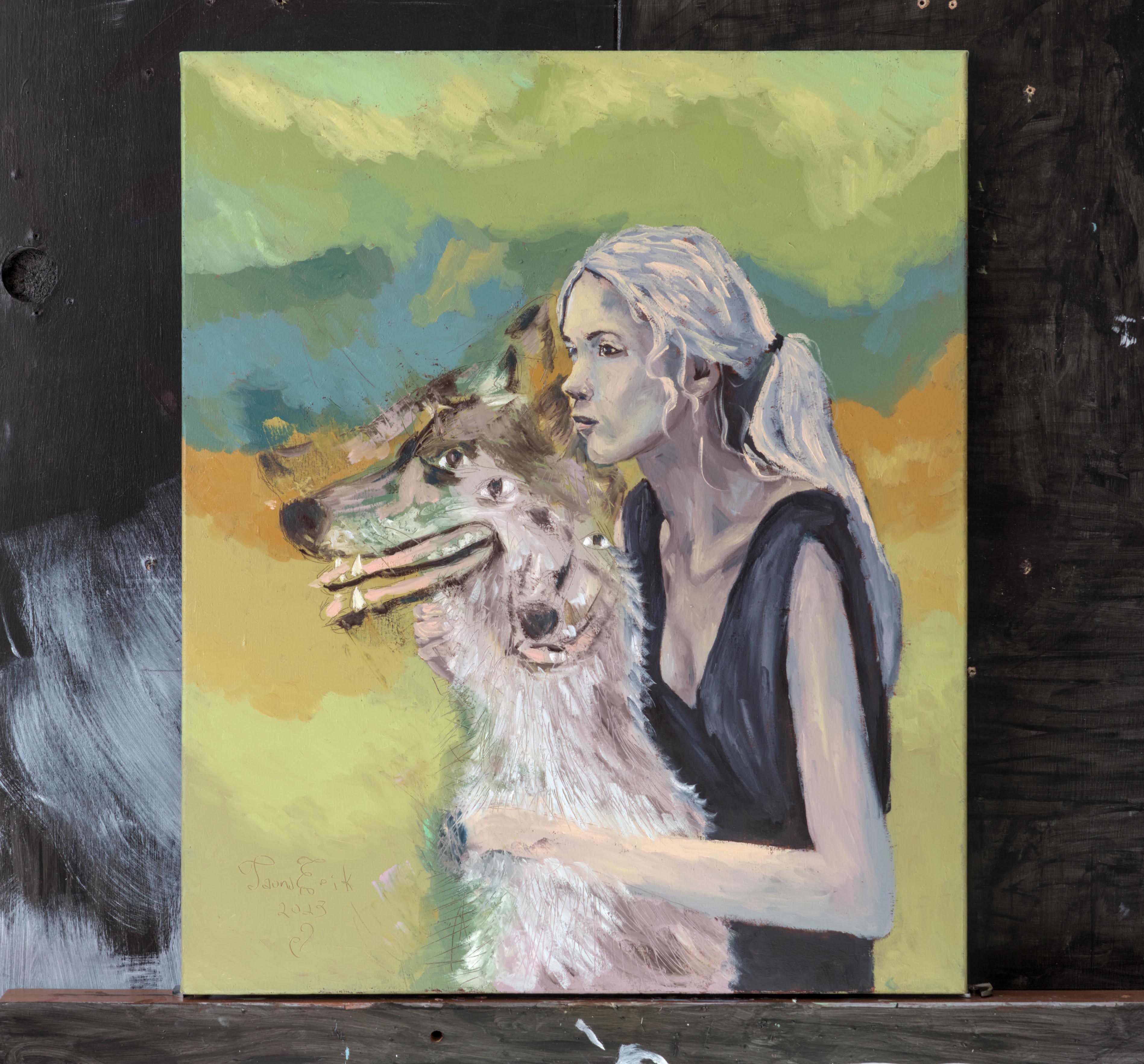
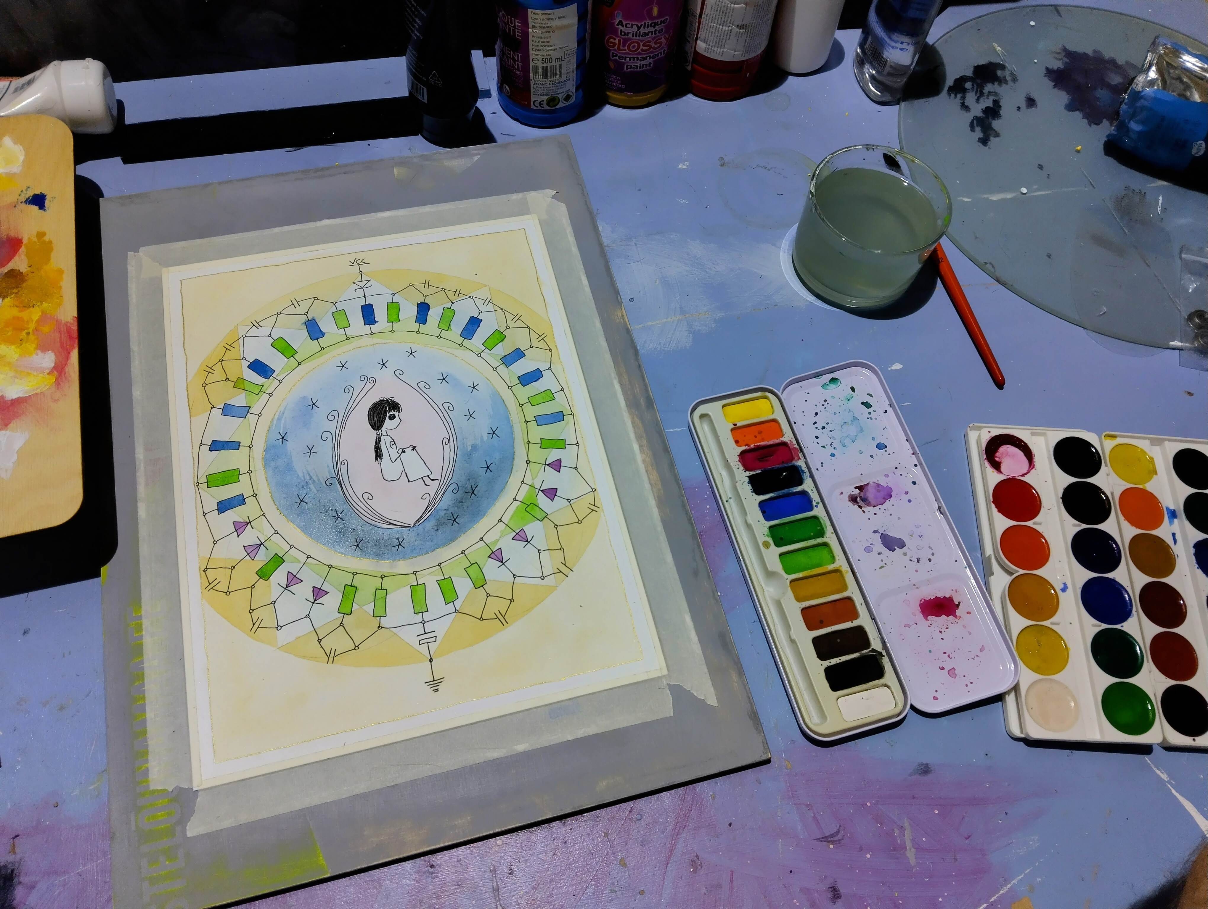
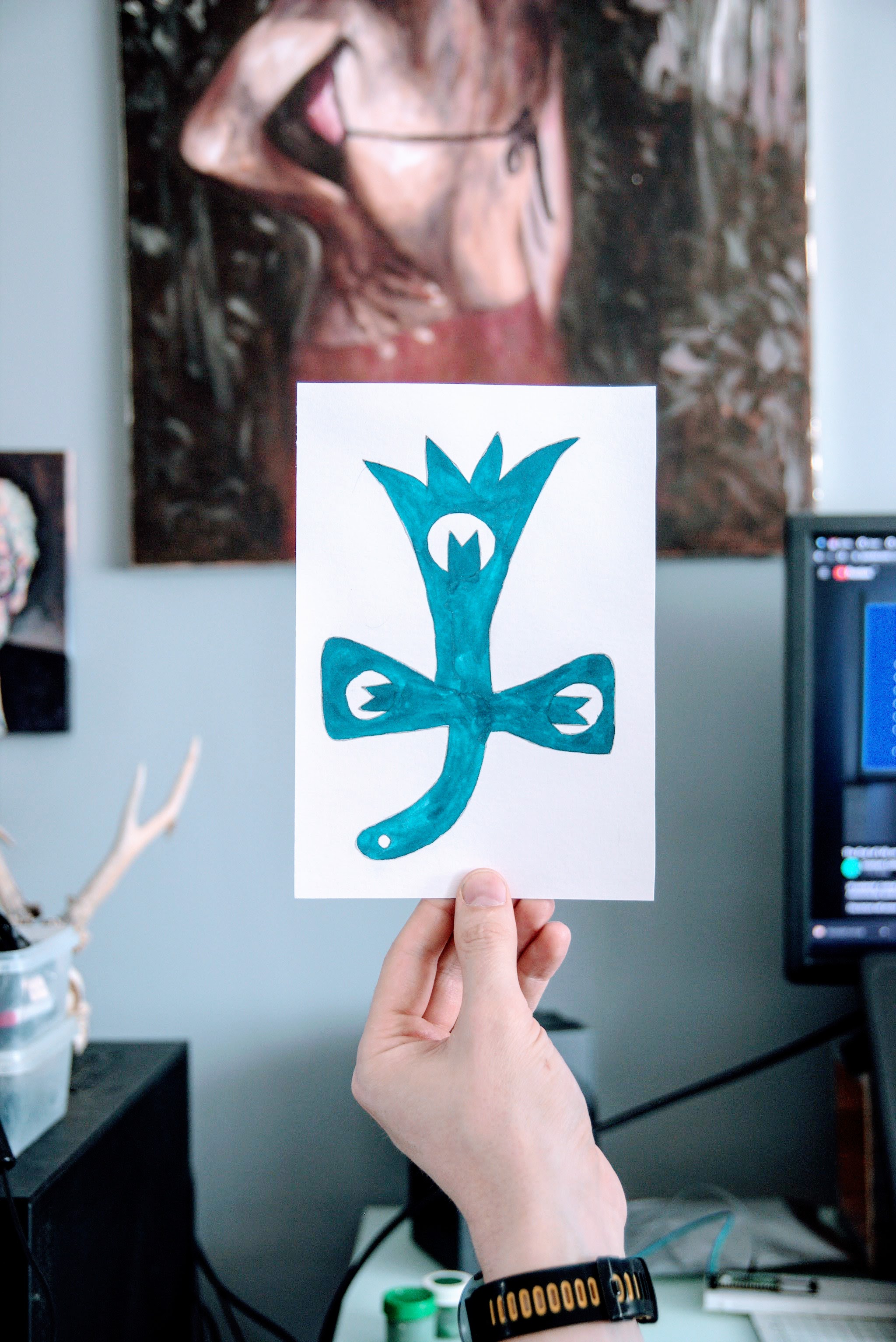
Meeled, Tauno Erik, 2023, 24*32 cm
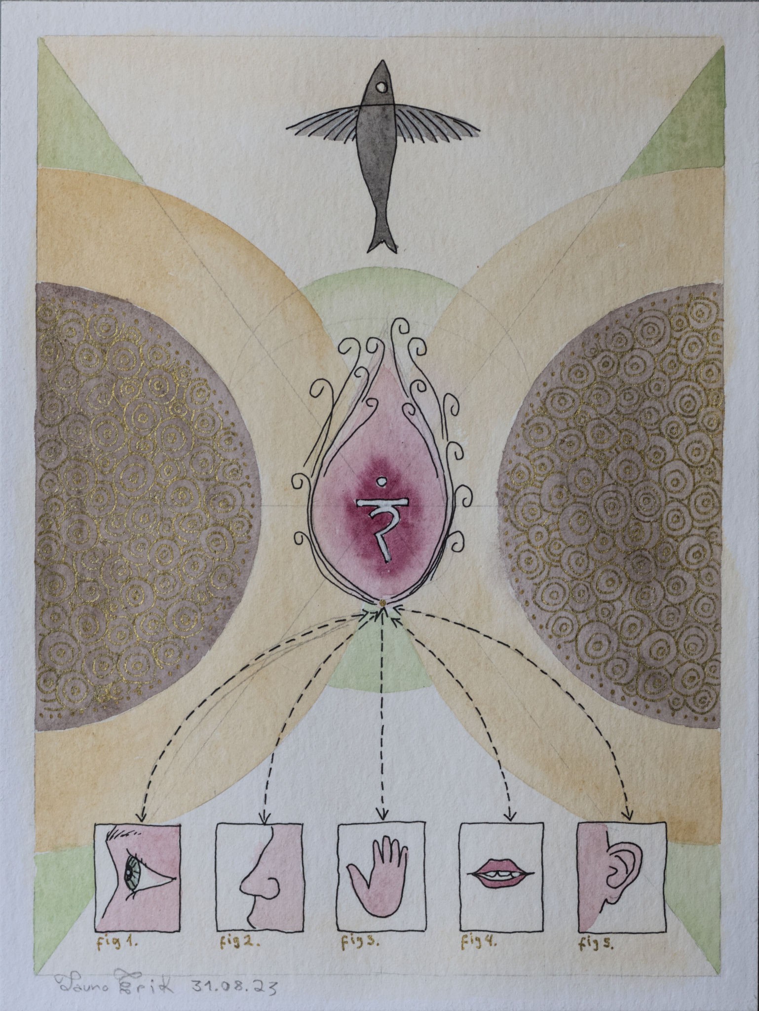

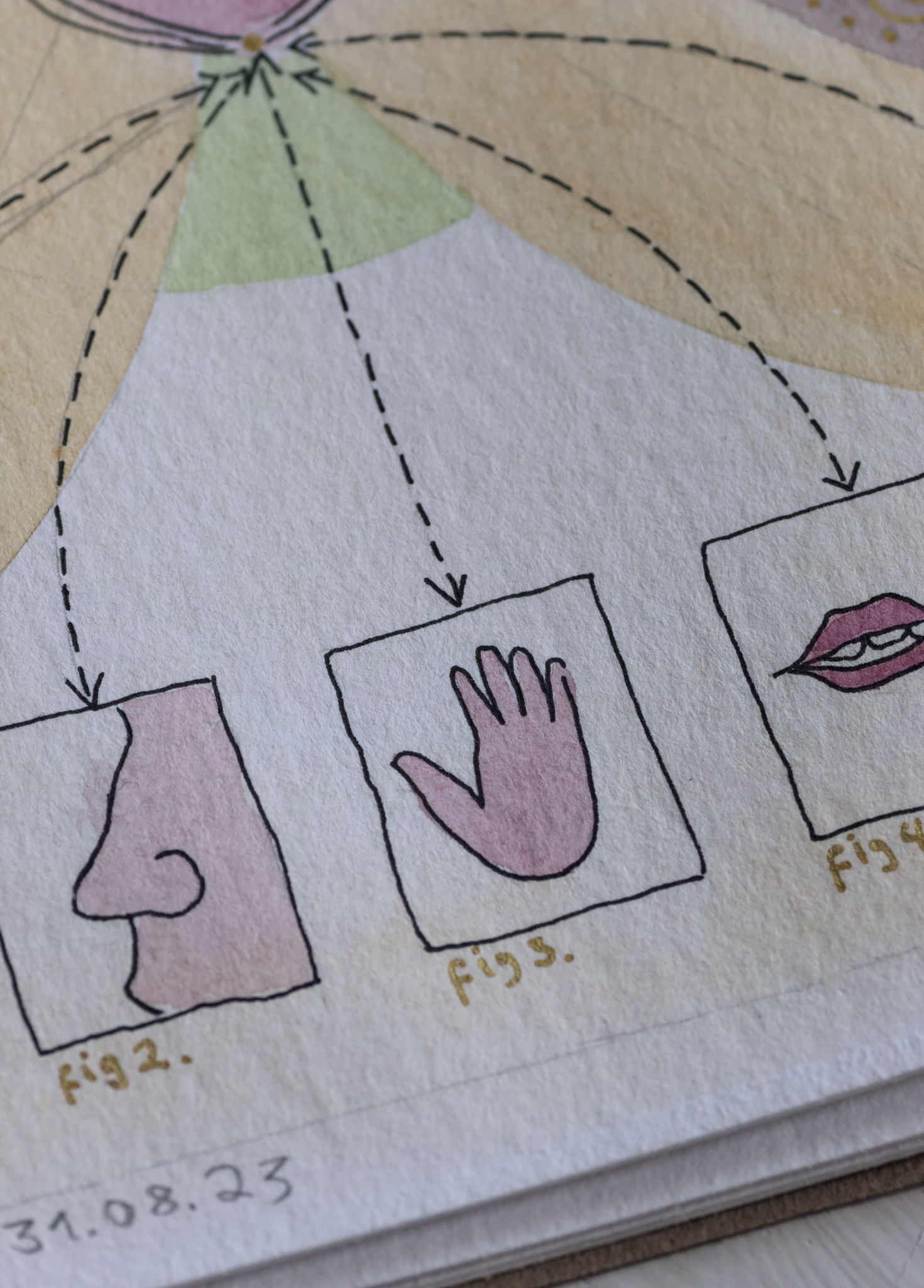
Meeled, Tauno Erik, 2023, 24*32 cm
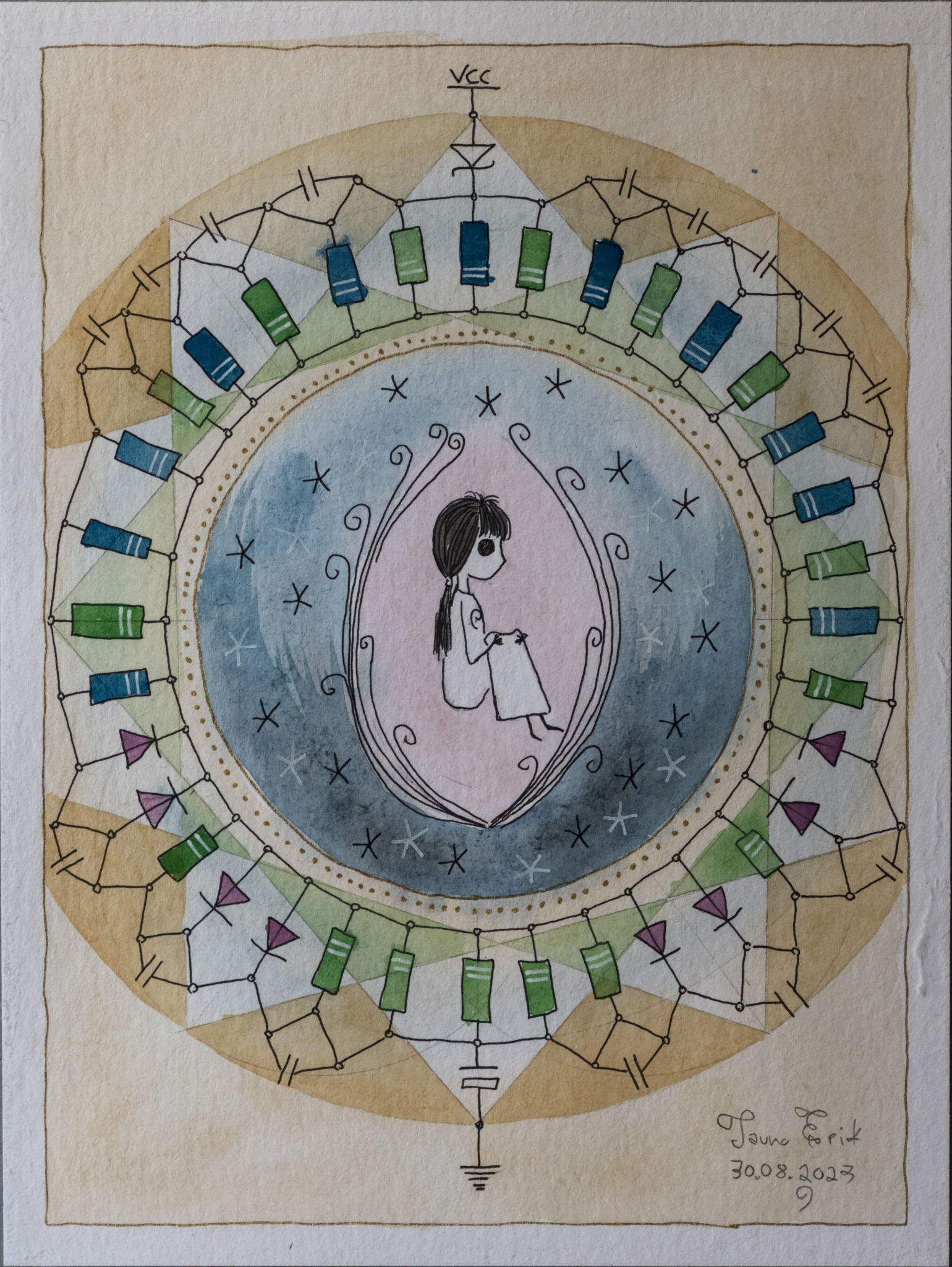
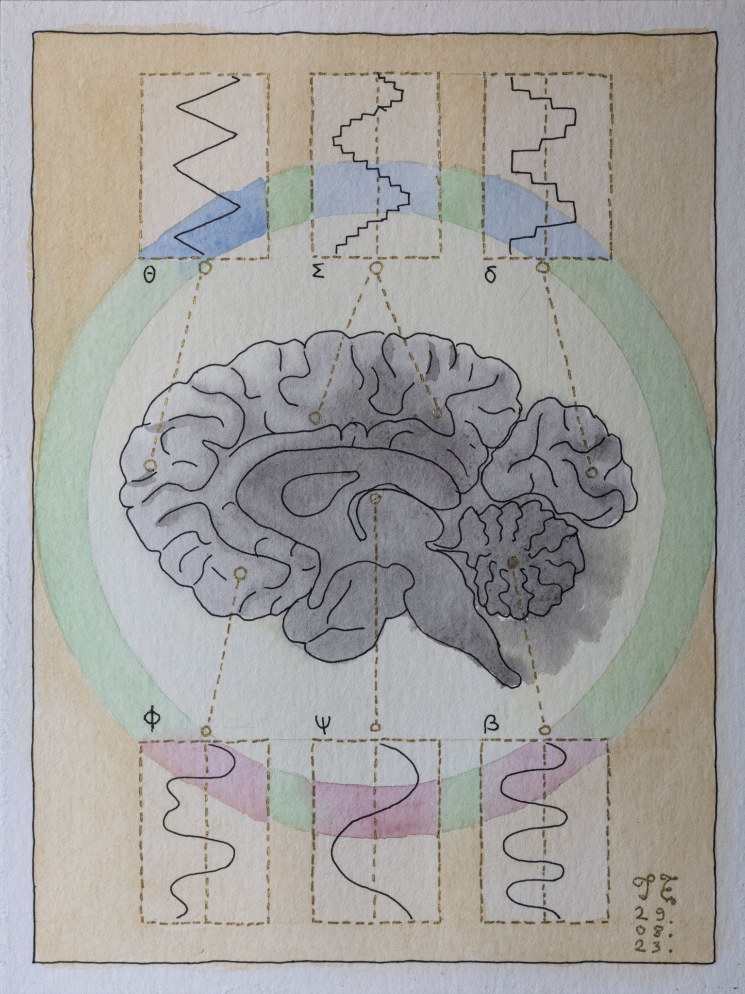
Isolatsioonis, Tauno Erik, 2023, 24*32 cm


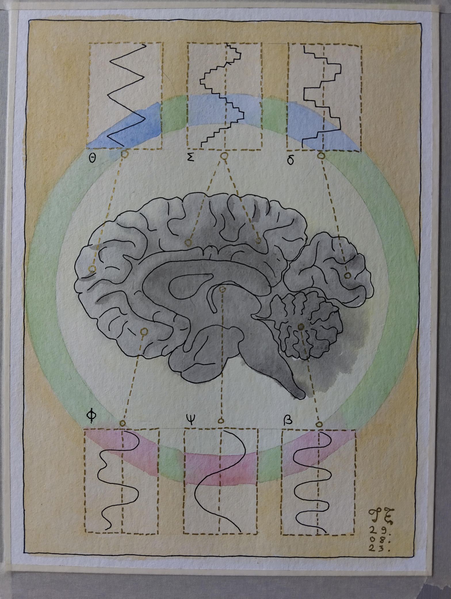
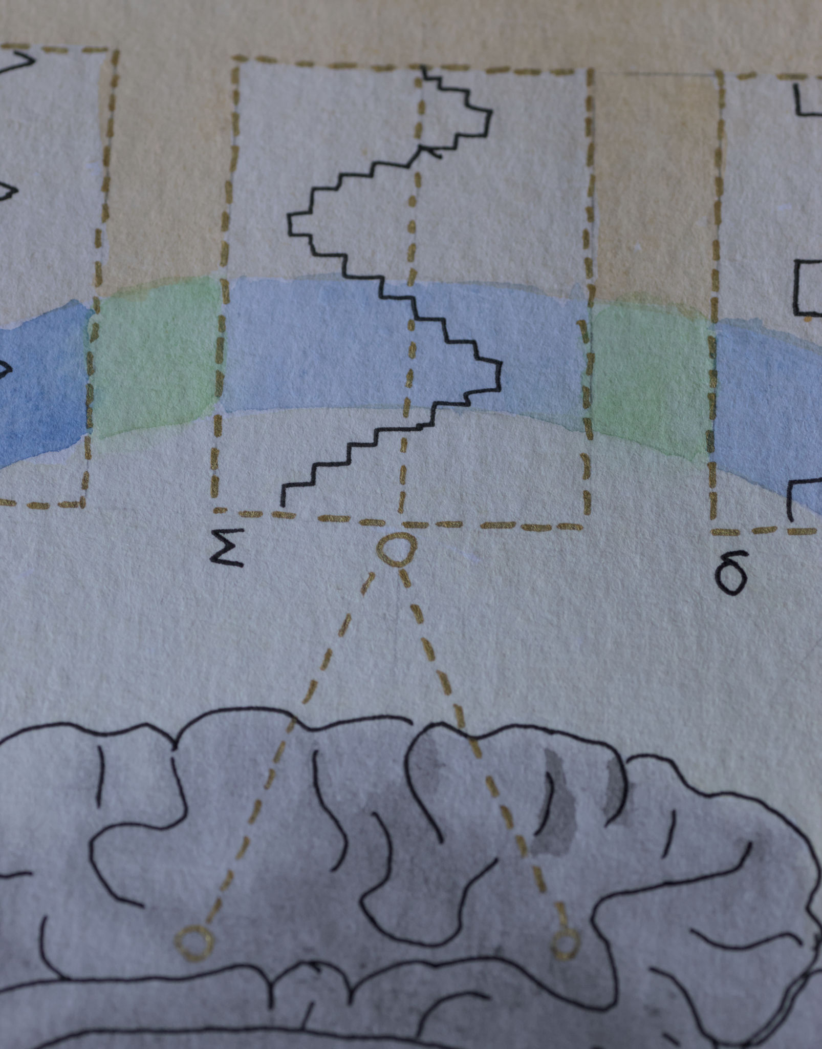
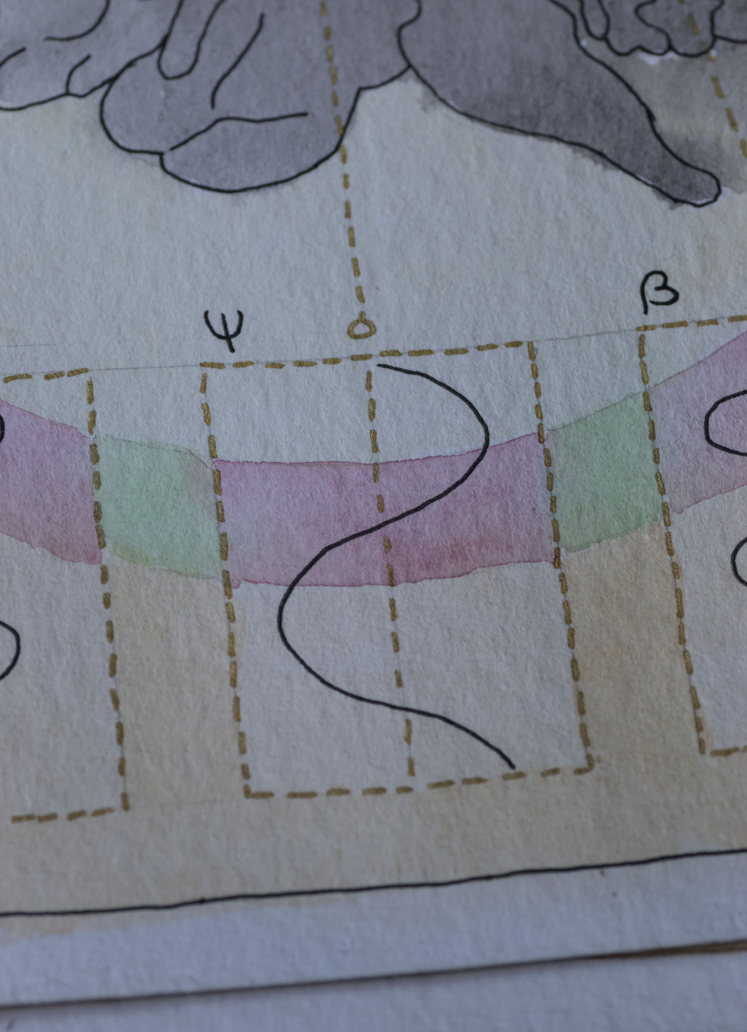
Ajulained, Tauno Erik 14*32 cm, 2023
To program the CH32V003 microcontroller, you will need a programming device that utilizes the proprietary single-wire serial debug interface (SDI). The WCH-LinkE (pay attention to the “E” in the name) is a suitable device for this purpose and can be purchased commercially. This debugging tool is compatible with the CH32V003 and other WCH RISC-V and ARM-based microcontrollers.
I bought mine from here.
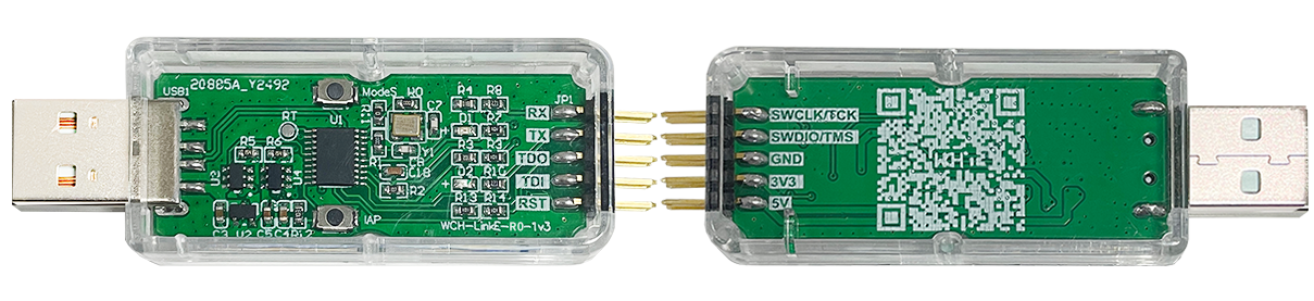
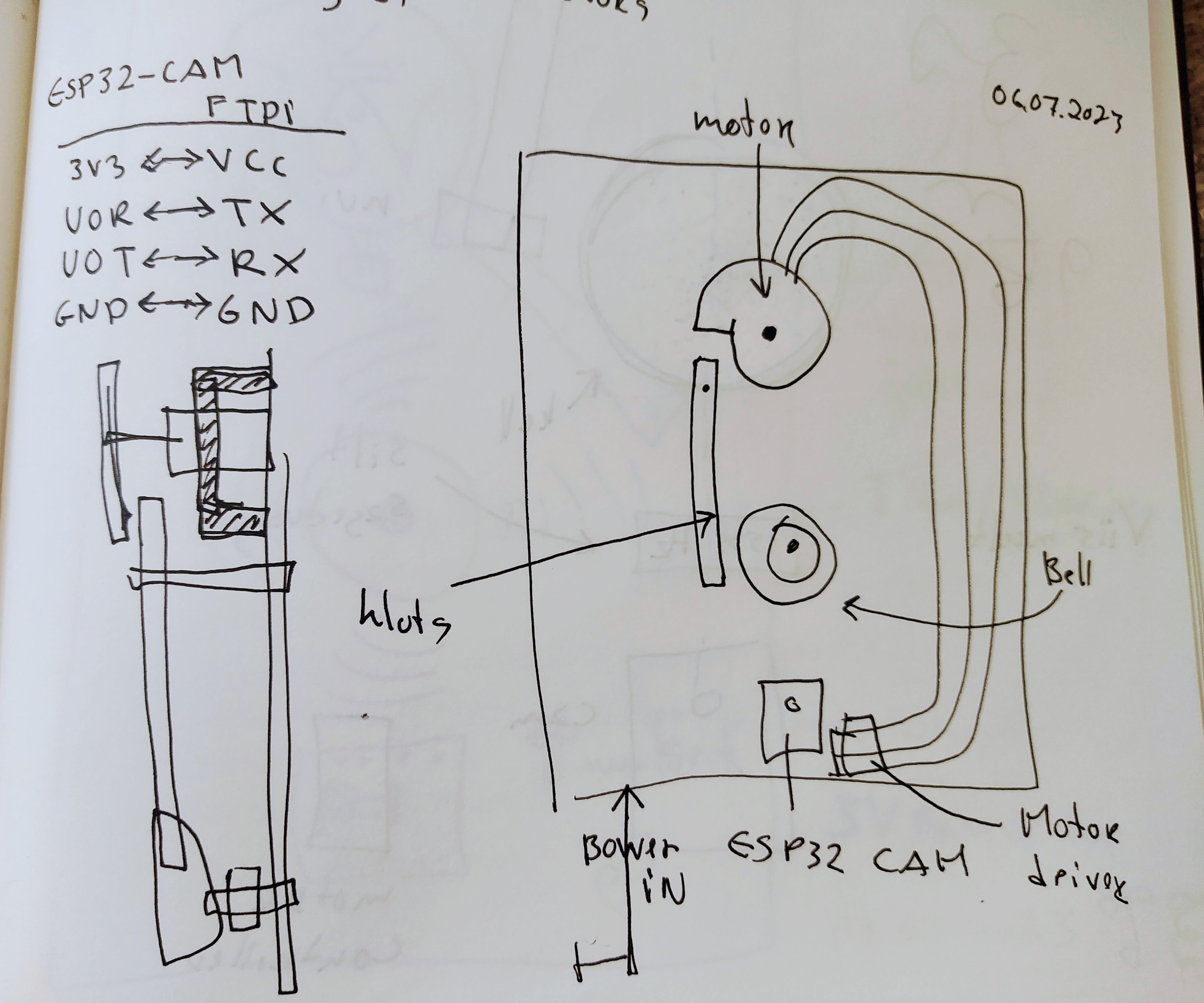
To upload the firmware you should make the following connections to the WCH-LinkE:
If the blue LED on the WCH-LinkE remains illuminated once it is connected to the USB port, it means that the device is currently in ARM mode and must be switched to RISC-V mode initially. There are a few ways to accomplish this:
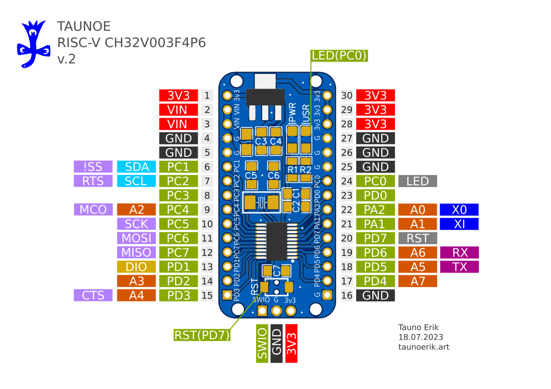
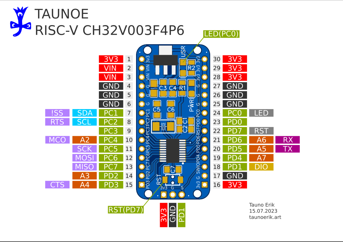
It uses a 1-wire serial debug interface. So we need one pin (PD1) + GND and 3.3V.
| WCH-LinkE | Board |
| SWIO/TMS | PD1/SWIO/ |
| GND | GND |
| 3V3 | 3V |
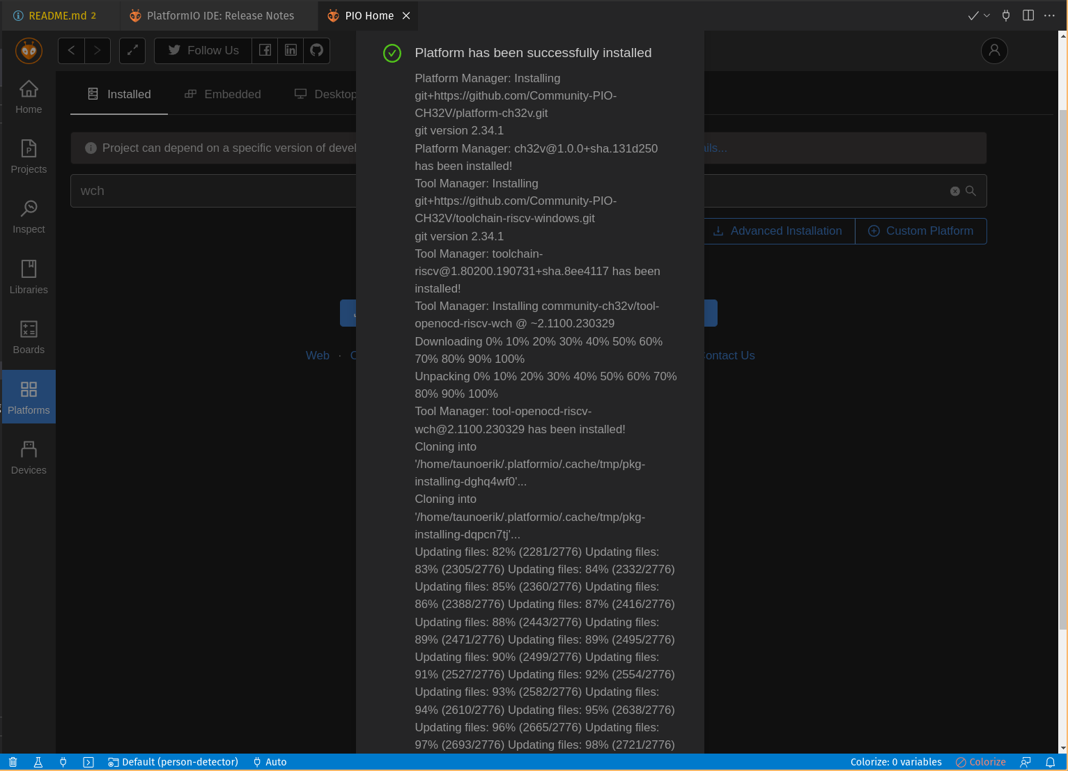
PIO Home -> Platforms -> Advanced platform installation
Add this URL and install.
https://github.com/Community-PIO-CH32V/platform-ch32v.git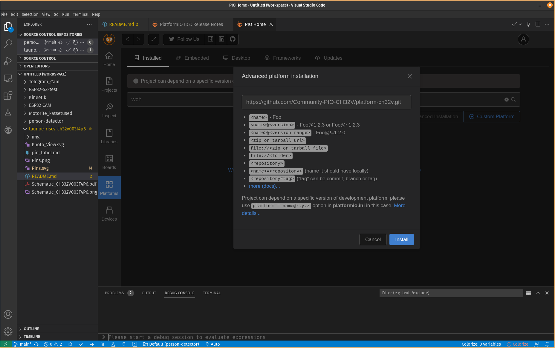
Open and edit /etc/udev/rules.d/99-platformio-udev.rules file:
sudo gedit /etc/udev/rules.d/99-platformio-udev.rulesAdd:
SUBSYSTEM=="usb", ATTR{idVendor}="1a86", ATTR{idProduct}=="8010", GROUP="plugdev"
SUBSYSTEM=="usb", ATTR{idVendor}="4348", ATTR{idProduct}=="55e0", GROUP="plugdev"
SUBSYSTEM=="usb", ATTR{idVendor}="1a86", ATTR{idProduct}=="8012", GROUP="plugdev"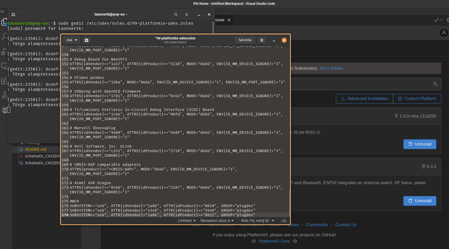
Restart “udev” management tool:
sudo service udev restartStart project:
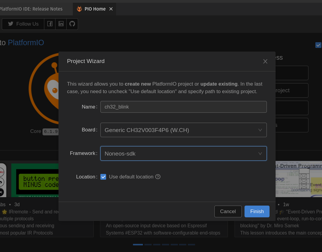
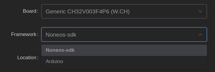
There are available two frameworks for CH32V003F4P6: Noneos-SDK and Arduino
Noneos-SDK Blink code:
#if defined(CH32V00X)
#include <ch32v00x.h>
#elif defined(CH32V10X)
#include <ch32v10x.h>
#elif defined(CH32V20X)
#include <ch32v20x.h>
#elif defined(CH32V30X)
#include <ch32v30x.h>
#endif
#include <debug.h>

#define BLINKY_GPIO_PORT GPIOC
#define BLINKY_GPIO_PIN GPIO_Pin_0
#define BLINKY_CLOCK_ENABLE RCC_APB2PeriphClockCmd(RCC_APB2Periph_GPIOC, ENABLE)

void NMI_Handler(void) __attribute__((interrupt("WCH-Interrupt-fast")));
void HardFault_Handler(void) __attribute__((interrupt("WCH-Interrupt-fast")));
void Delay_Init(void);
void Delay_Ms(uint32_t n);

int main(void)
{
	NVIC_PriorityGroupConfig(NVIC_PriorityGroup_2);
	SystemCoreClockUpdate();
	Delay_Init();

	GPIO_InitTypeDef GPIO_InitStructure = {0};

	BLINKY_CLOCK_ENABLE;
	GPIO_InitStructure.GPIO_Pin = BLINKY_GPIO_PIN;
	GPIO_InitStructure.GPIO_Mode = GPIO_Mode_Out_PP;
	GPIO_InitStructure.GPIO_Speed = GPIO_Speed_50MHz;
	GPIO_Init(BLINKY_GPIO_PORT, &GPIO_InitStructure);

	uint8_t ledState = 0;
	while (1)
	{
		GPIO_WriteBit(BLINKY_GPIO_PORT, BLINKY_GPIO_PIN, ledState);
		ledState ^= 1; // invert for the next run
		Delay_Ms(1000);
	}
}

void NMI_Handler(void) {}
void HardFault_Handler(void)
{
	while (1)
	{
	}
}
Add CH32 Board Manager URL:
https://raw.githubusercontent.com/openwch/board_manager_files/main/package_ch32v_index.json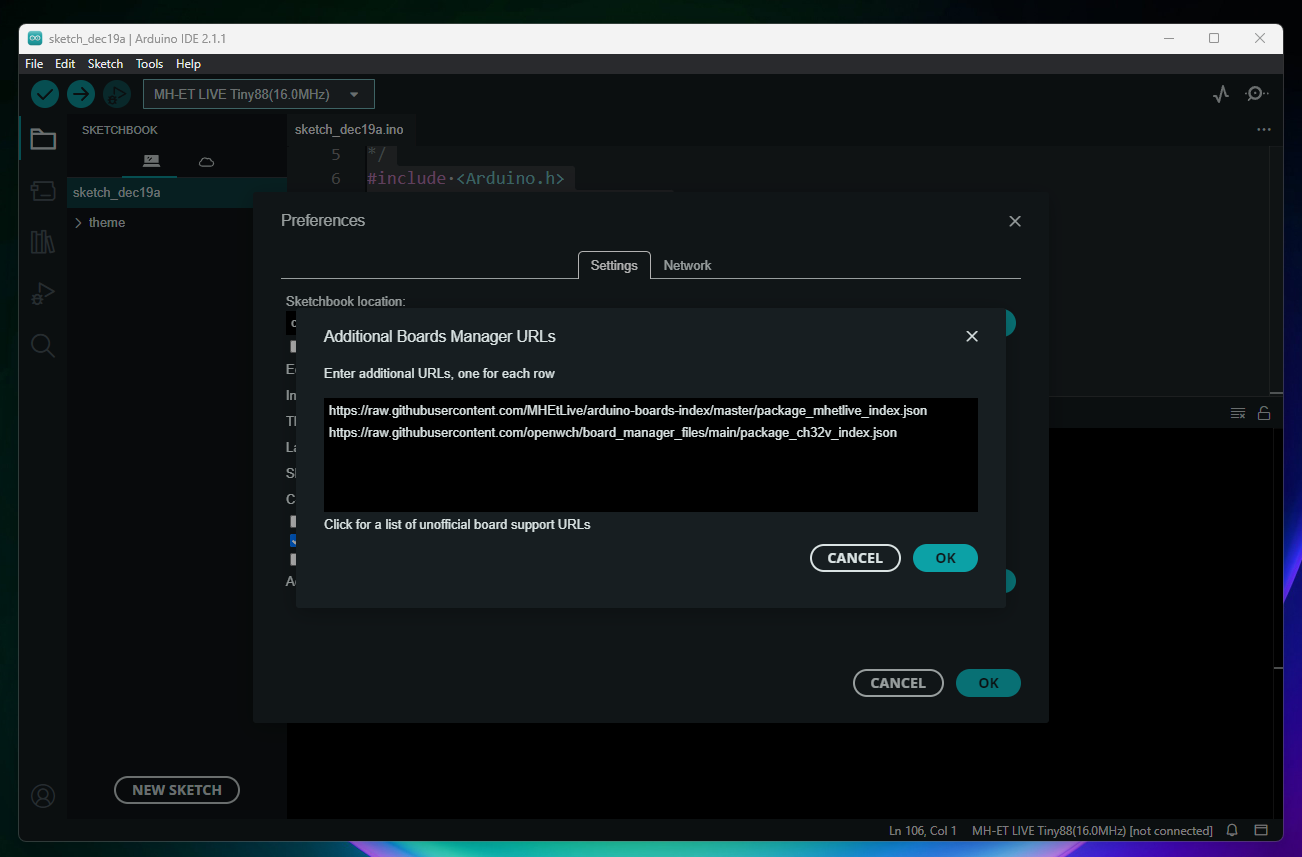
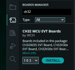
Open Board Manager and Search: CH32 MCU EVT Boards and install it
After upload I need to reset the board to make it blink.
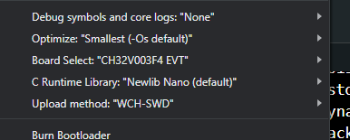
#define LED_BUILTIN PC0

// the setup function runs once when you press reset or power the board
void setup() {
  // initialize digital pin LED_BUILTIN as an output.
  pinMode(LED_BUILTIN, OUTPUT);
}

// the loop function runs over and over again forever
void loop() {
  digitalWrite(LED_BUILTIN, HIGH);
  delay(500);
  digitalWrite(LED_BUILTIN, LOW);
  delay(500);
}

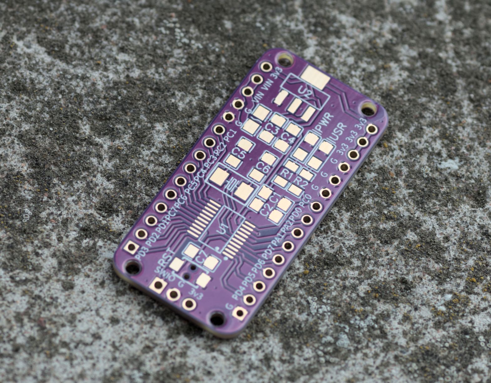
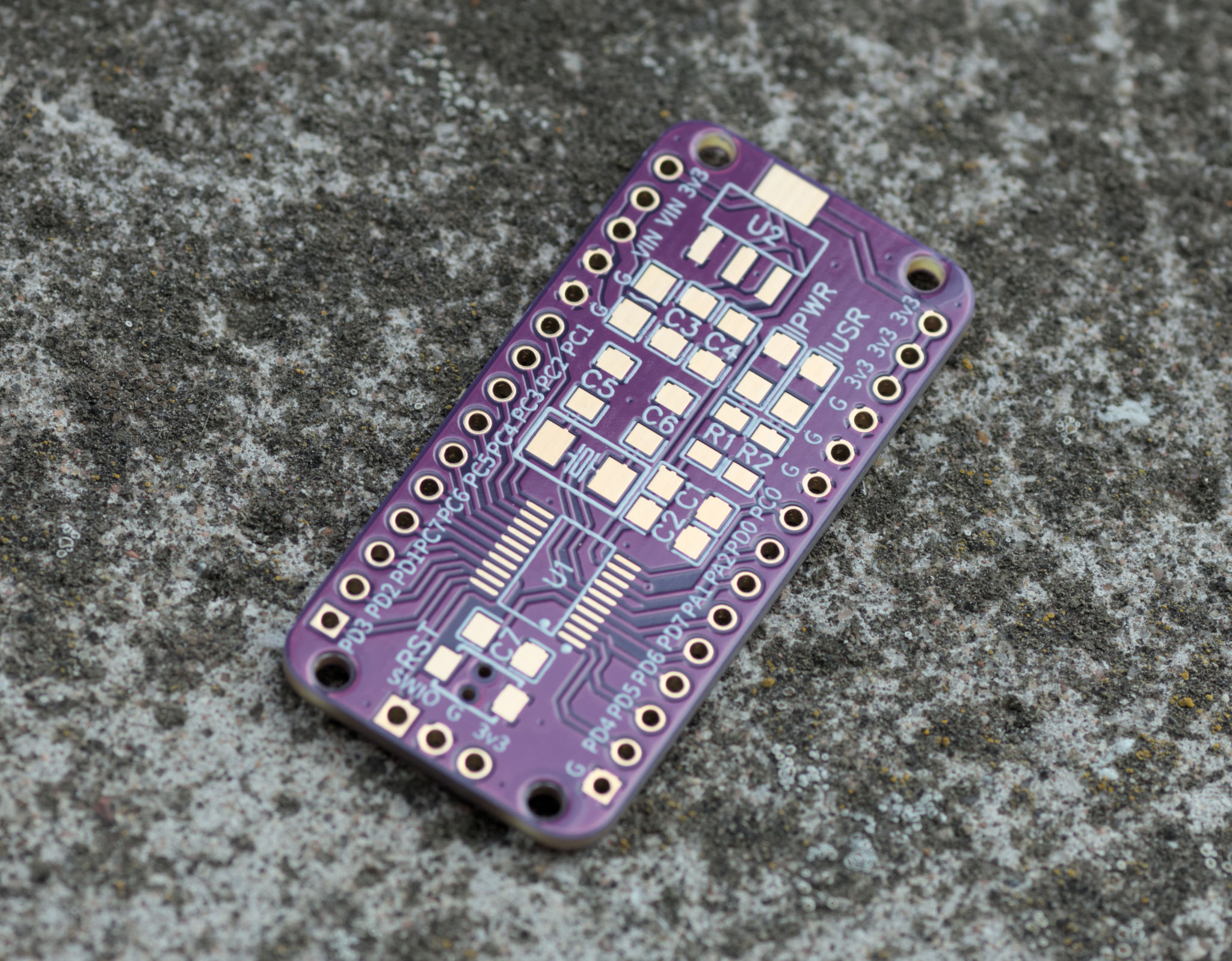
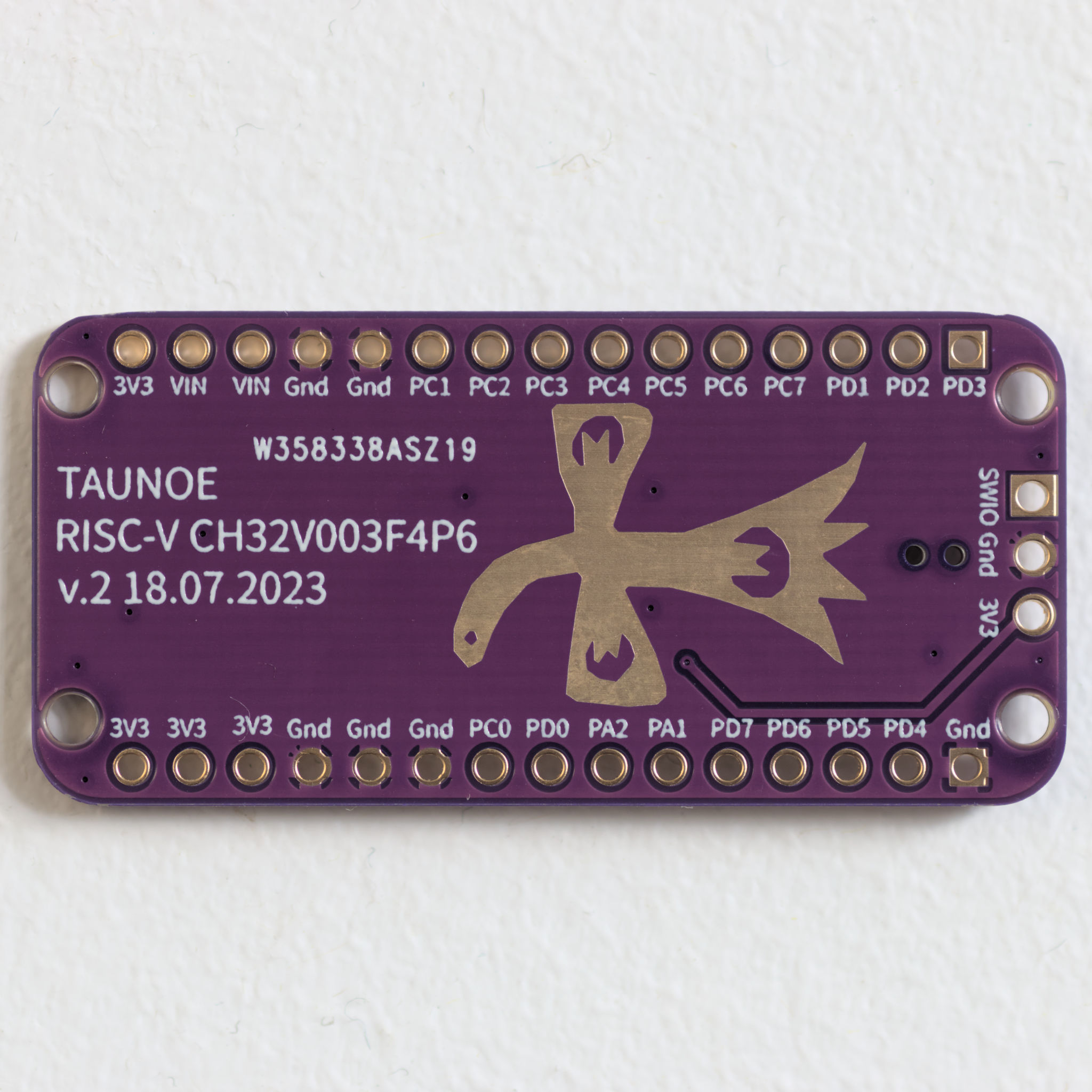
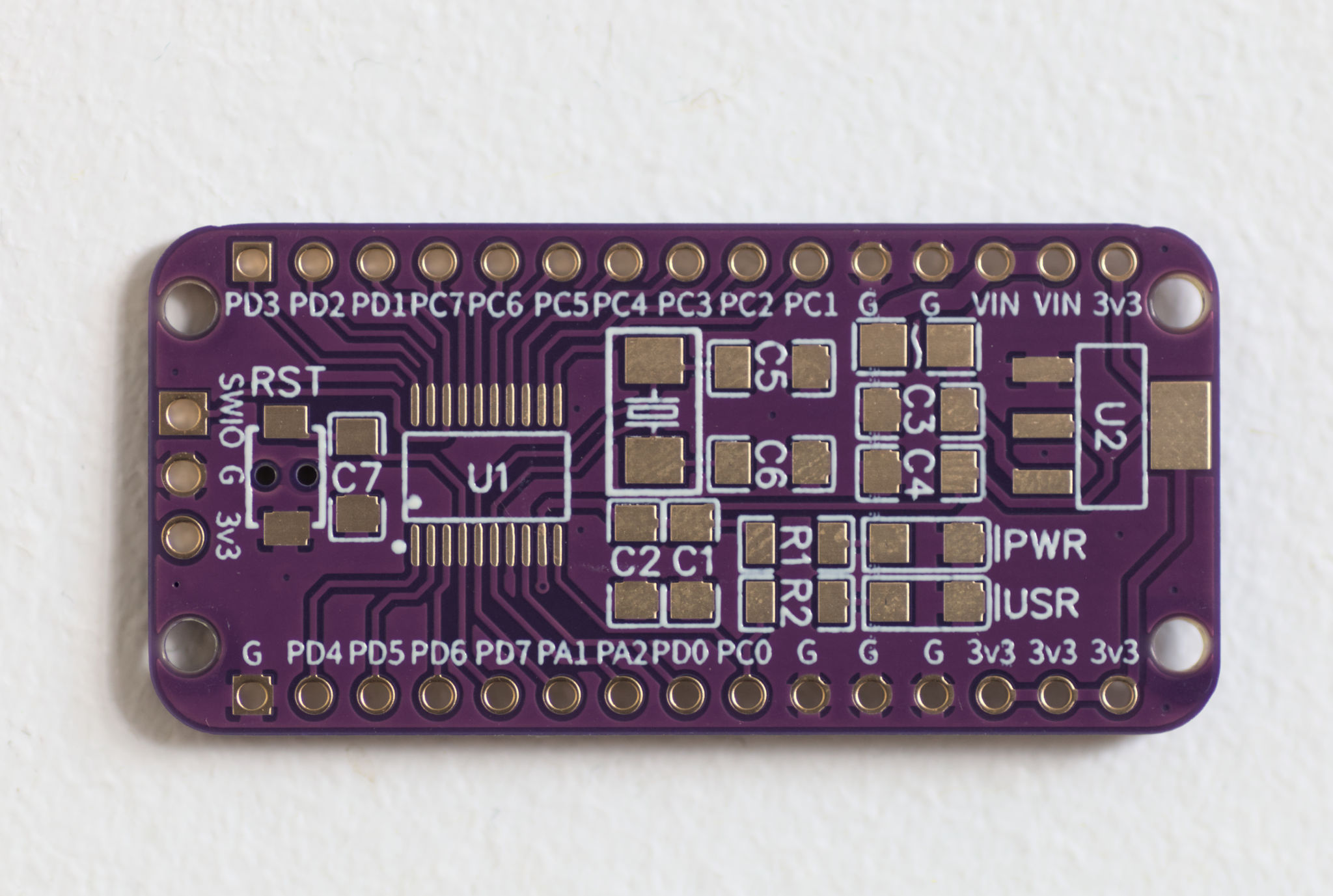
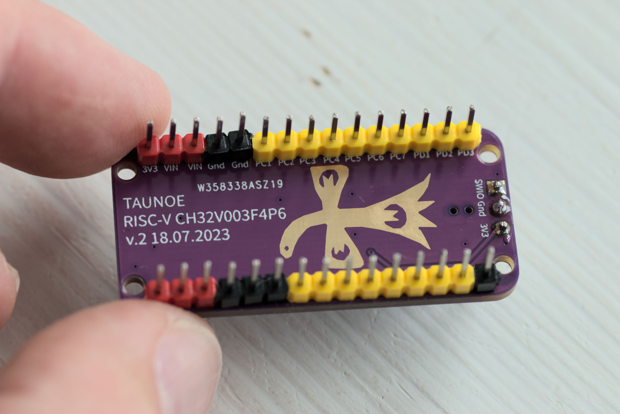
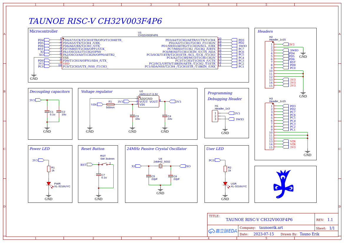
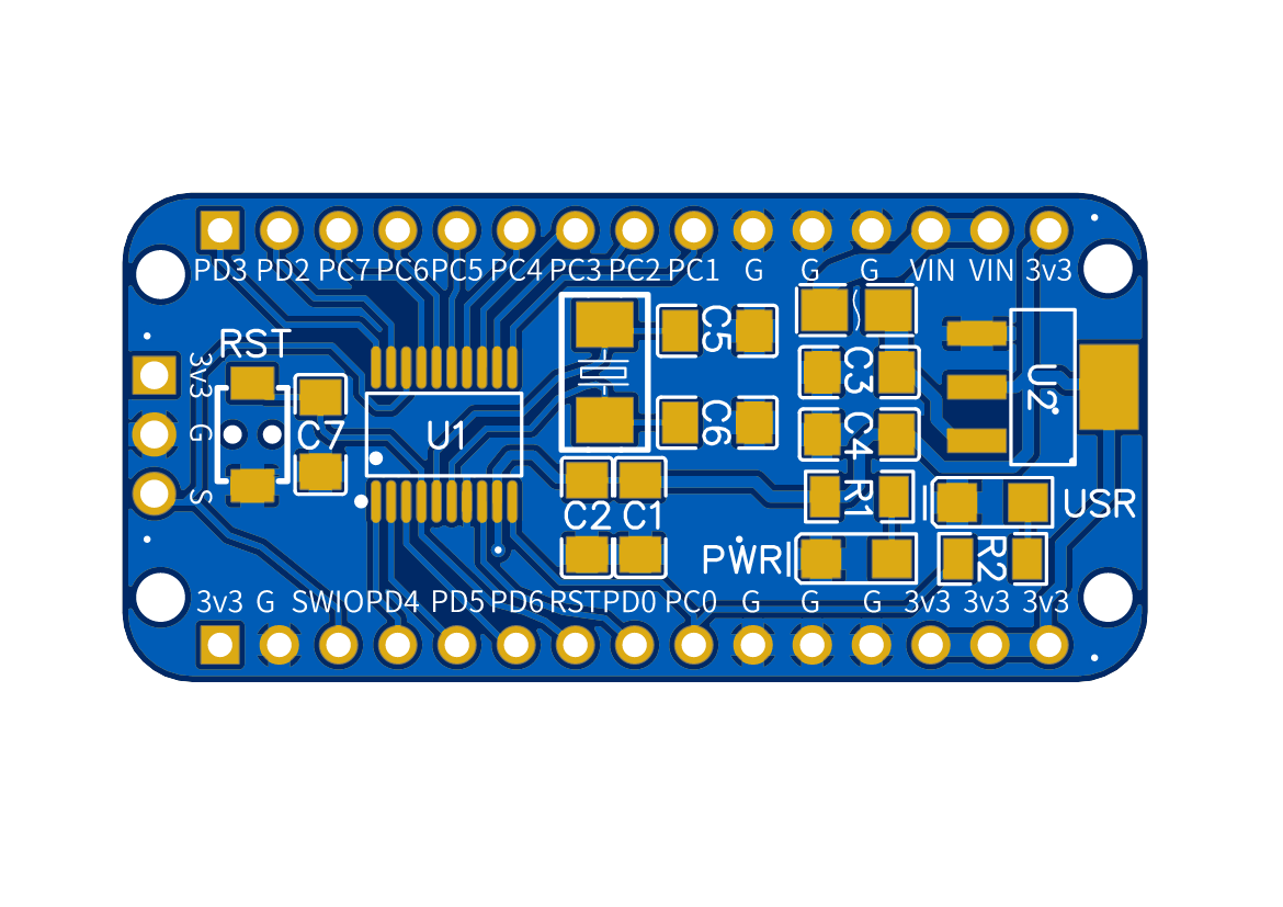
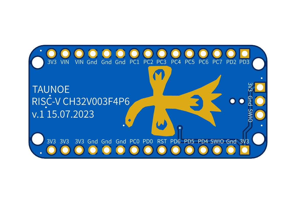
PCBs arrived for my RISC-V CH32V003F4P6 development board.
As always PCBway services are very fast. It was the last part I ordered and the first, that arrived.
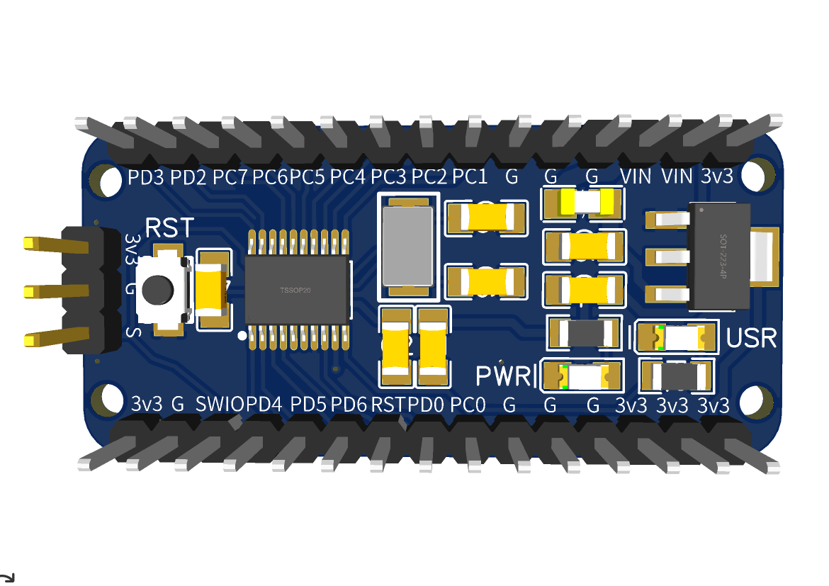
Soldered one of the boards together. So far it works and I’m surprised that I soldered the LEDs in the correct orientation on the first try. I also like to use coloured headers.
PCBs are available at PCBway shared project website.
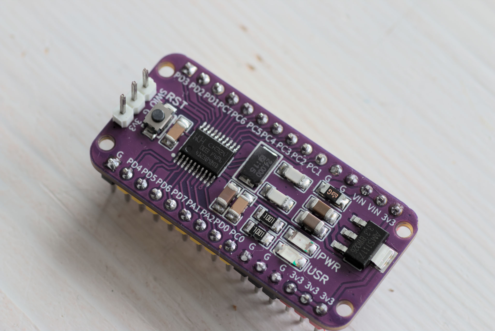
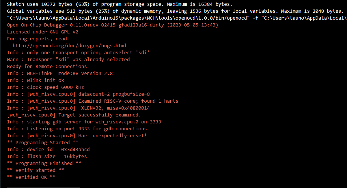
Demo Blink code works!
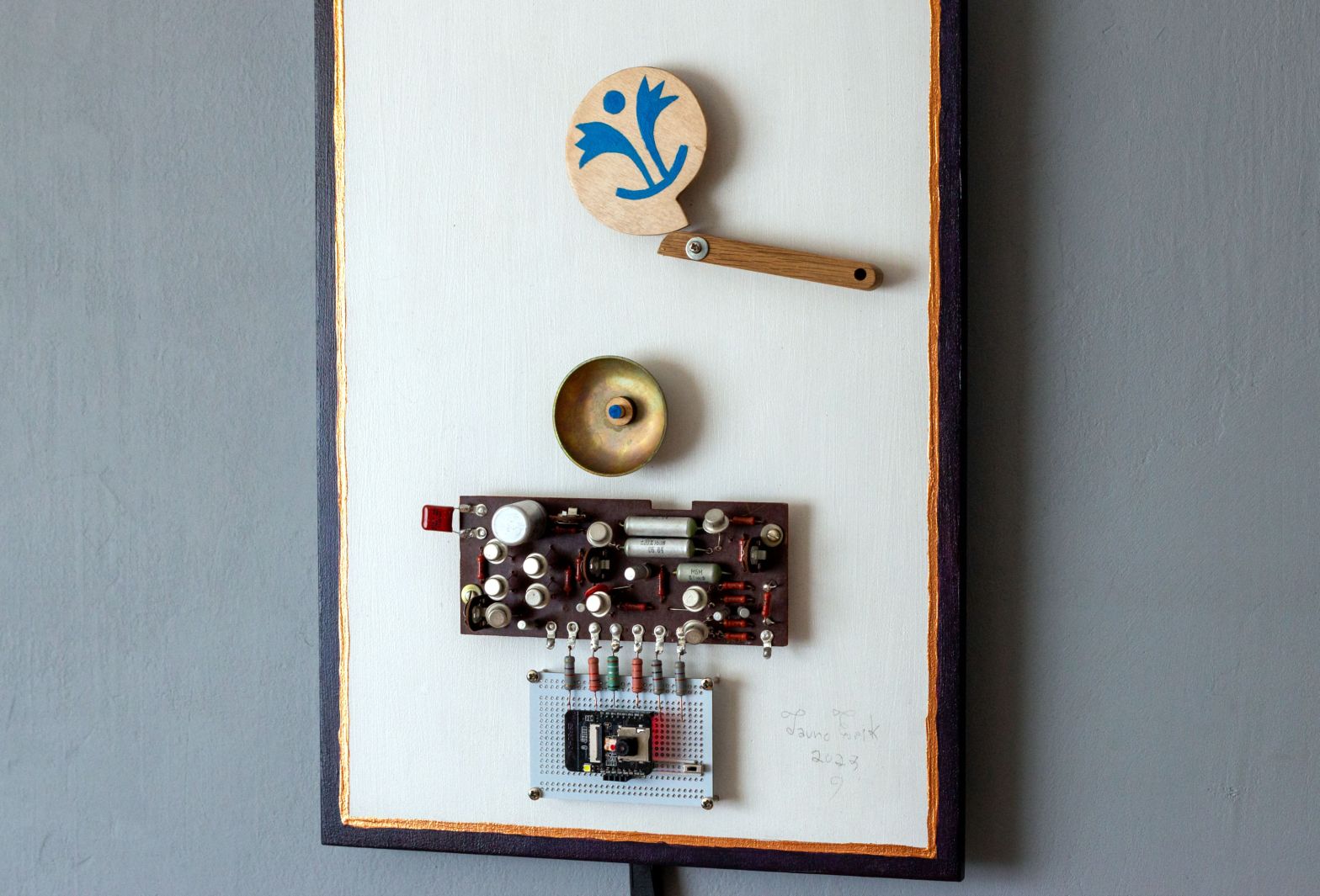
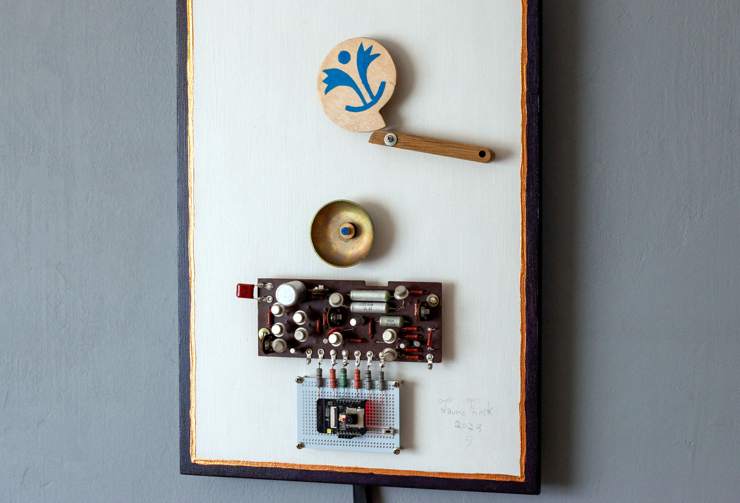
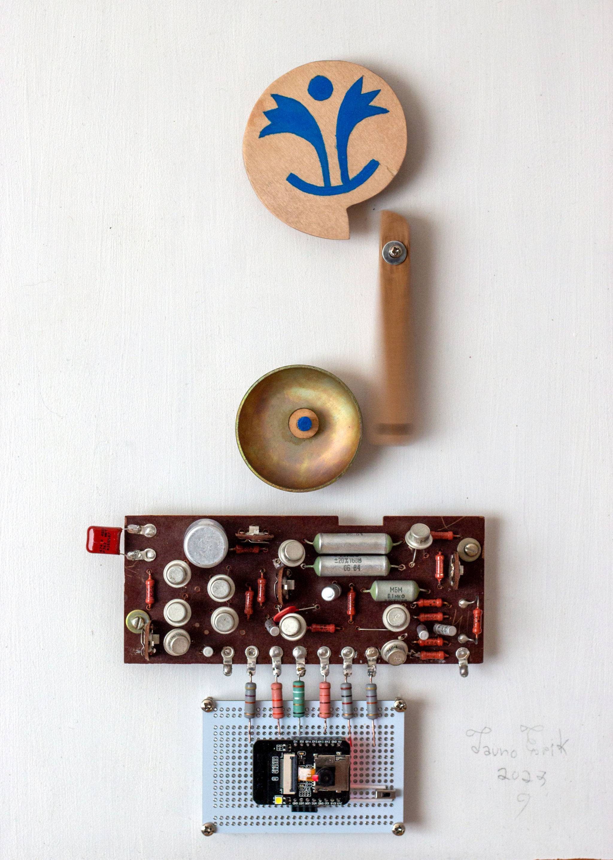
From the Latin tintinnabulum – “a bell”. The name is inspired by Estonian composer Arvo Pärt music.
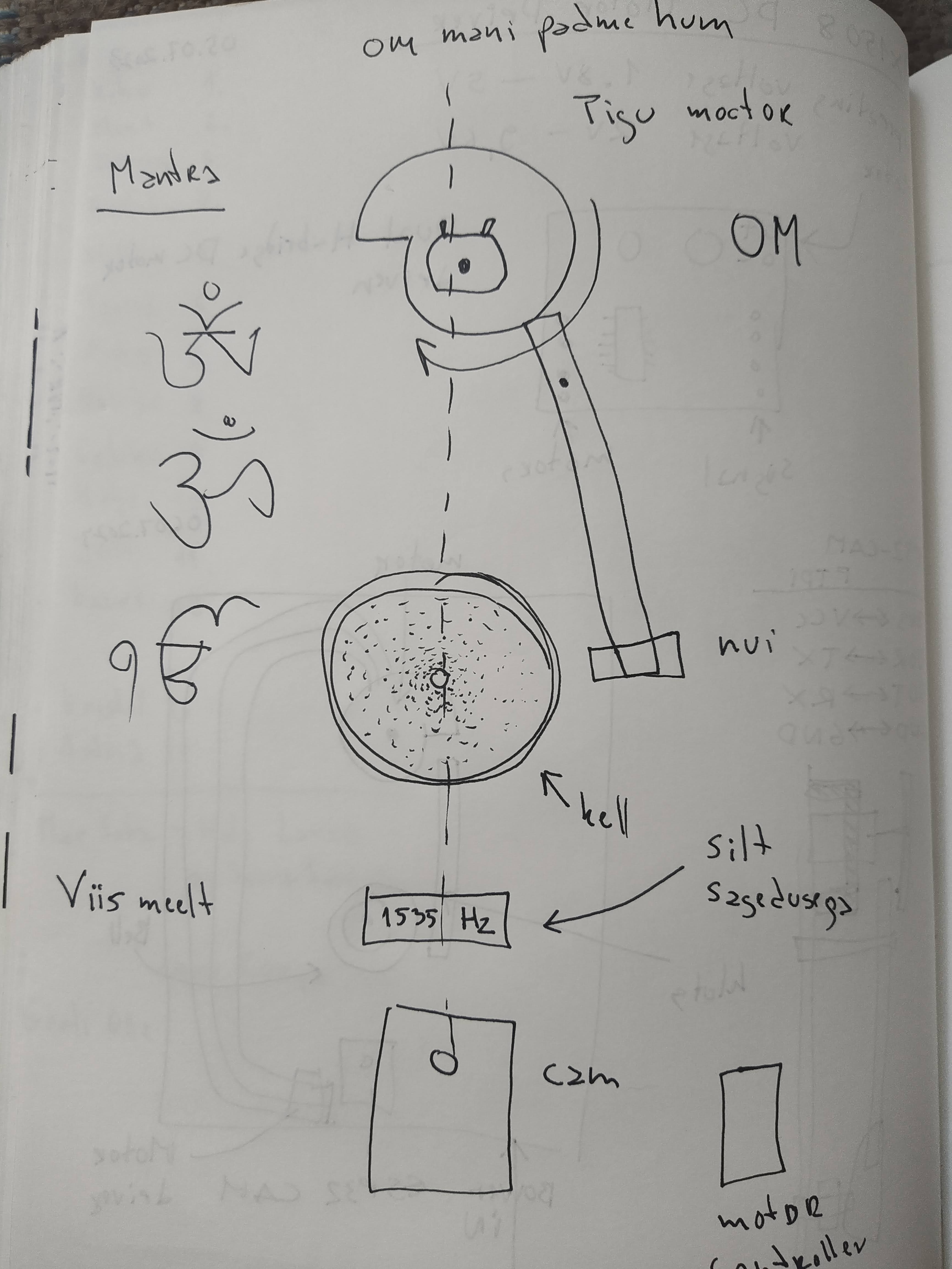
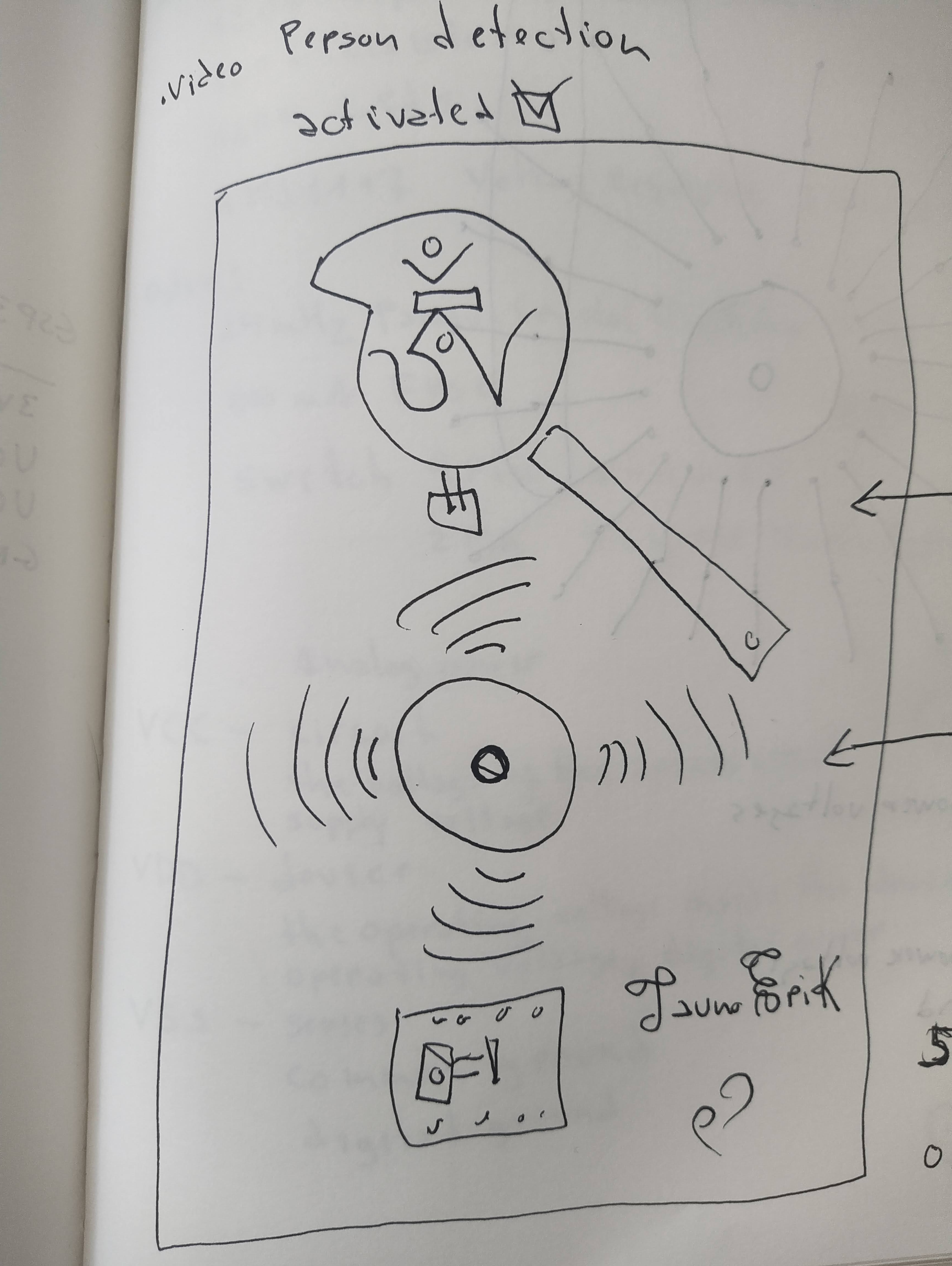
This is my electronic sculpture with a TinyML person detection function.


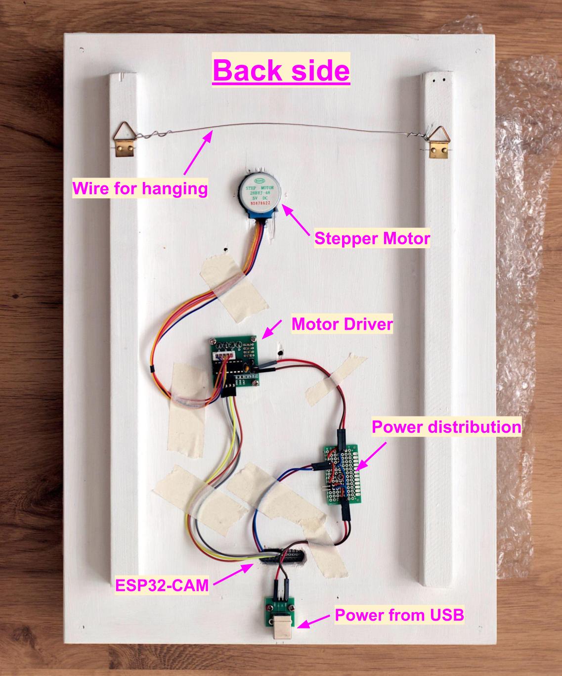
The sculpture takes images, analyses them and when it detects a person on them it will activate the simple automata mechanism to ring the bell. The bell rings at a frequency 2578Hz.
The brain is an ESP32-CAM module. The TinyML model is trained with Edge Impulse. Using the COCO dataset. I used PlatformIO for programming. It does not record or collect images that it does. And not connected to WiFi.
The motivation to do this came from the desire to learn more about automata and control the real world through programming.
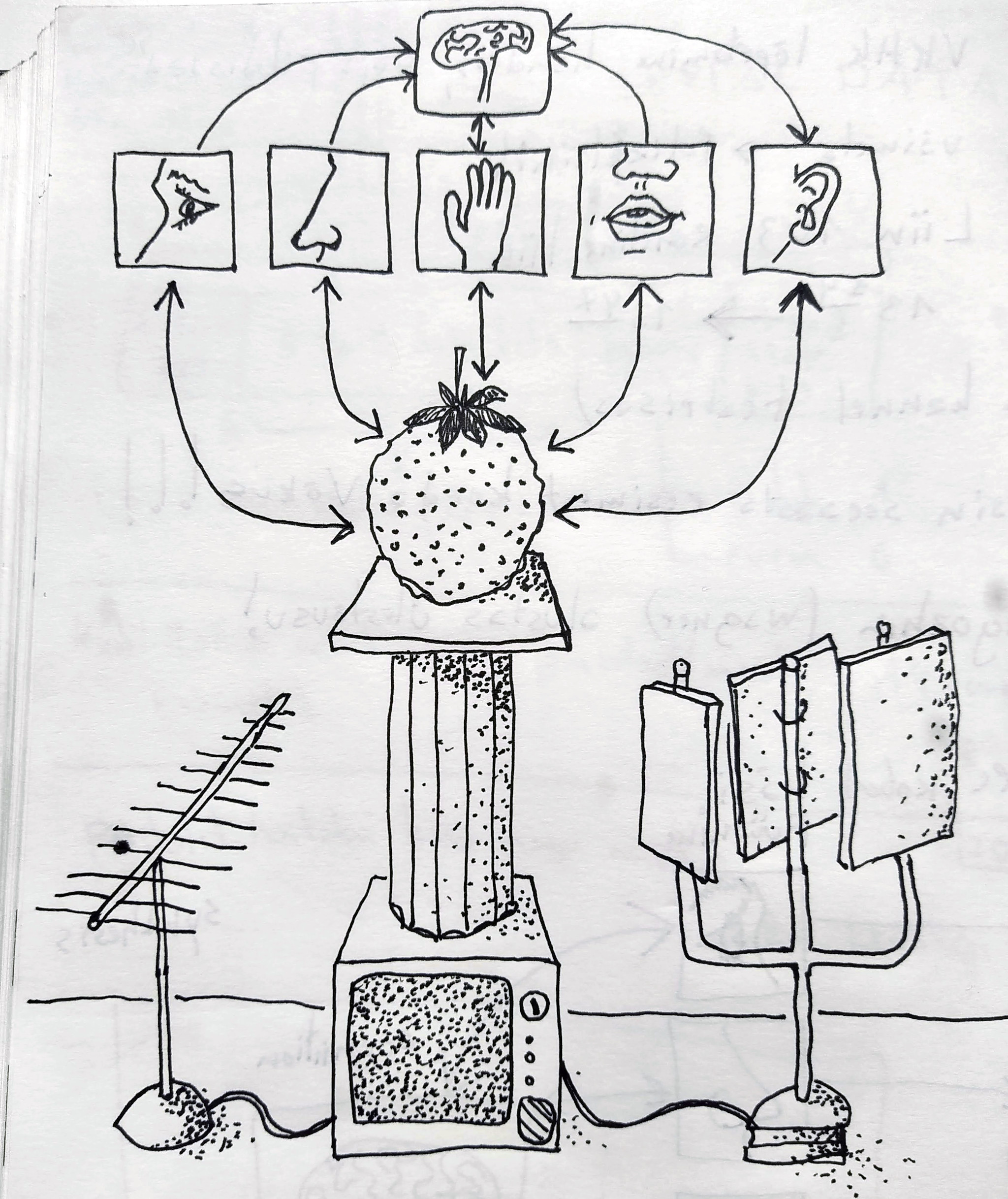
Humans have five senses to interact with the world. And art should use all of them to communicate with the human soul.


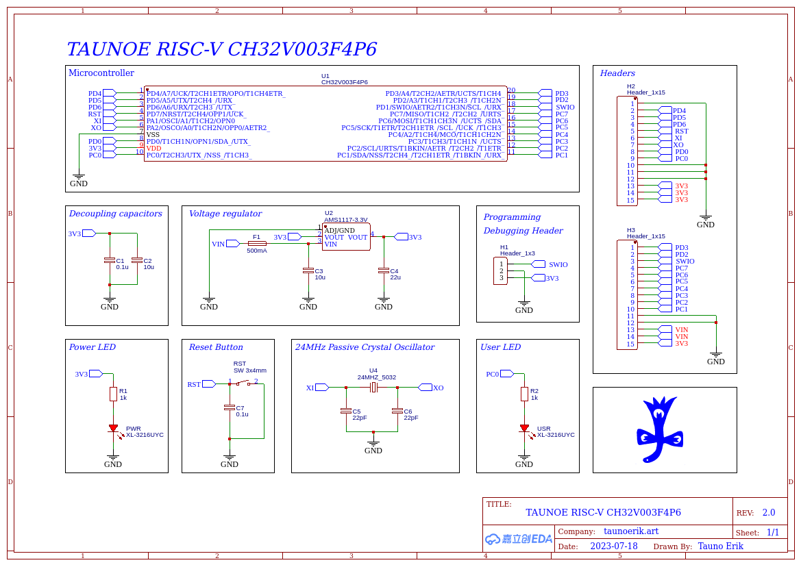
Designed my own development board version for the famous 10-cent microcontroller of RISC-V CH32V003F4P6. Now I plan to order PCBs. Then assemble it and test it.
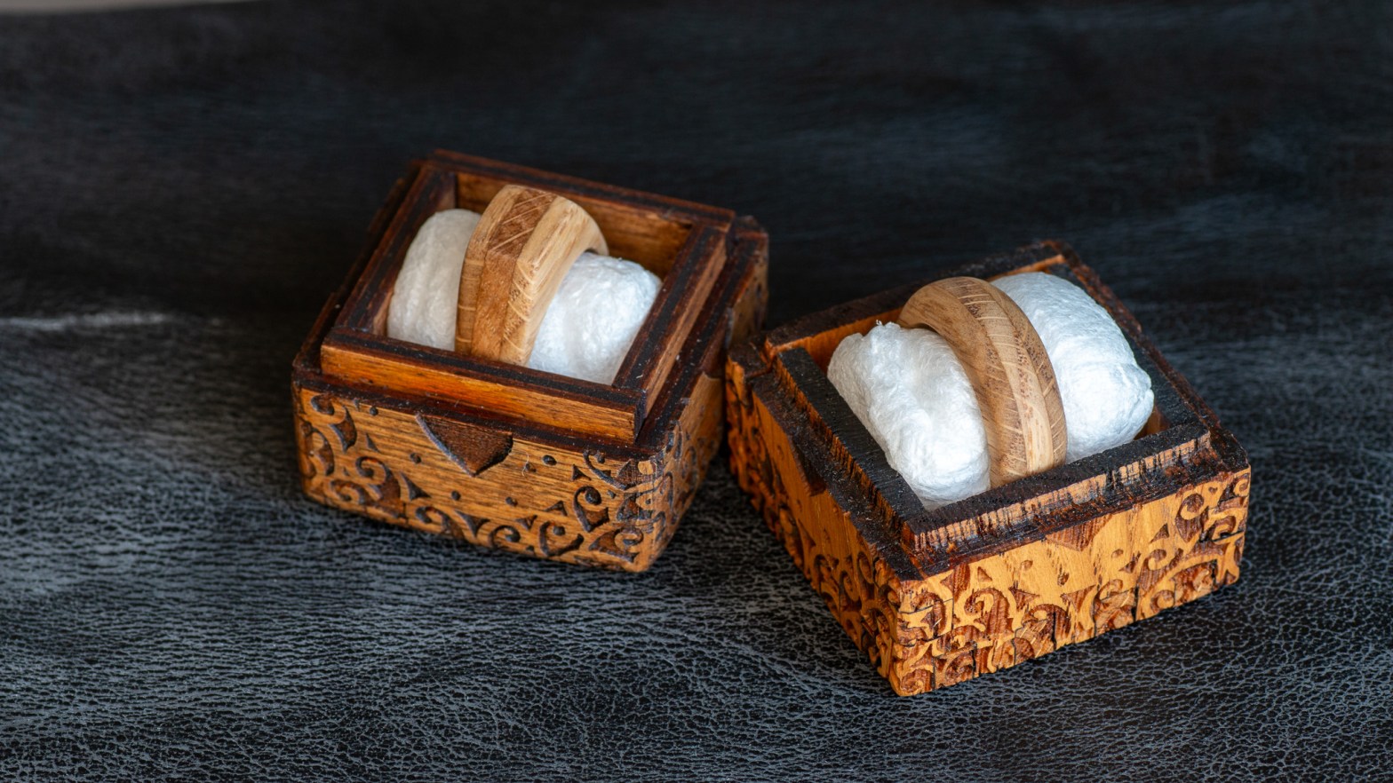
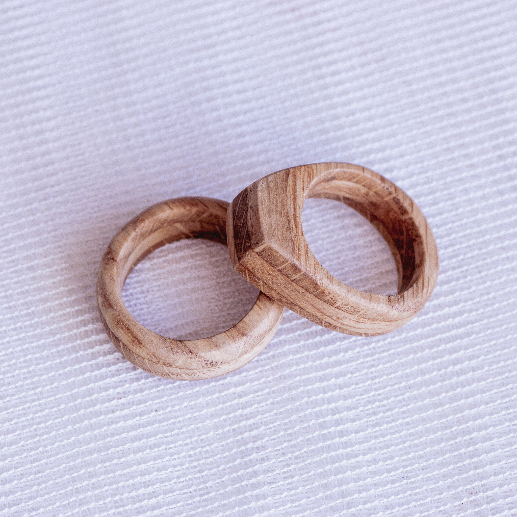
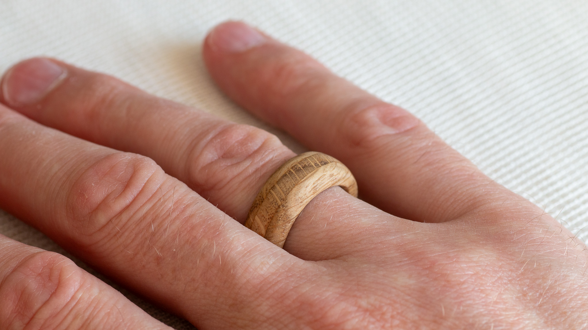
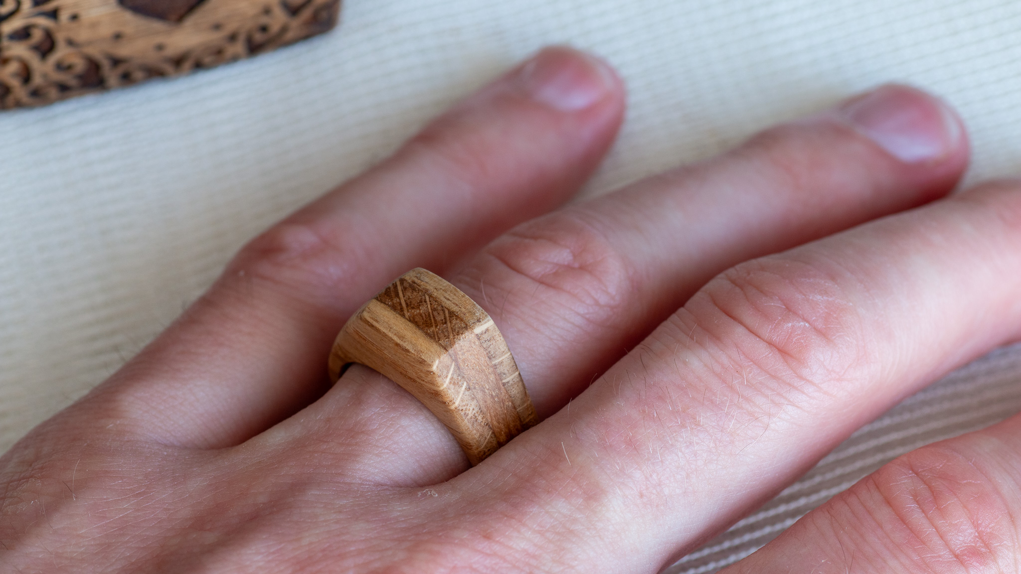
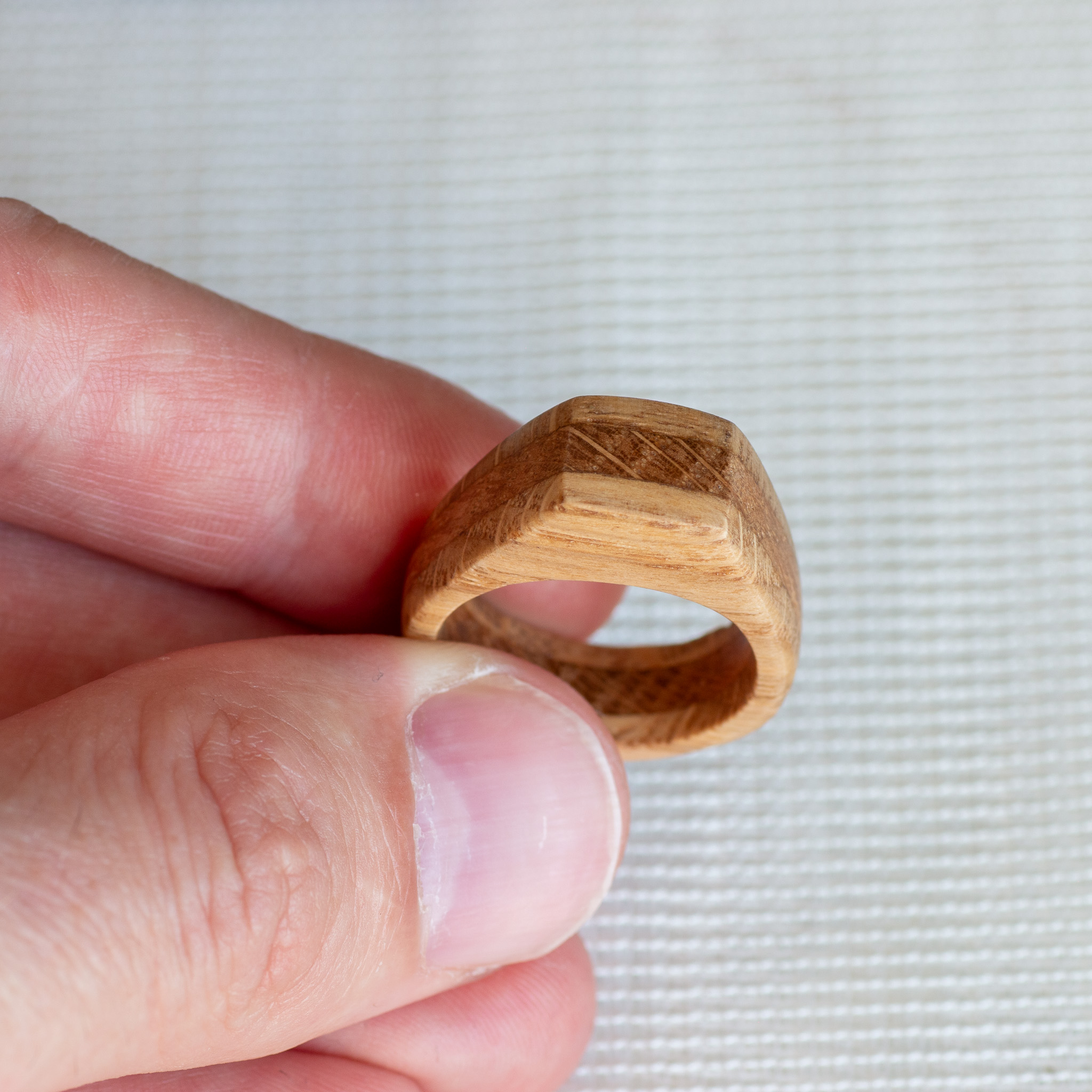
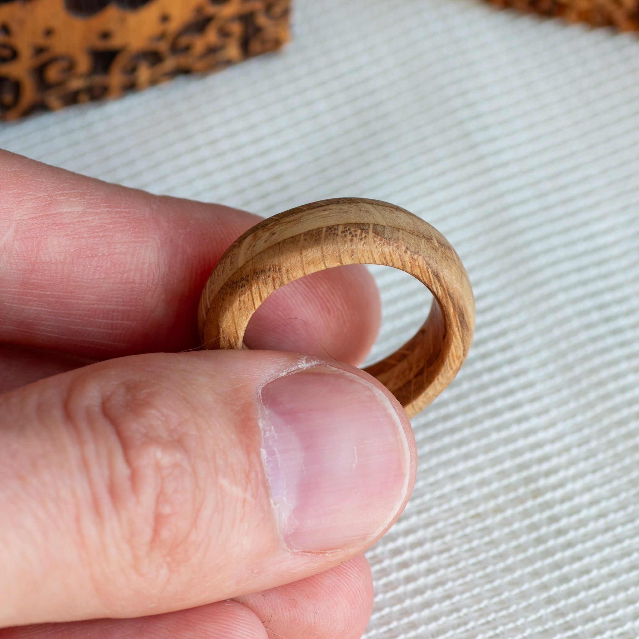
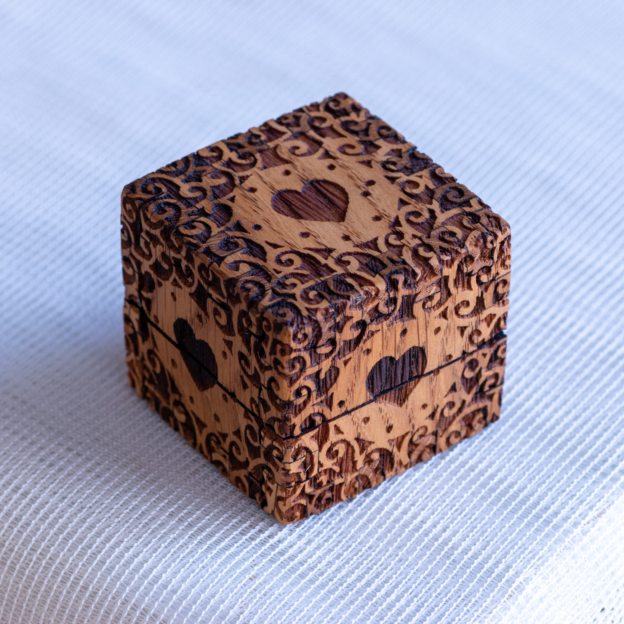
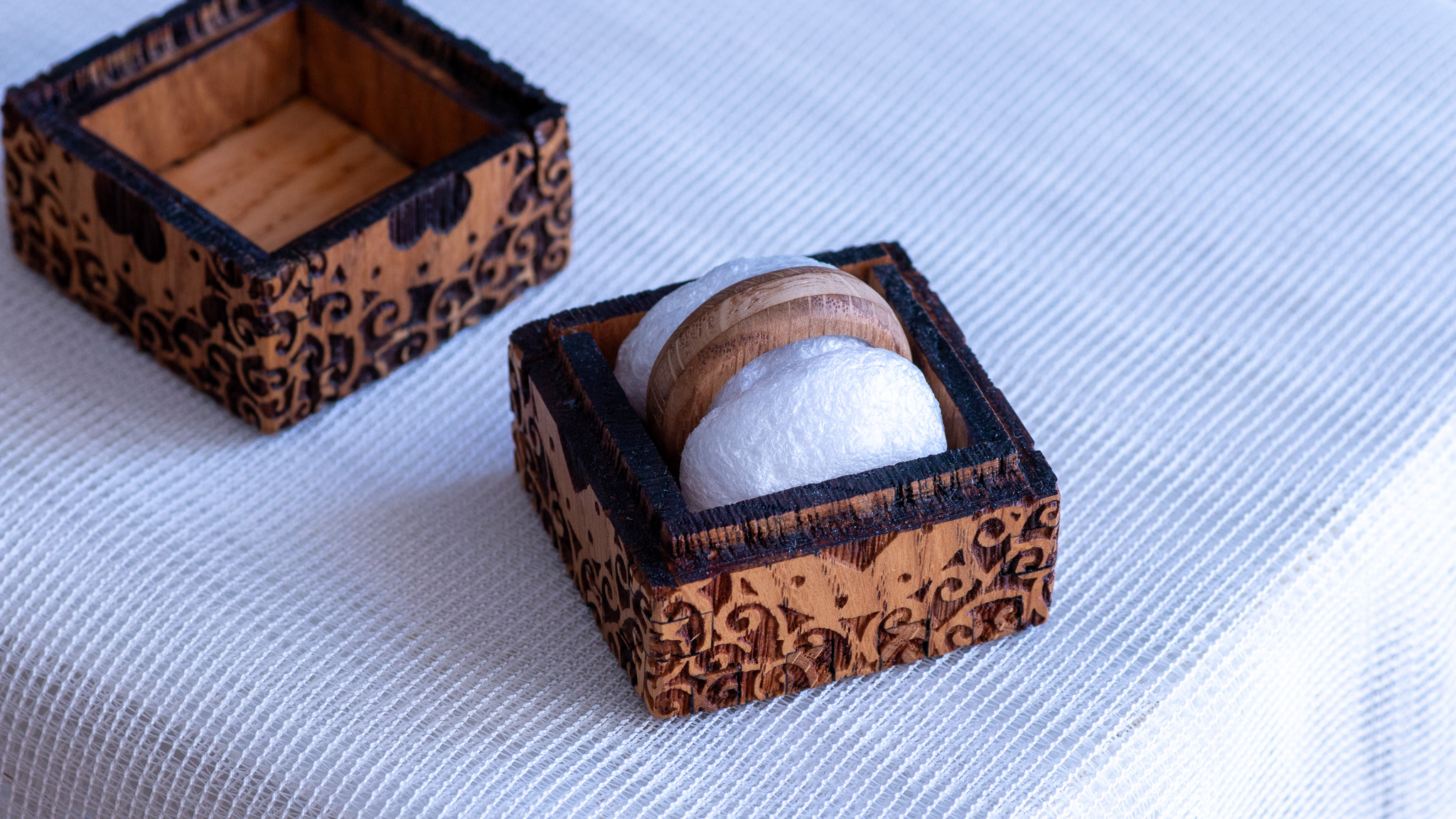
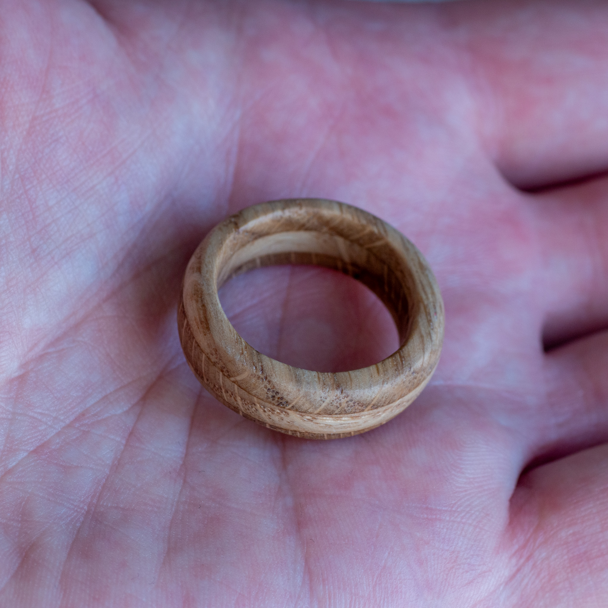
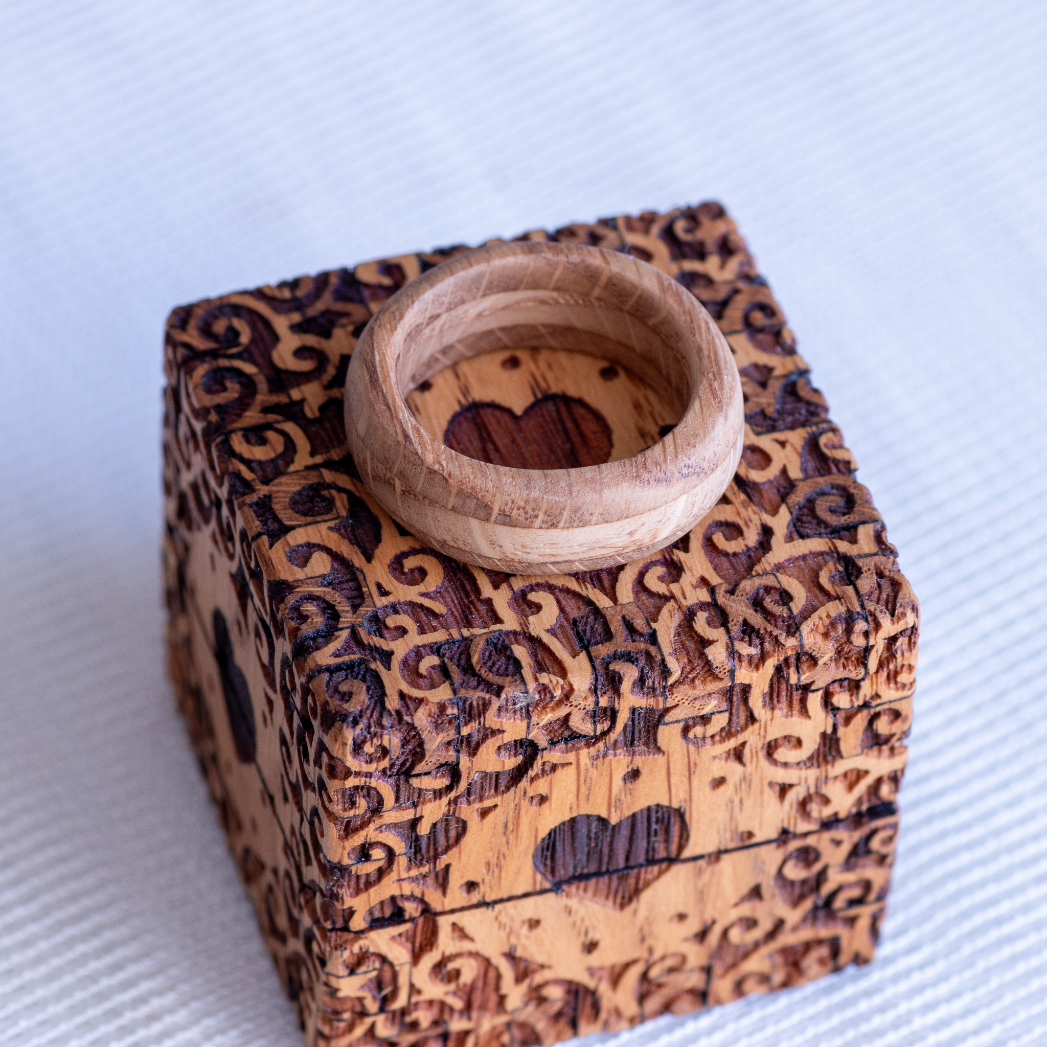
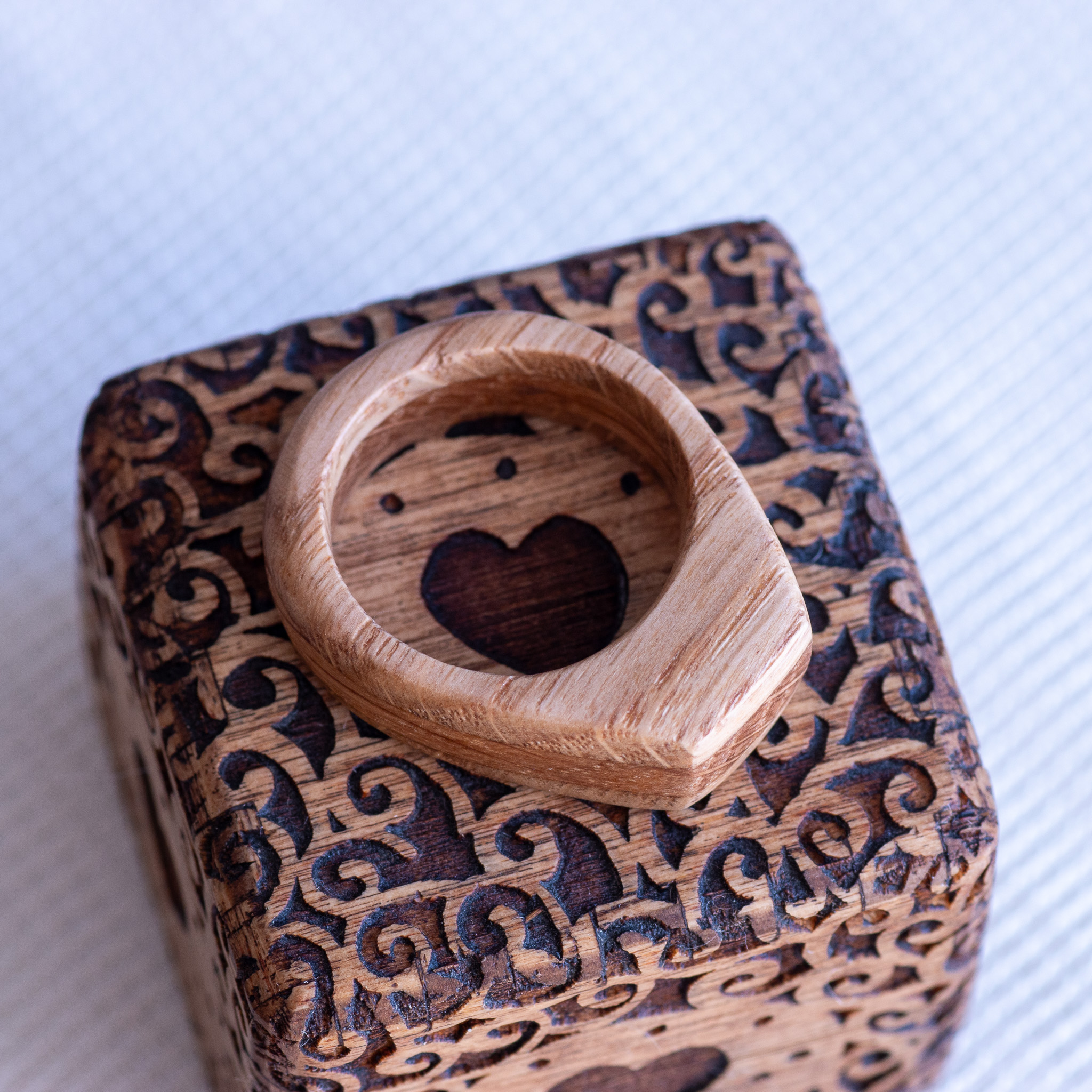
I made two rings from oak wood. I had already made the boxes for the ring.


Most of the pictures are from the news.


These are notes to myself. I fill them in over time as I work through the material.
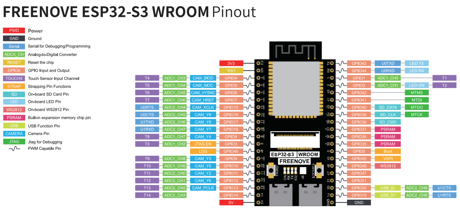
I recently bought two Freenove ESP32-S3-Wroom boards. One thing you immediately notice is that they have two USB-C ports. One is USB-UART and the other is USB-OTG. USB-UART is like the regular USB on this kind of board. To program them and Serial.print() and etc. This USB acts only as a device. USB-UART uses an external USB-to-serial chip. This is on all older boards.
USB-OTG is something new to me. OTG means On The Go. The USB-OTG can be a device and also a host. That means we can connect other USB devices (USB flash drives, digital cameras, mouse or keyboards) to them. USB-OTG on this board is an integrated USB peripheral. No external chip. Directly connected. It allows emulating keyboards, disk drives, USB sticks etc.

My platformio.ini file:
[env:esp-wrover-kit]
platform = espressif32
board = esp32-s3-devkitc-1
framework = arduino
monitor_speed = 115200
upload_port = /dev/ttyACM0
;upload_speed = 921600
board_build.partitions = partitions_custom.csv
build_flags =
-DBOARD_HAS_PSRAM
-mfix-esp32-psram-cache-issue
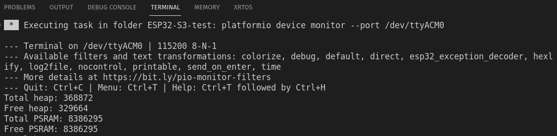
board_build.arduino.memory_type = dio_opiCode to test PSRAM size:
#include <Arduino.h>

void setup() {
  Serial.begin(115200);
}

void loop() {
  Serial.printf("Total heap: %d\n", ESP.getHeapSize());
  Serial.printf("Free heap: %d\n", ESP.getFreeHeap());
  Serial.printf("Total PSRAM: %d\n", ESP.getPsramSize());
  Serial.printf("Free PSRAM: %d\n", ESP.getFreePsram());
  delay(5000);
}
And result:
| Pin | Default |
| GPIO0 | Pull-up |
| GPIO3 | |
| GPIO45 | Pull-down |
| GPio46 | Pull-down |
Care must be taken with these pins touring resetting/booting/flashing. Because ESP32 reads this these pins state. Are they High or Low and stores this info internally to configure its settings. And when they are wrong, then there can be problems.
After resetting/flashing is finished these pins work like regular GPIO pins.
OPI – Octal SPI (Serial Peripheral Interface)
PSRAM – pseudo-static random-access memory
Pins: GPIO35-37 are used by OPI PSRAM (8MB external Flash). When PSRAM is not used they can be used as normal GPIOs.
There are two ways to use an SD card:
SPI interface – uses 4 pins
SDMMC interface has a one-bit bus mode (uses 3 pins) and a four-bit bus mode (uses 6 pins).
Four-bit mode is the fastest. One-bit mode is about 80% of the four-bit mode and SPI is about 50%.
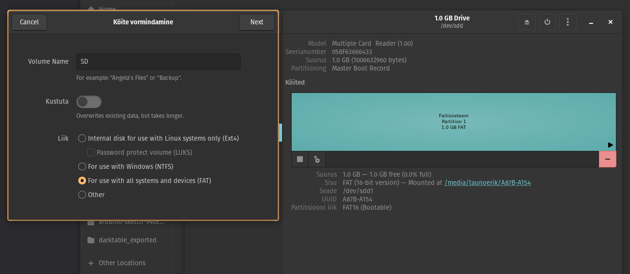
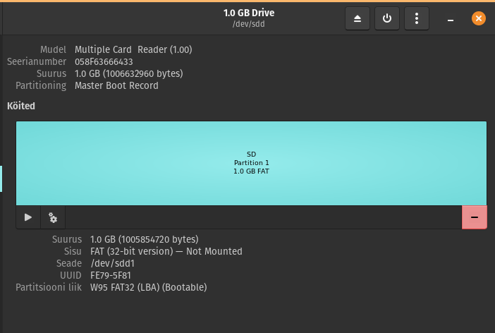
Format the 1GB micro SD card to FAT (or FAT32). Allocation unit size 16K.
SDcard uses SDMMC (Secure Digital Multi Media Card interface).
Use “SD_MMC.h” lib.
Used example code. It writes the files but does not print anything into the serial monitor.
Modes:
Wifi.begin(ssid, password,channel, bssid, connect)
ssid: WiFi hotspot name
password: WiFi hotspot password
channel: WiFi hotspot channel number; communicating through the specified channel; optional parameter
bssid: mac address of WiFi hotspot, optional parameter
connect: optional boolean parameter, defaulting to true. If set as false, then ESP32-S3 won’t connect to WiFi.
Wifi.config(local_ip, gateway, subnet, dns1, dns2): set static local IP address.
local_ip: station fixed IP address.
subnet:subnet mask
dns1,dns2: optional parameter. define IP address of domain name server
Borad manager URL:
https://raw.githubusercontent.com/espressif/arduino-esp32/gh-pages/package_esp32_index.jsonBoard: ESP32S3 Dev Module
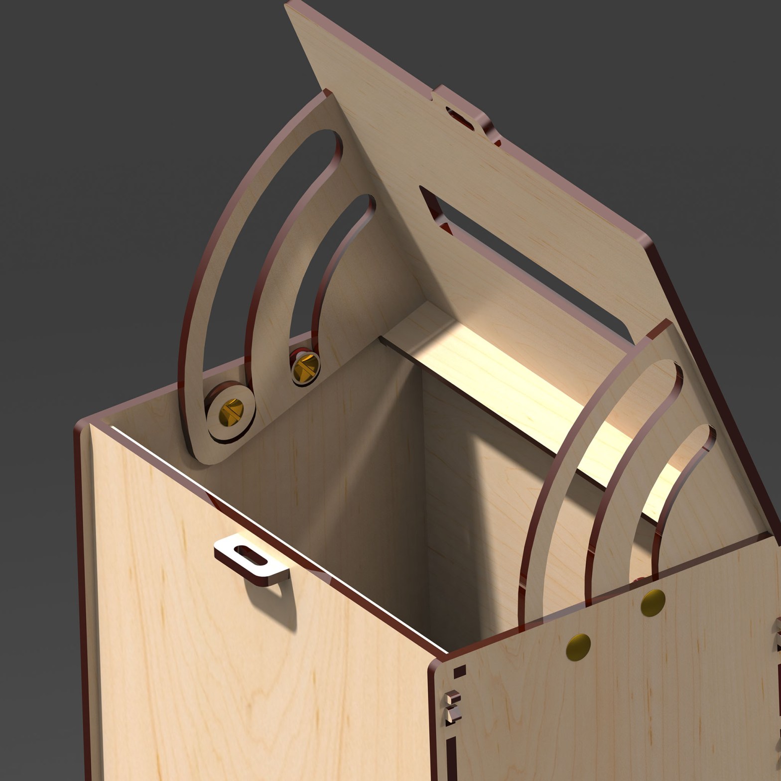
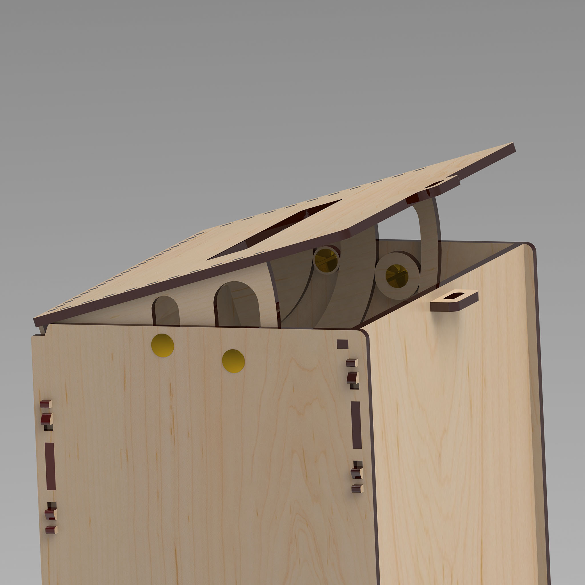
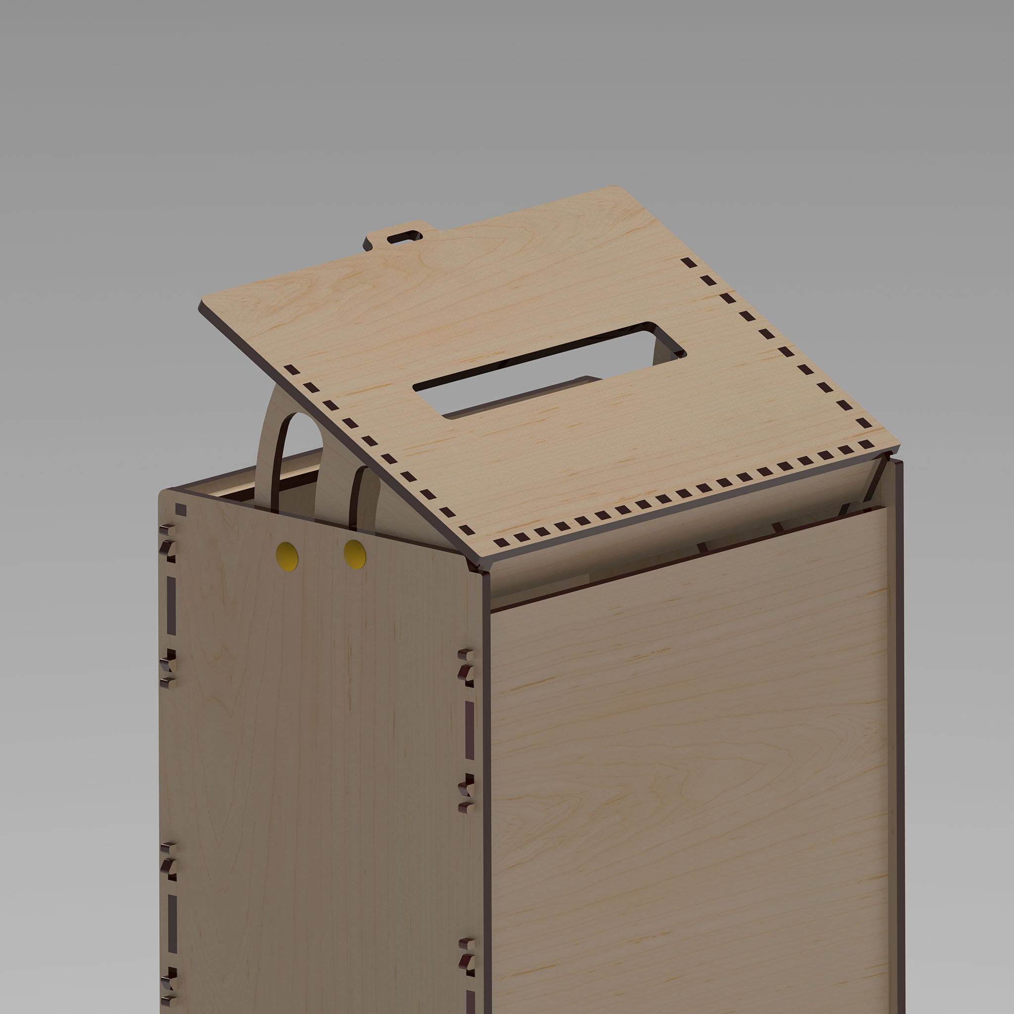
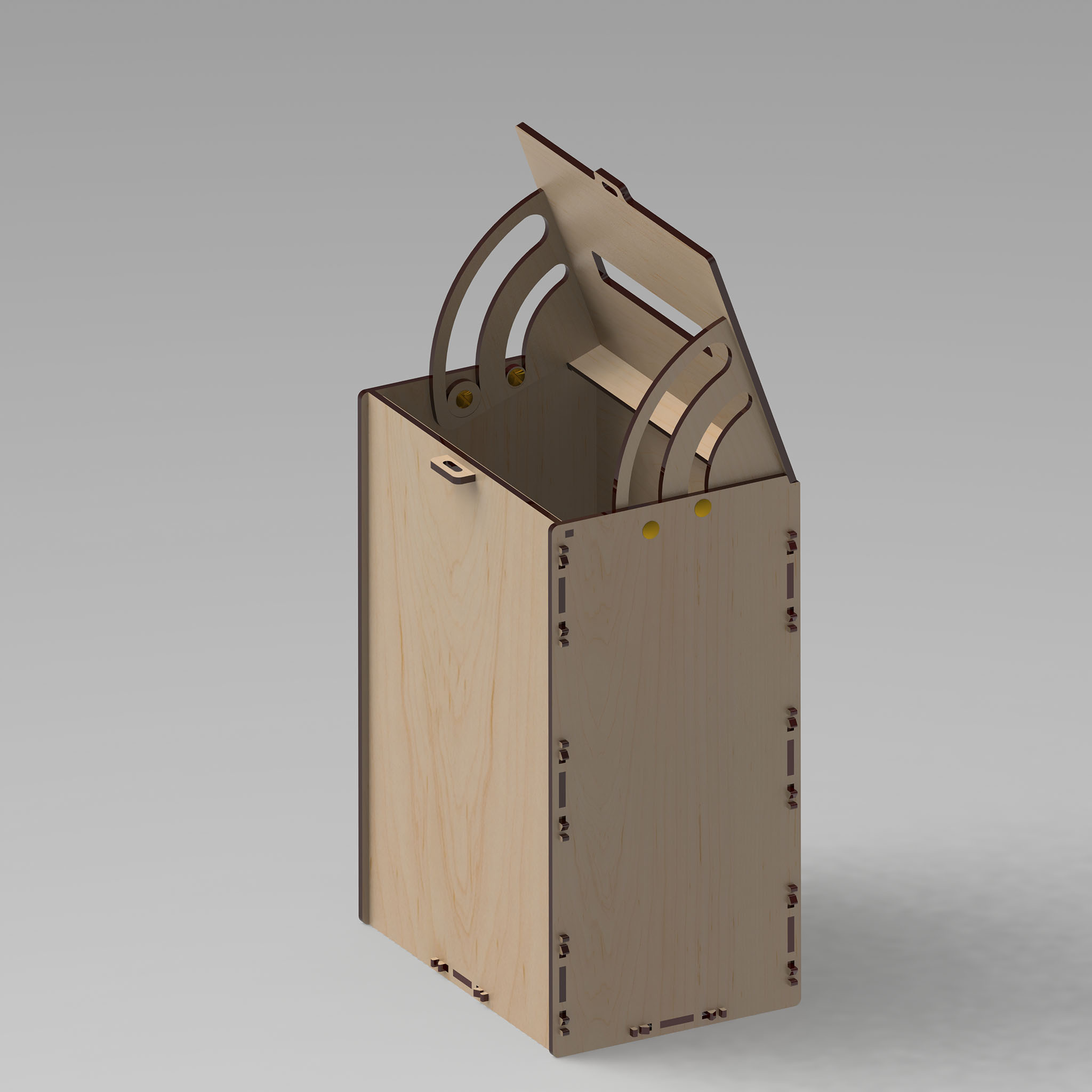
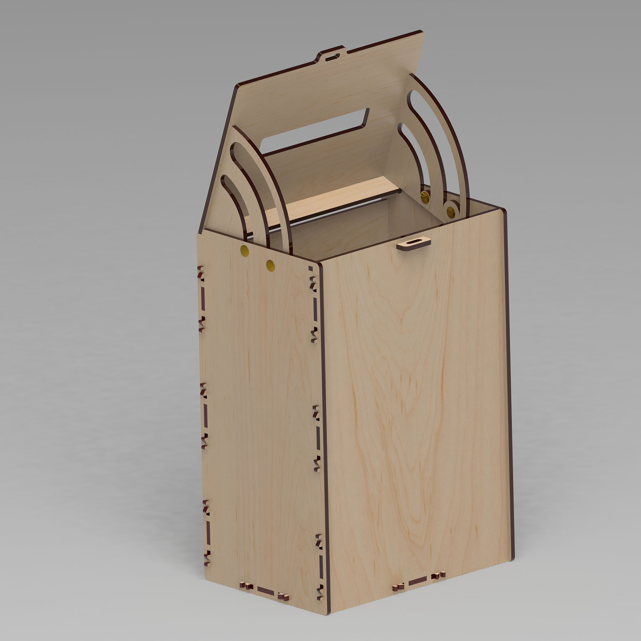
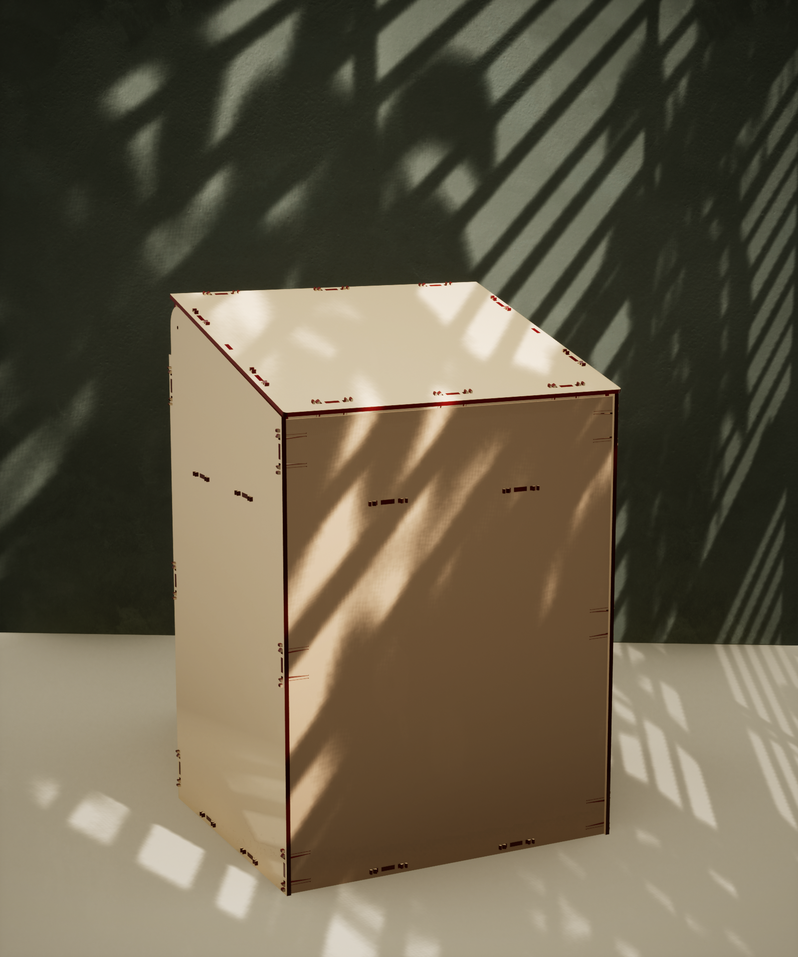
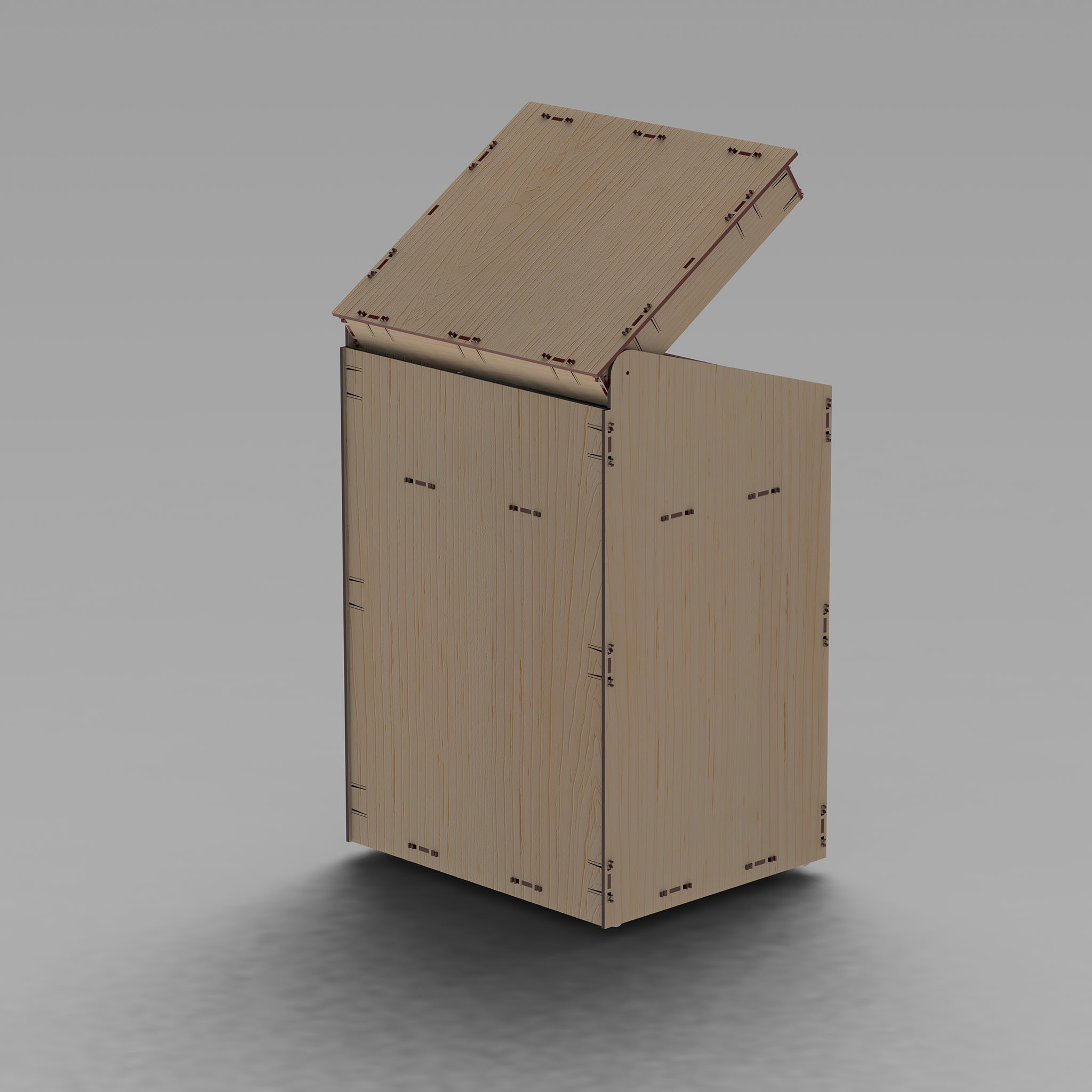
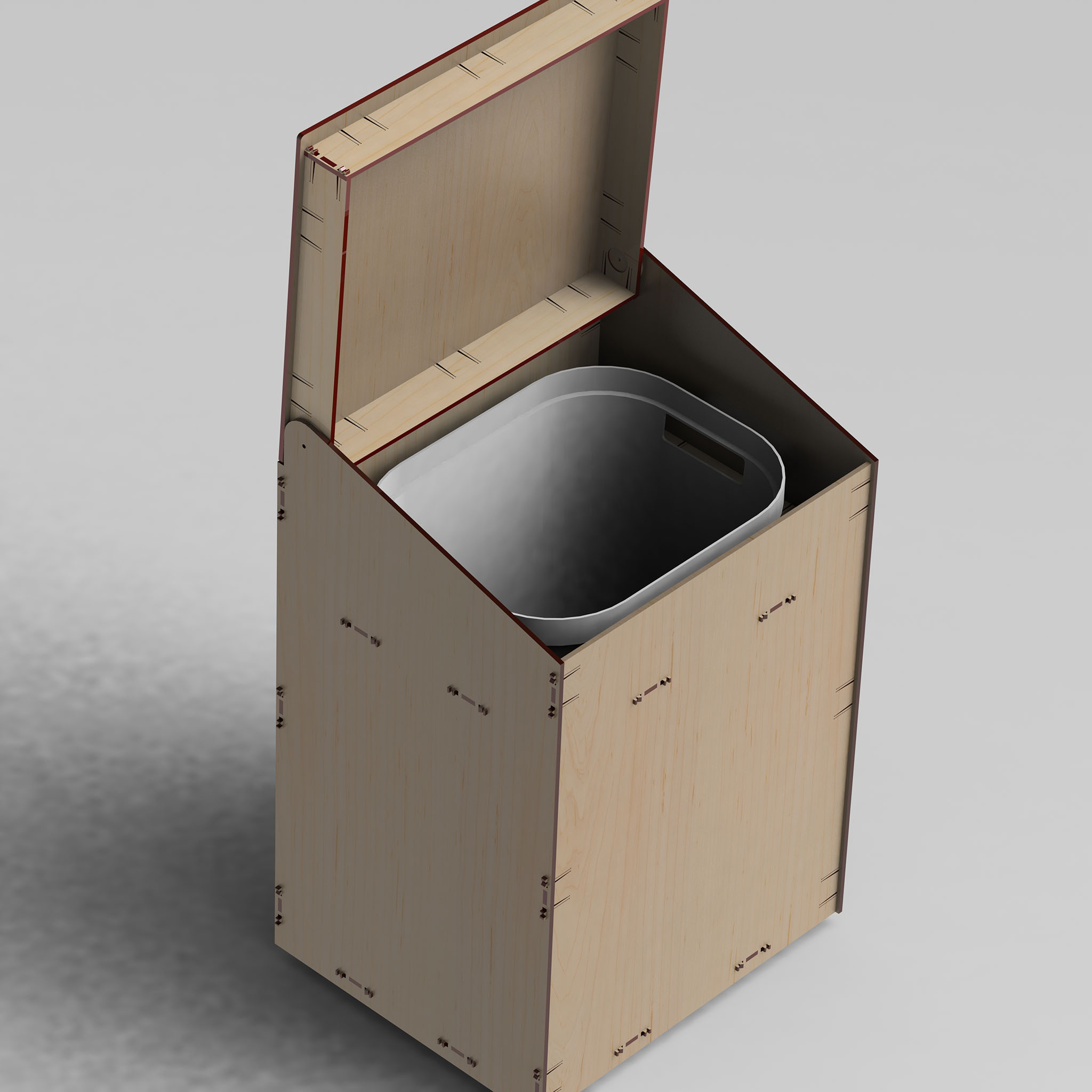
The material is 4mm plywood.
![Laserl]ikus, Tauno Erik](https://taunoerik.art/wp-content/uploads/2023/06/wb01.jpg)
![Laserl]ikus, Tauno Erik](https://taunoerik.art/wp-content/uploads/2023/06/wb02.jpg)
![Laserl]ikus, Tauno Erik](https://taunoerik.art/wp-content/uploads/2023/06/wb03.jpg)
![Laserl]ikus, Tauno Erik](https://taunoerik.art/wp-content/uploads/2023/06/wb04.jpg)

Oil on canvas, 50×60 cm.