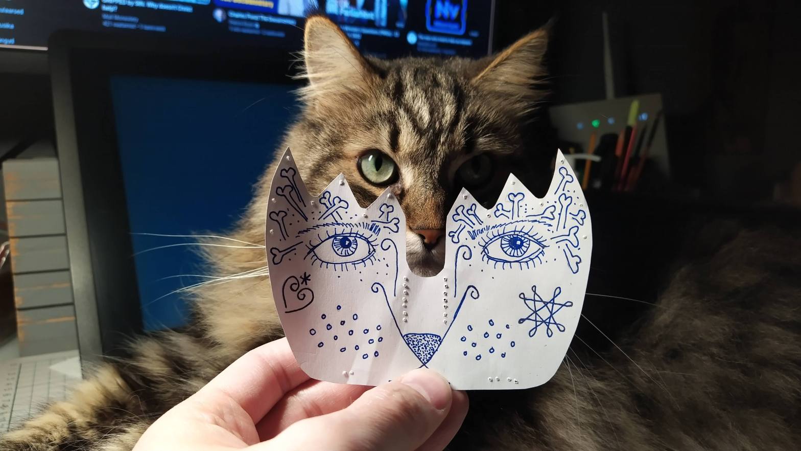
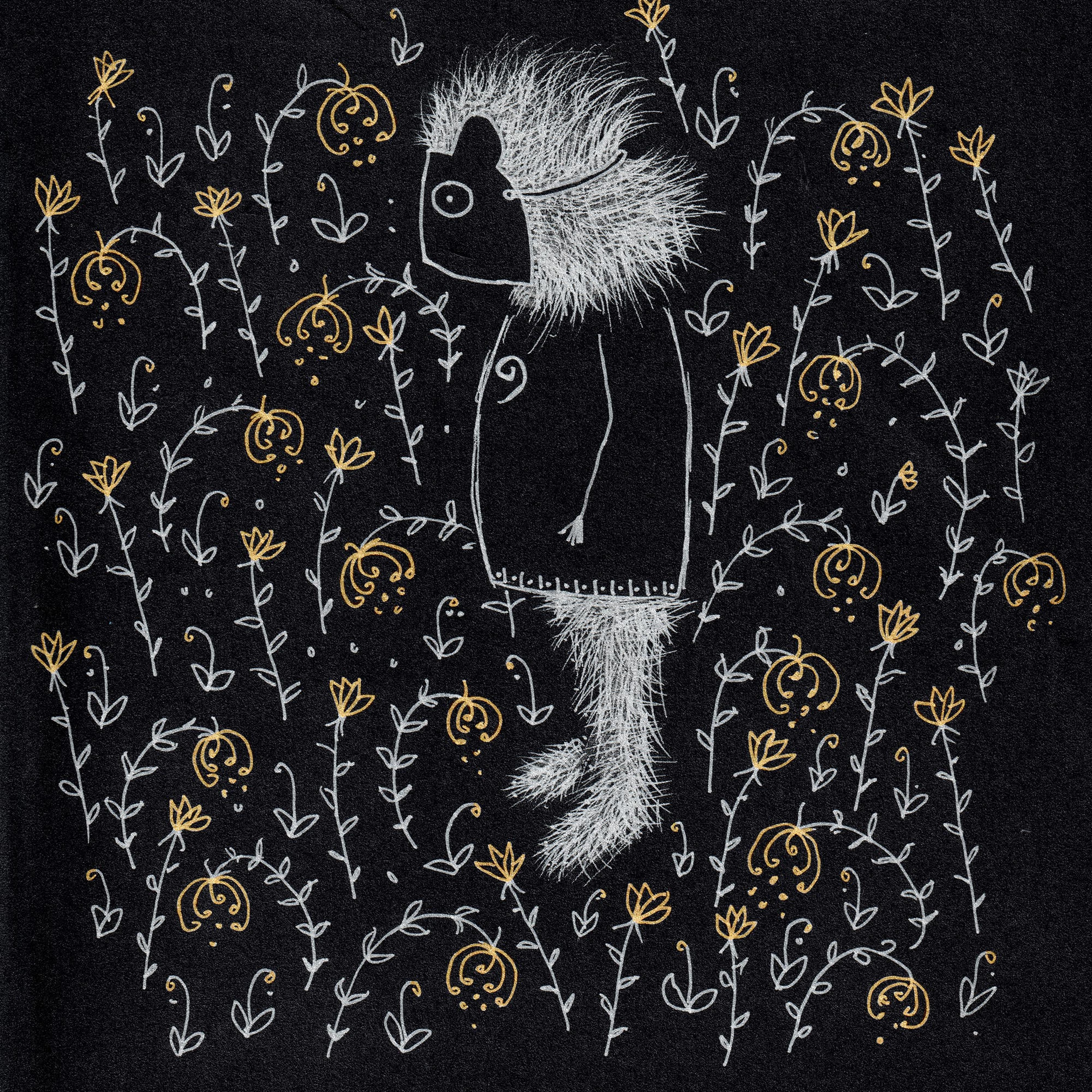
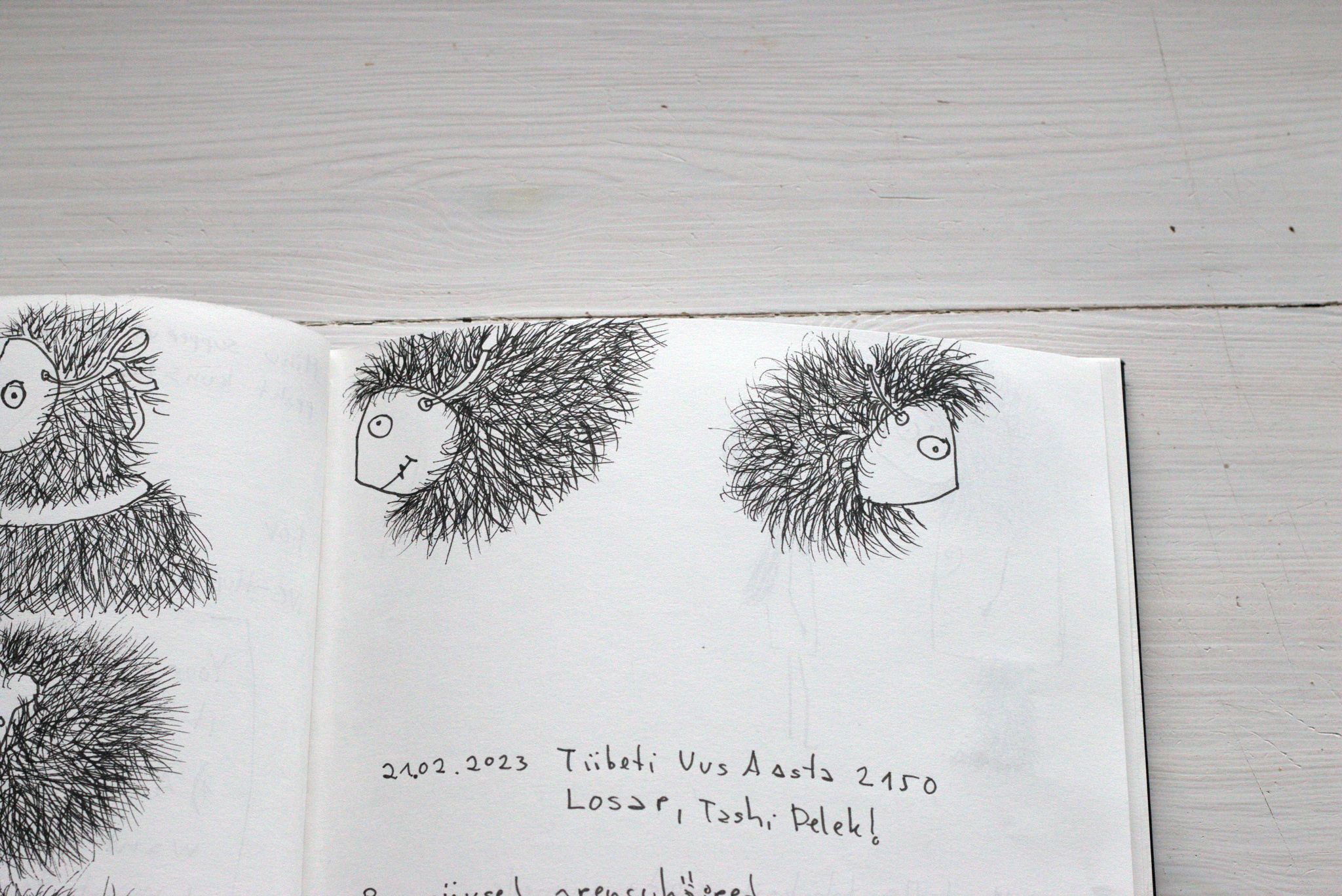
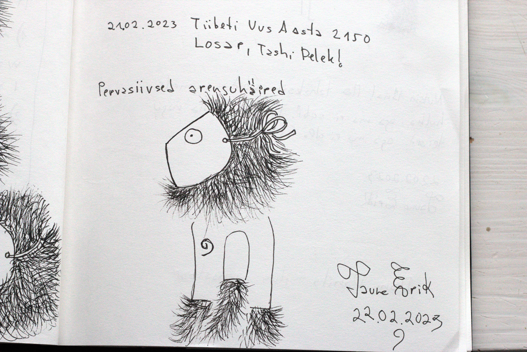
The world is full of signs. Here are some of the cryptic signs from my inner world.
Gouache on paper.
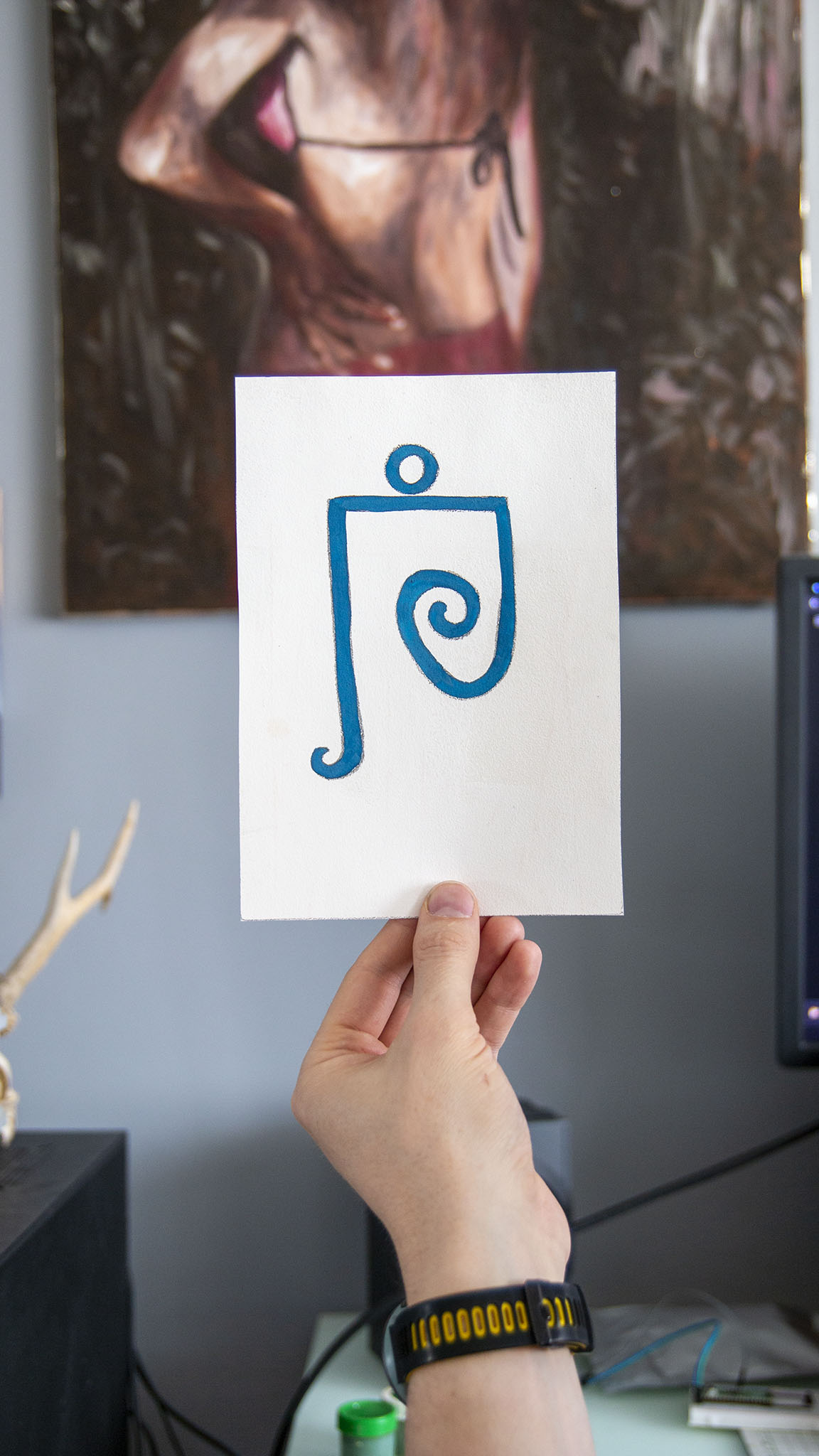
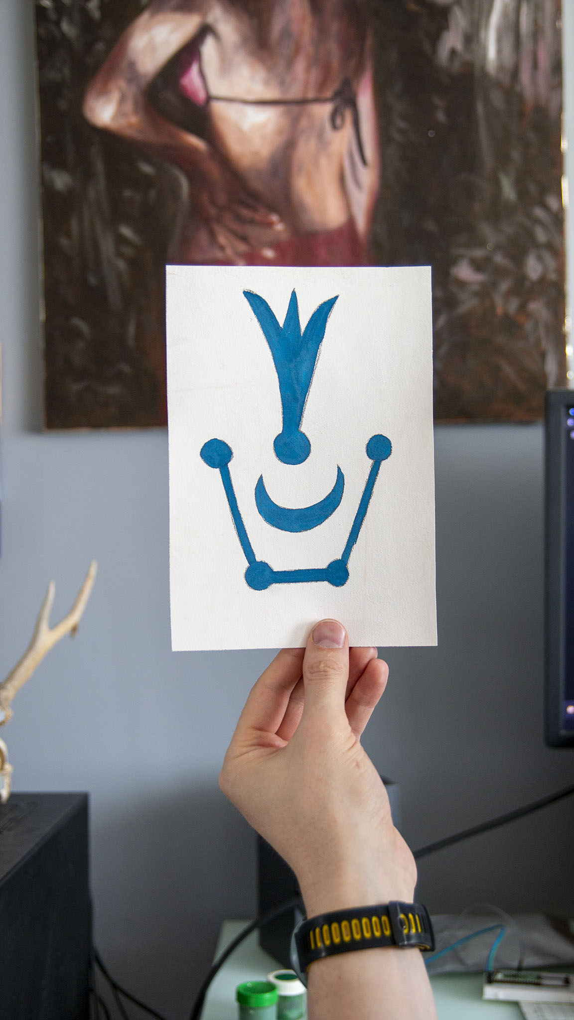
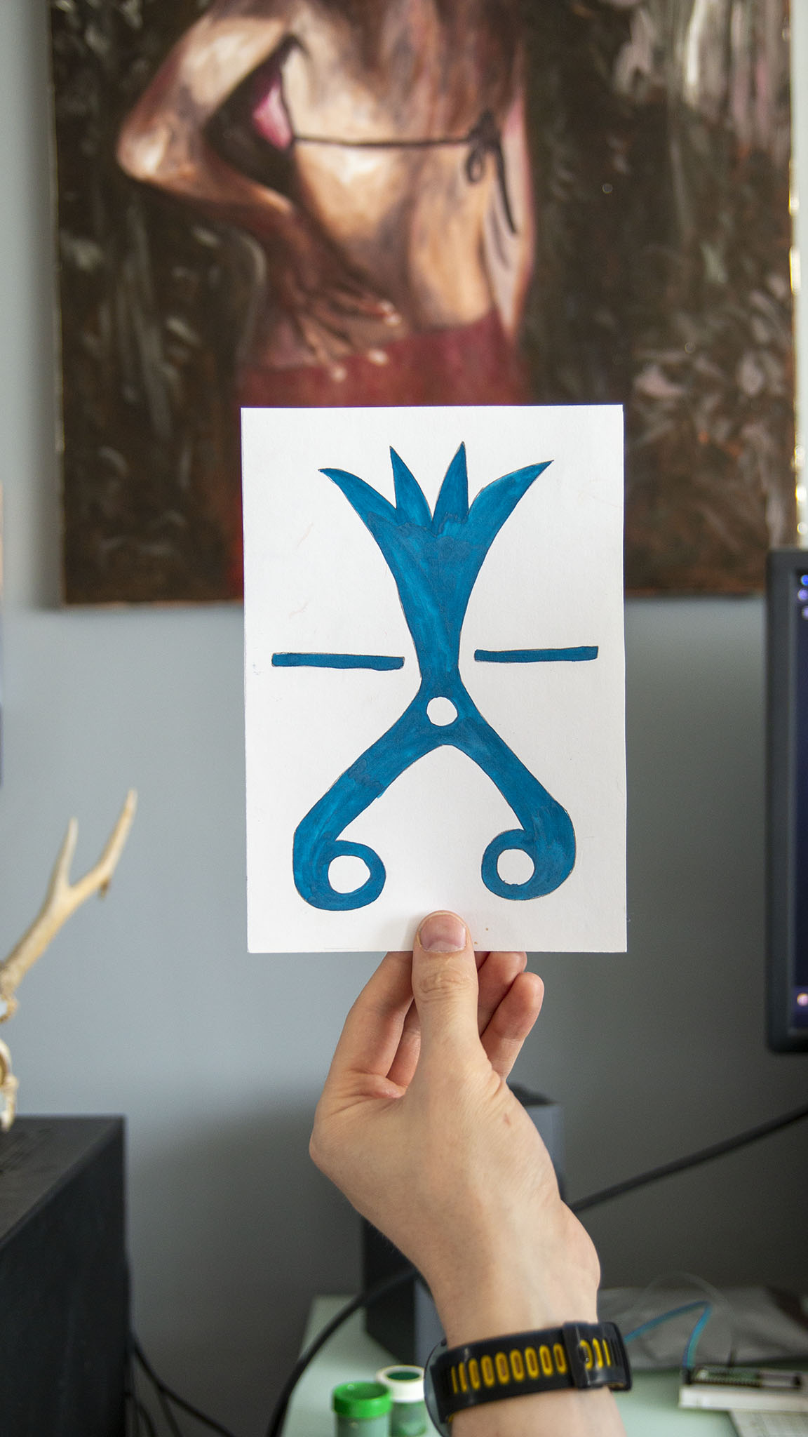
And one earlier experiment:
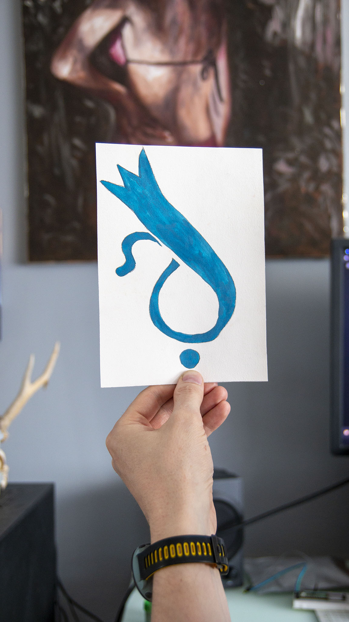
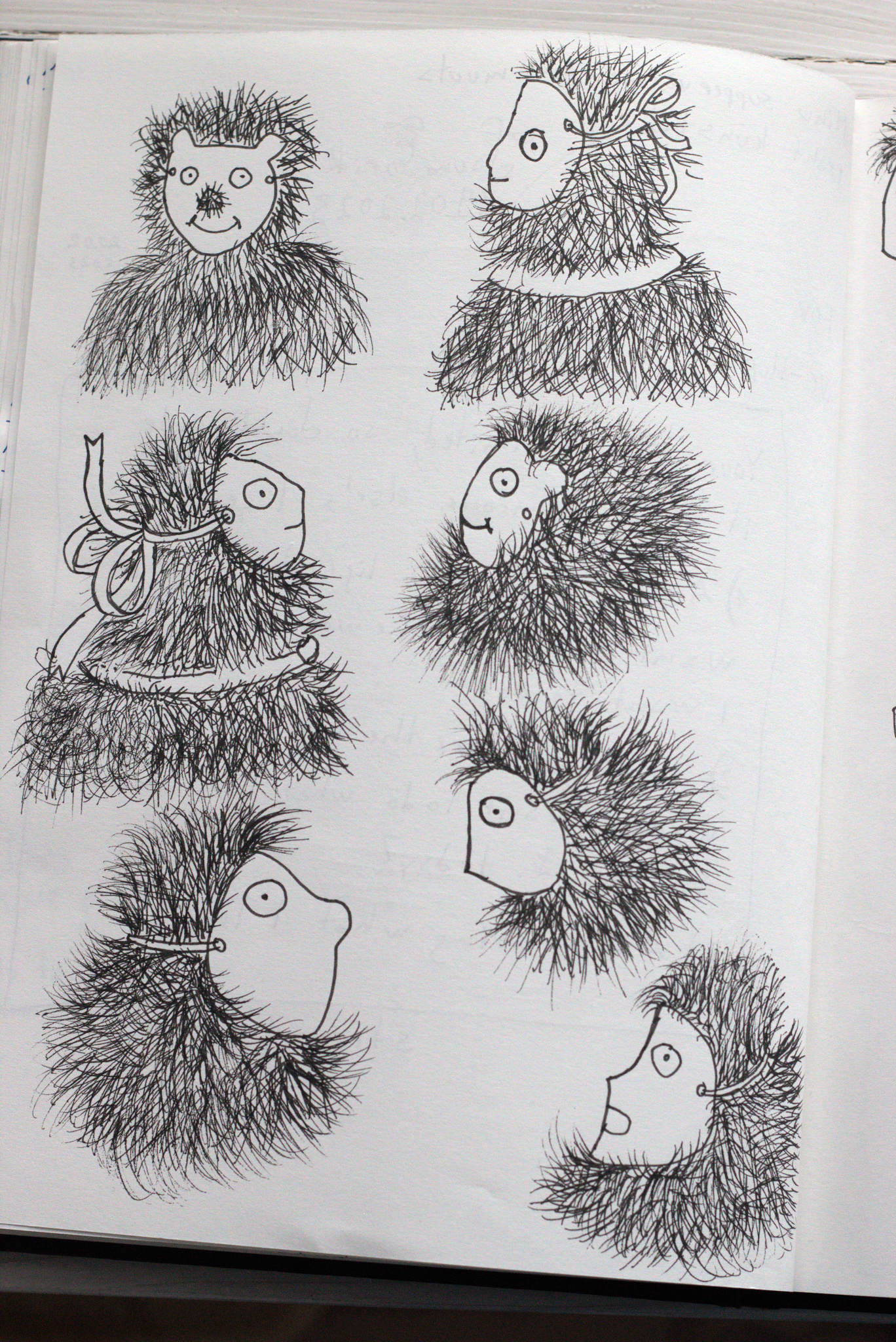
The world is full of signs. Here are some of the cryptic signs from my inner world.
Gouache on paper.
And one earlier experiment:

Here are my two short stop-motion animations with PCB.
Recently I have used a lot of The Dave Brubeck Quartet music. Especially the Take Five. I think the live video from 1964 is especially cool. And I used some AI programs to upscale it. It took around 10 hours and turned my computer really hot. GPU temperature was 80C all the time and it made me very nervous.
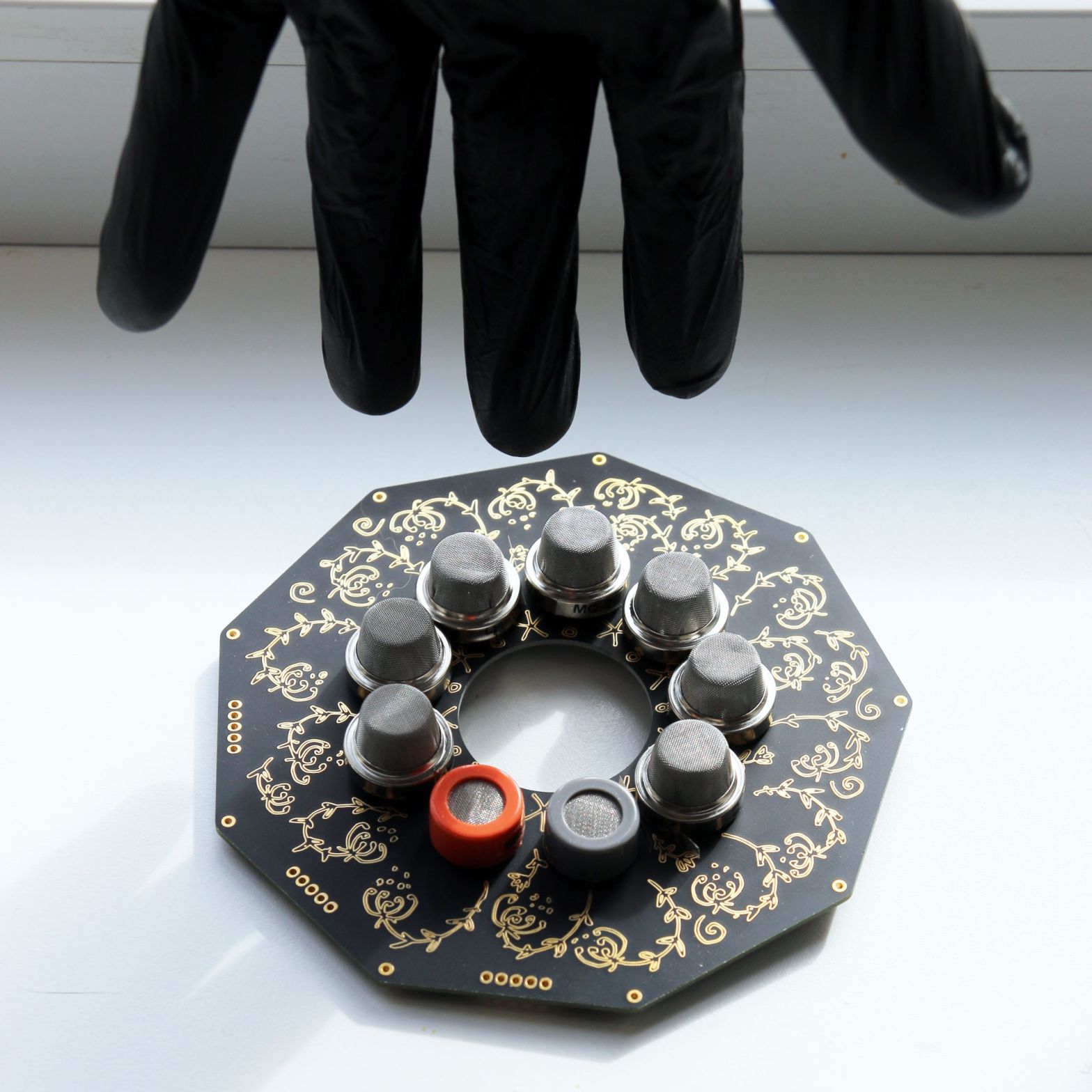
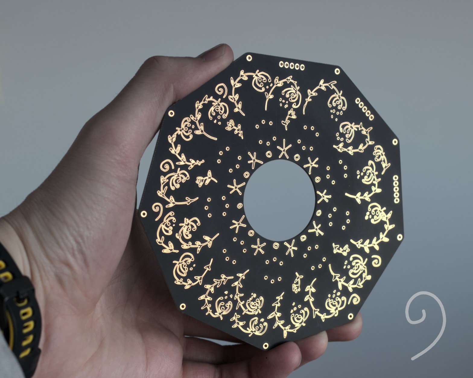
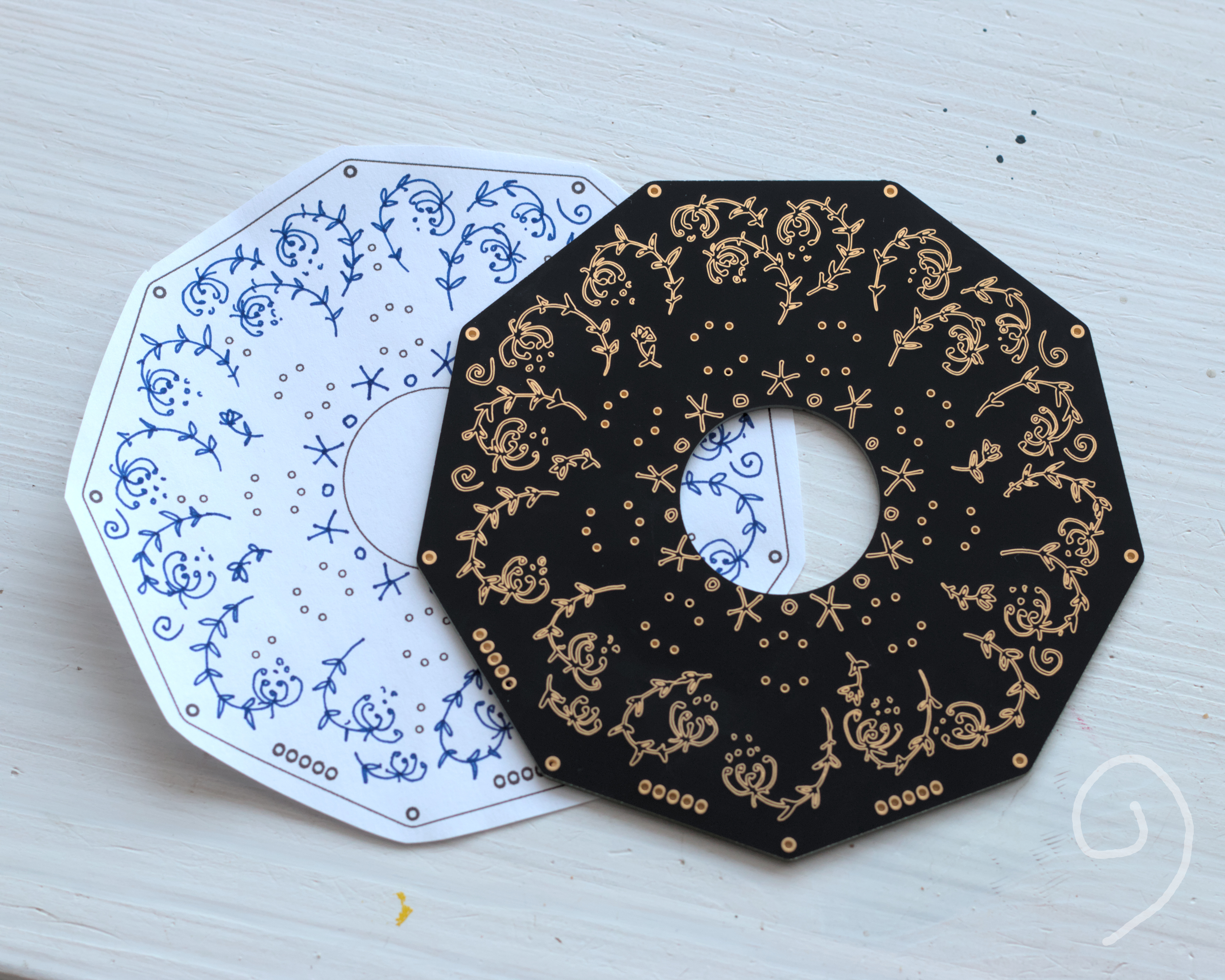
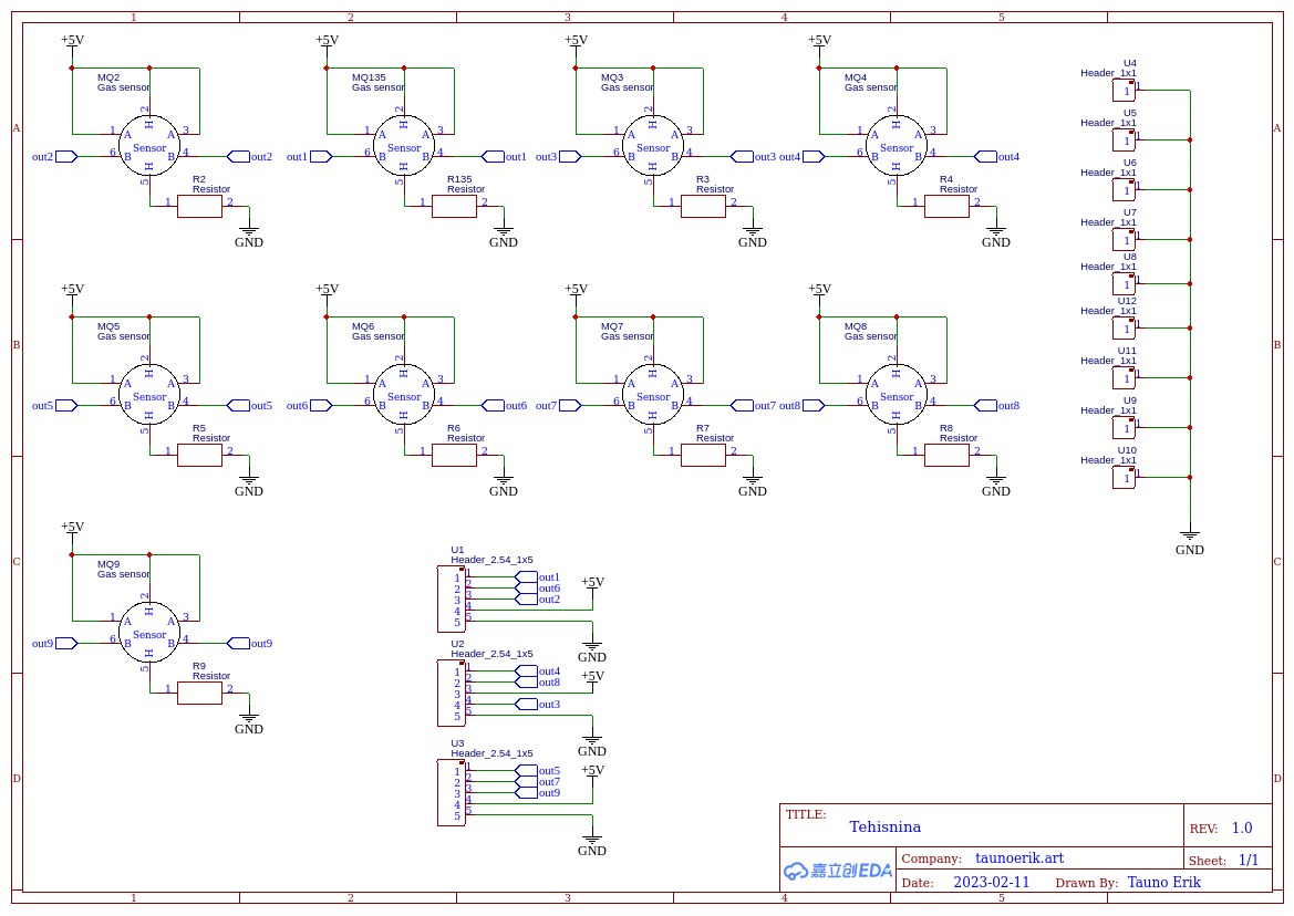
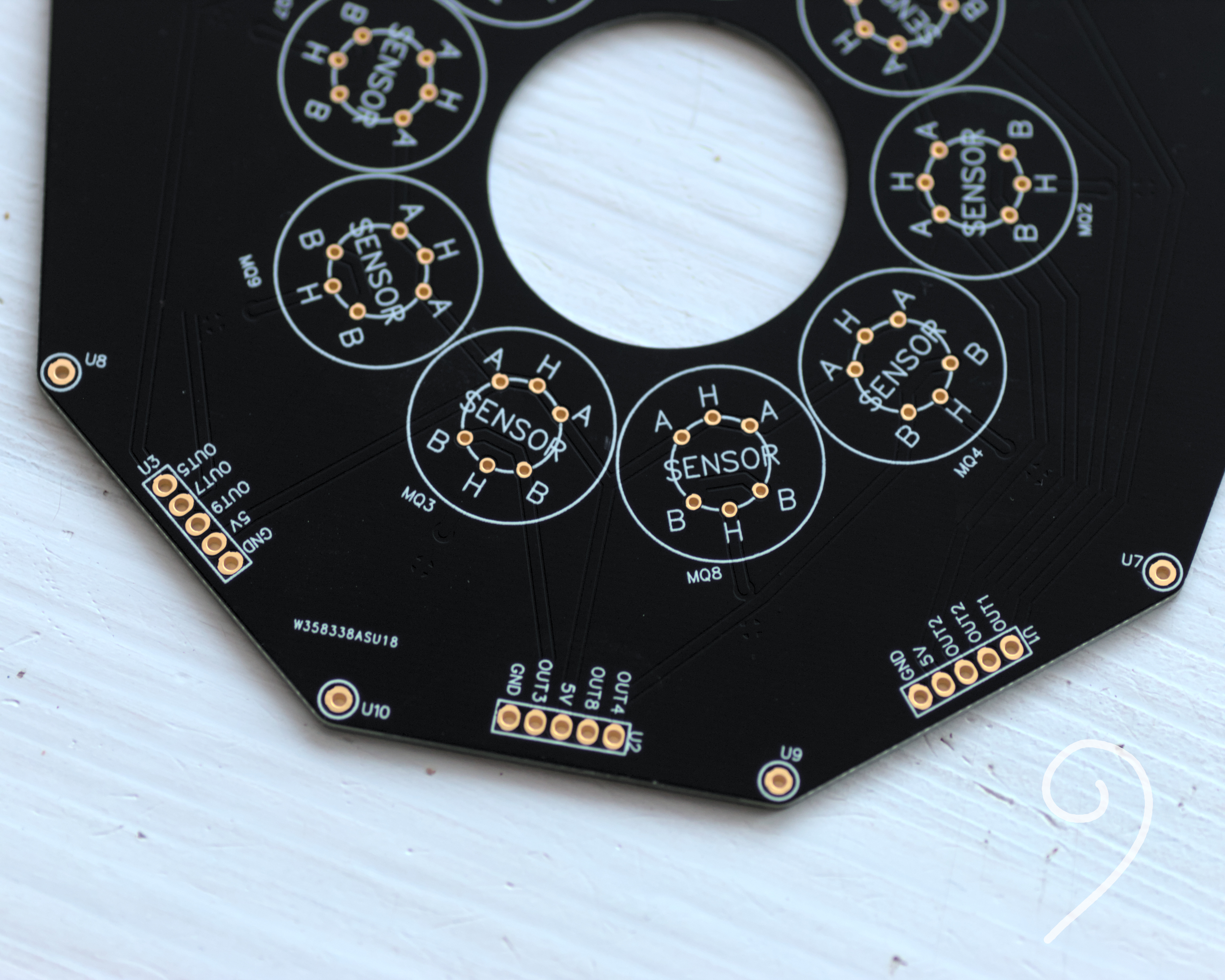
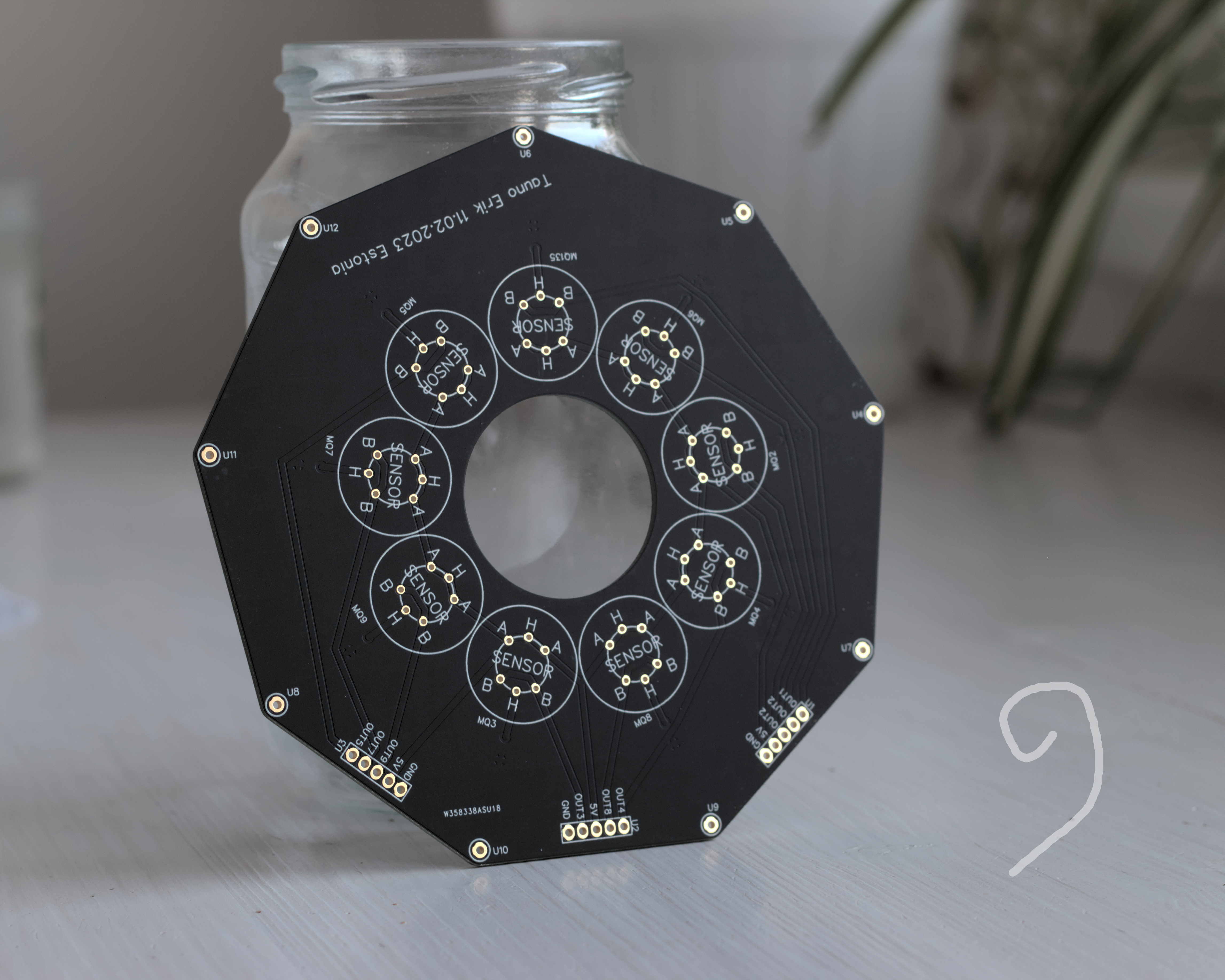
This is my new nine-cornered MCB. I plan to add nine gas sensors onto this board. It would be my artificial nose experiment.
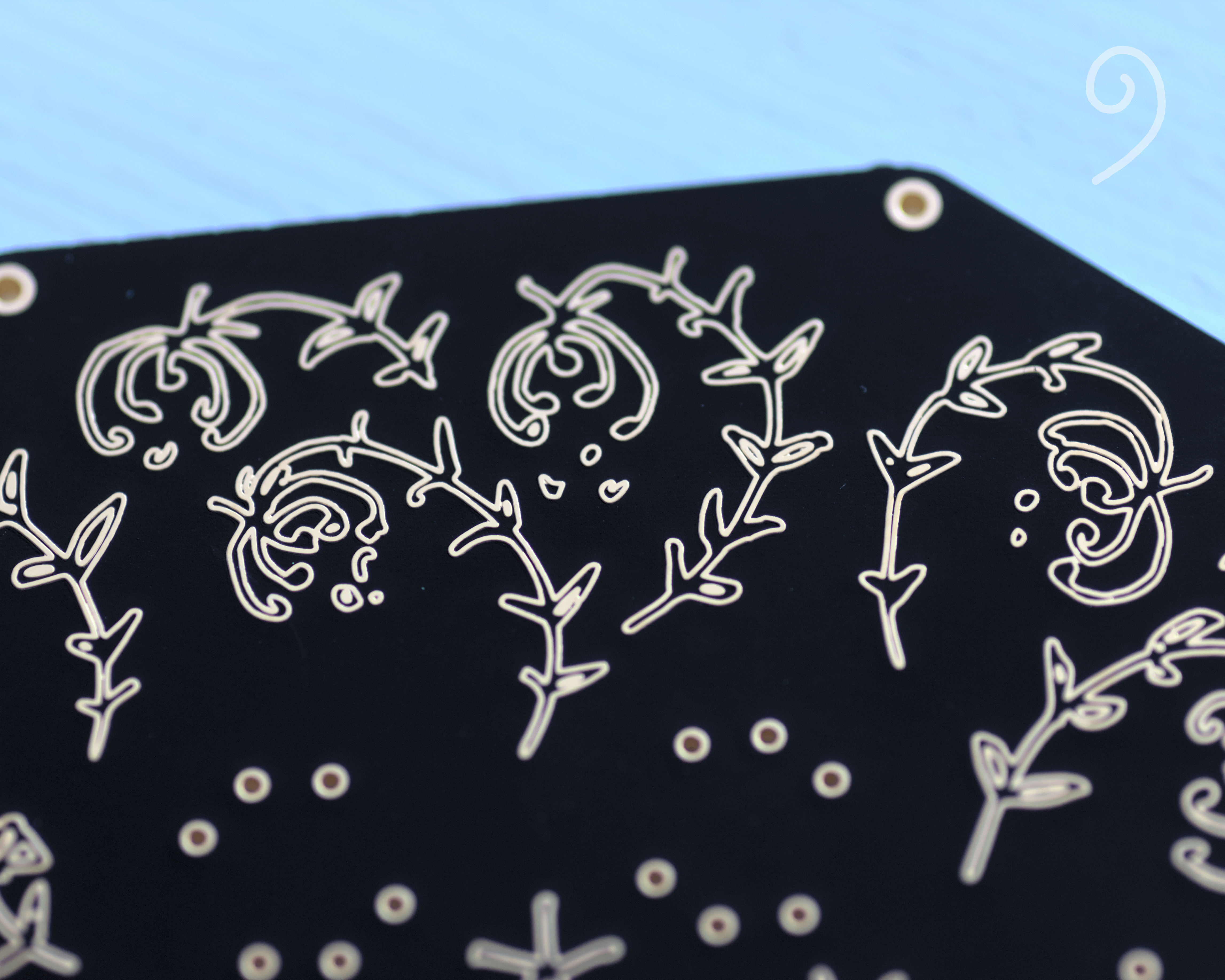
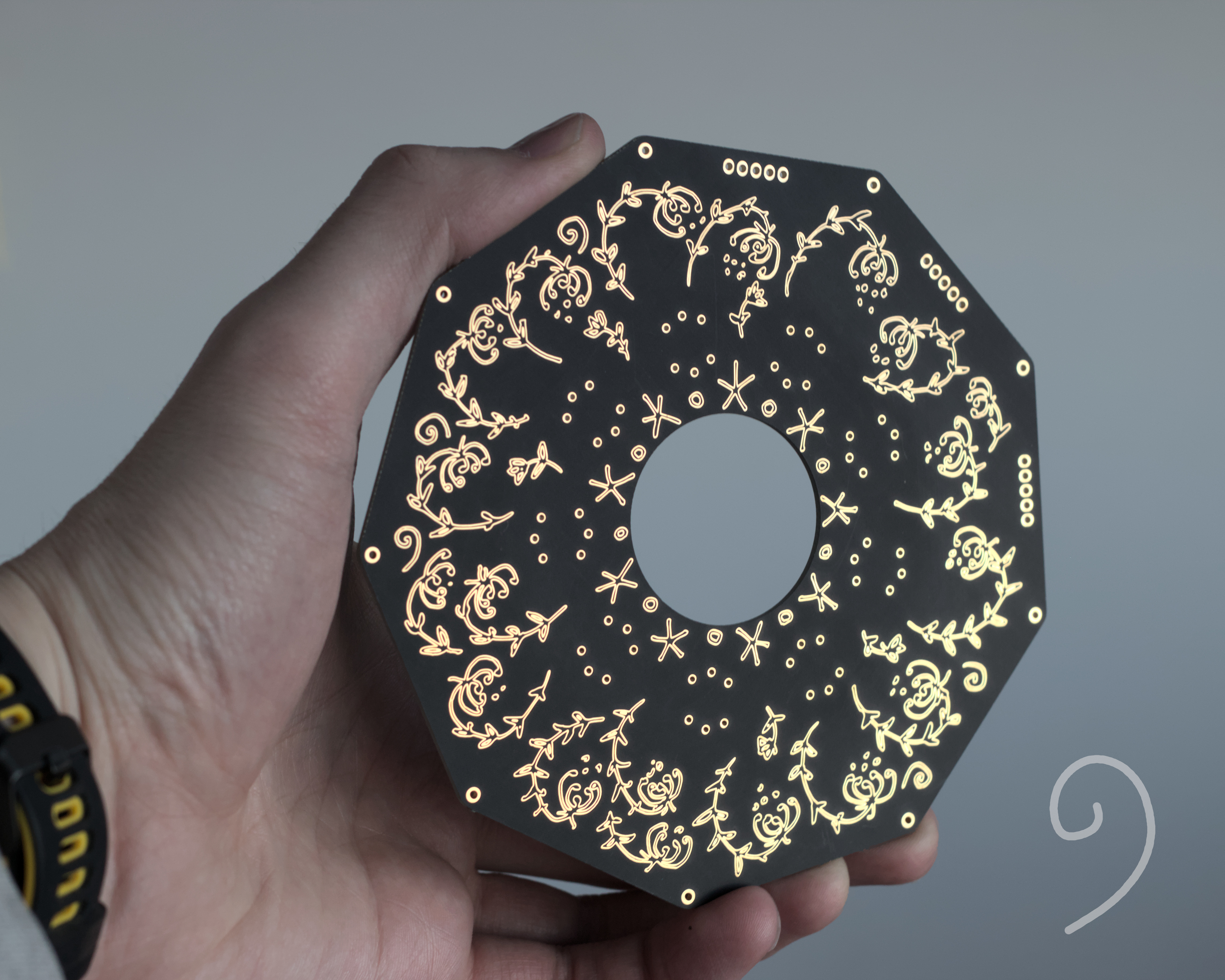
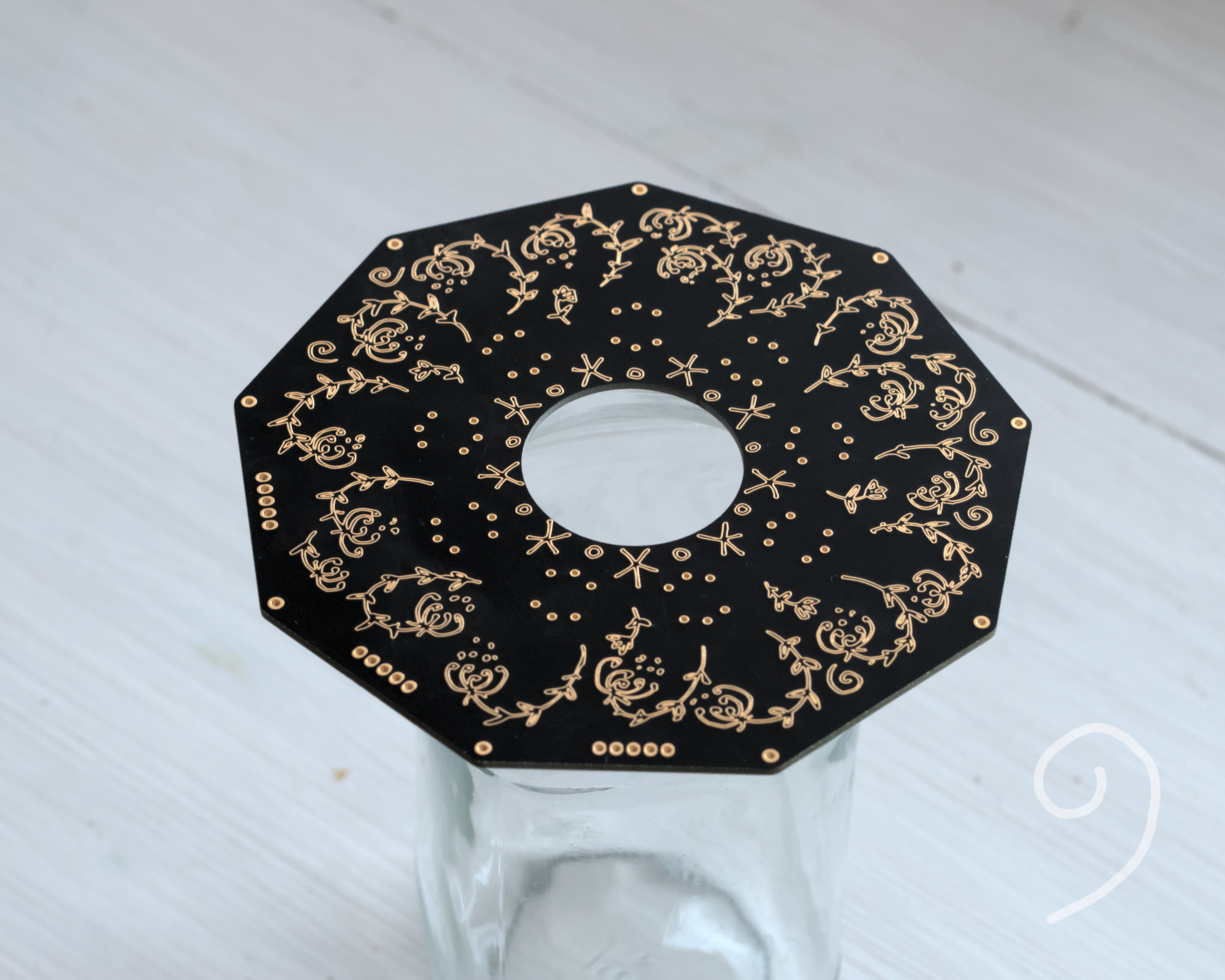
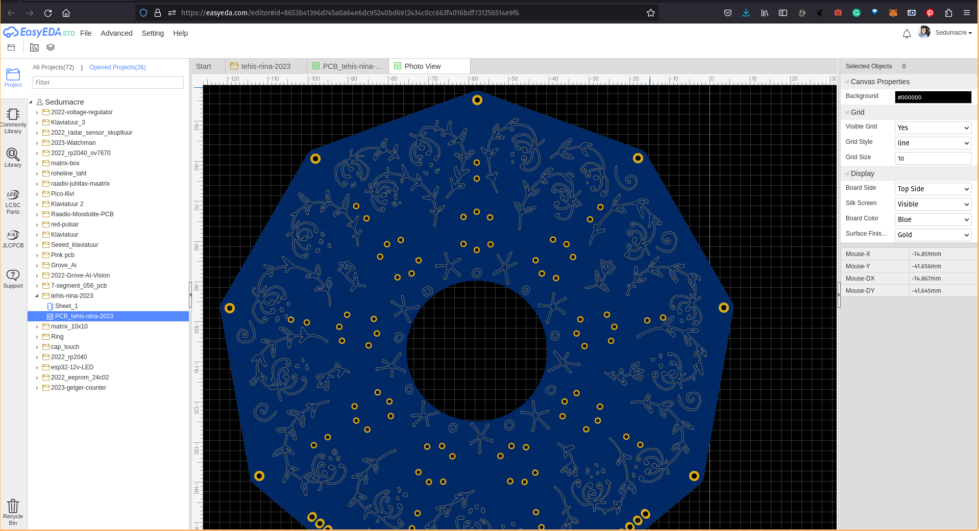
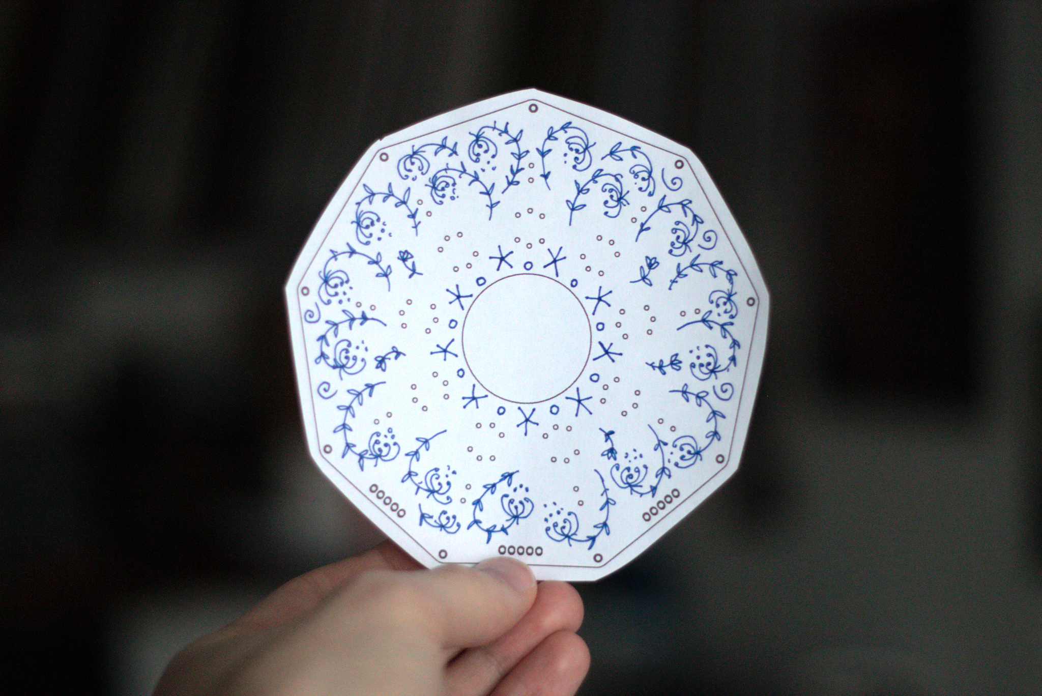
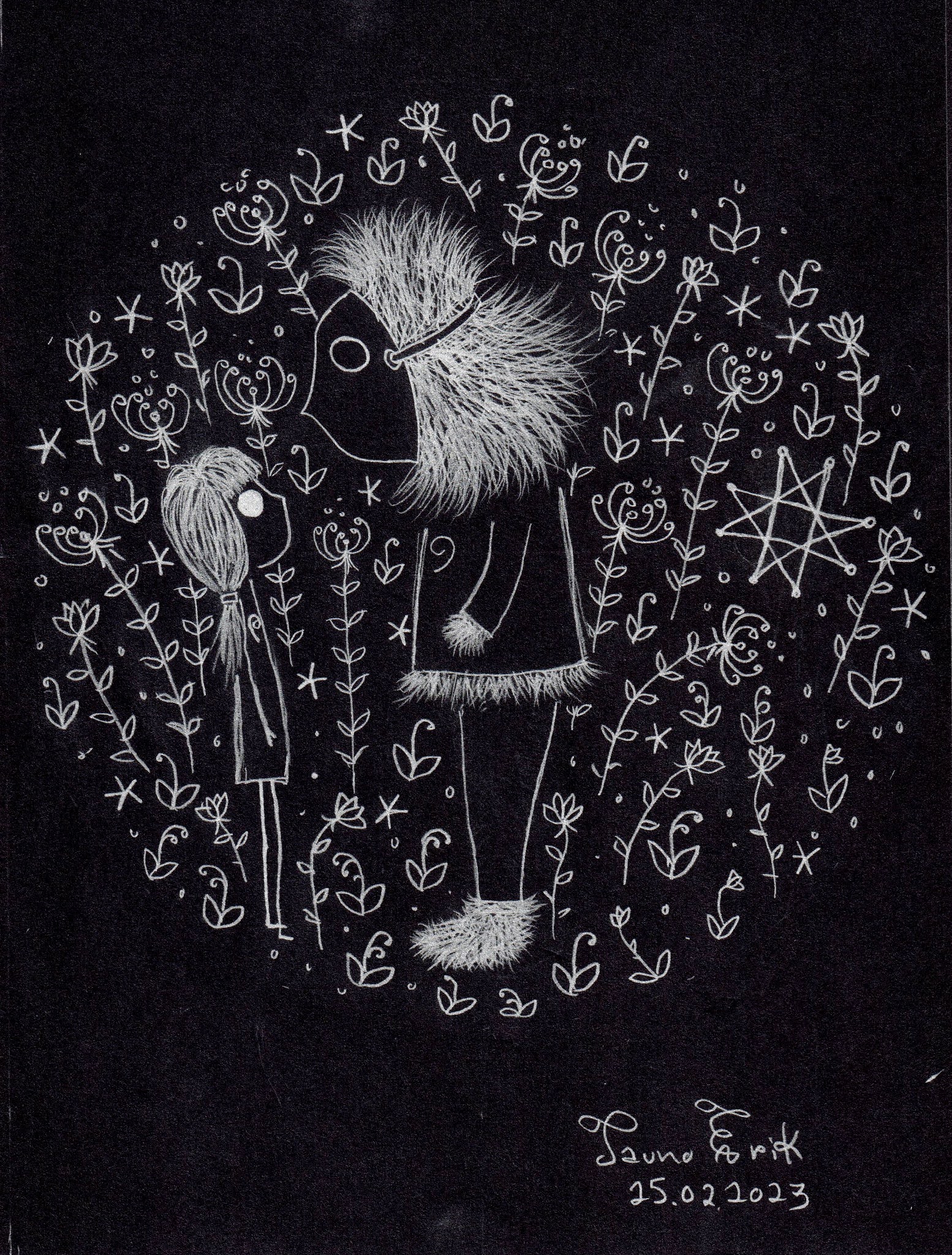
The flowers are hand drawn and vectorized.
It is made by PCBWay. It’s the first time when I ordered matte black coloured boards. And I really like that it makes it feel deeper and darker than the shiny one would be.
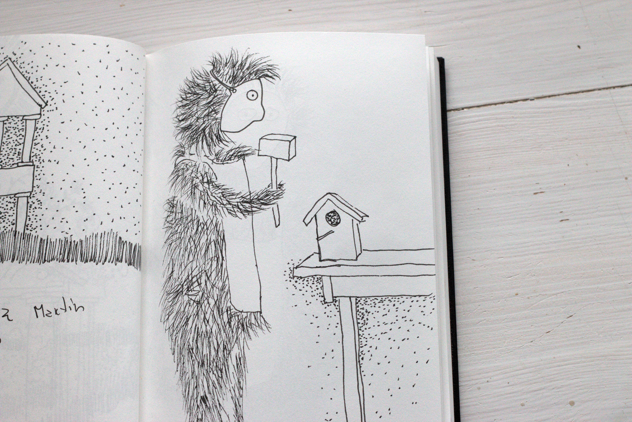
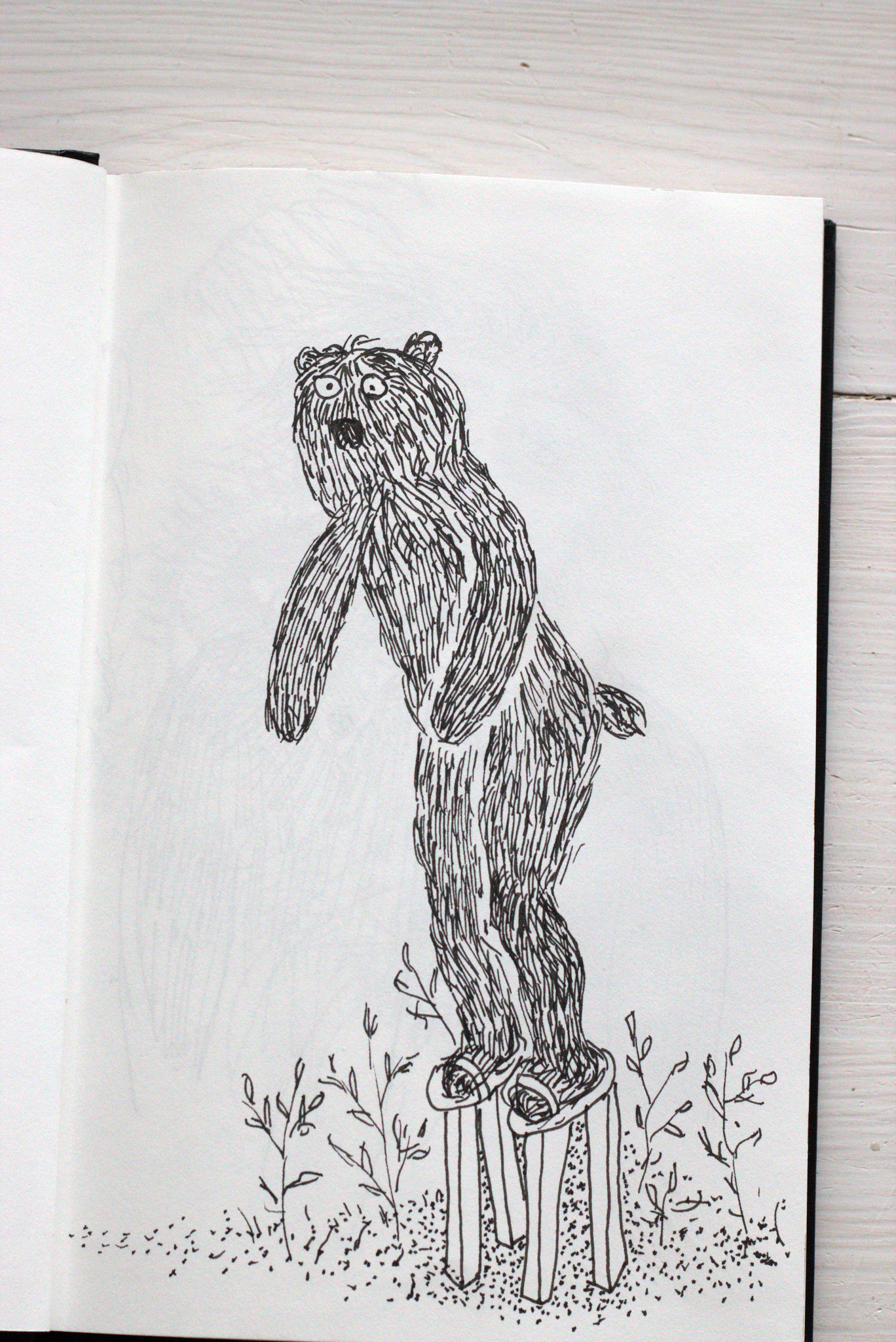
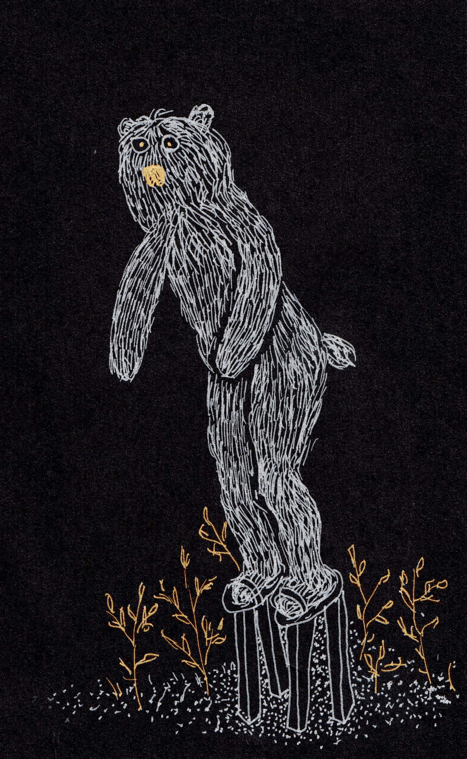
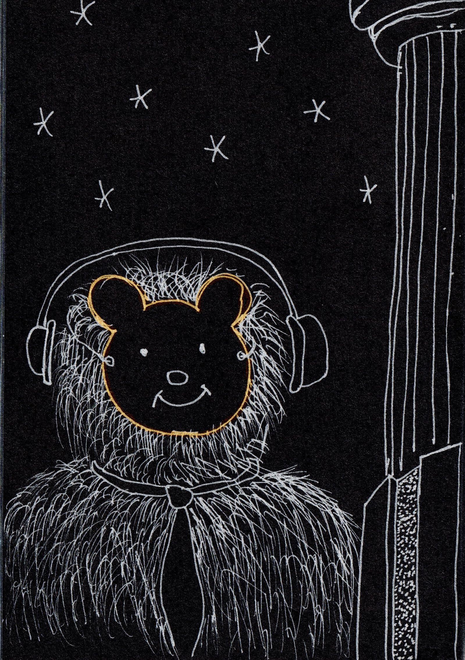
This is a new character I have started to draw recently. He started first as a bear. Then began to wear a mask. And now I think that he is Yeti, Bigfoot, Snowman or ten more different names how he is called. He is wearing a mask because no one really knows who he is. And he is also missing, you haven’t found him yet.


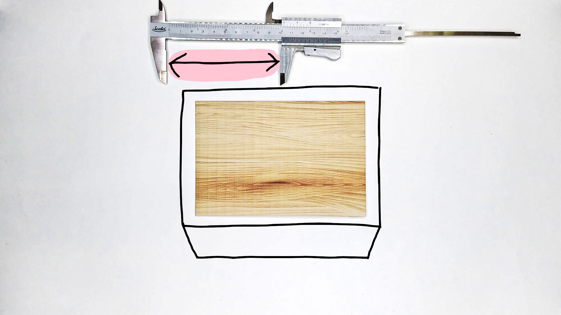
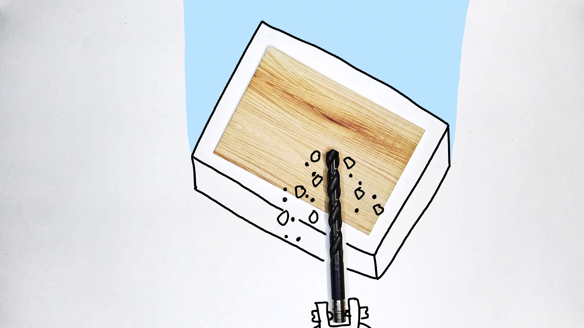
I had this, not working, ceiling lamp that collected dust. And I was wondering what to do with it and I found a way how to turn it into artwork.
And it’s relatively easy to do if you have access to some technologies like laser cutting and printing. The picture is printed under plexiglass.
I use one of my drawings. You can find the rest on Instagram or here.
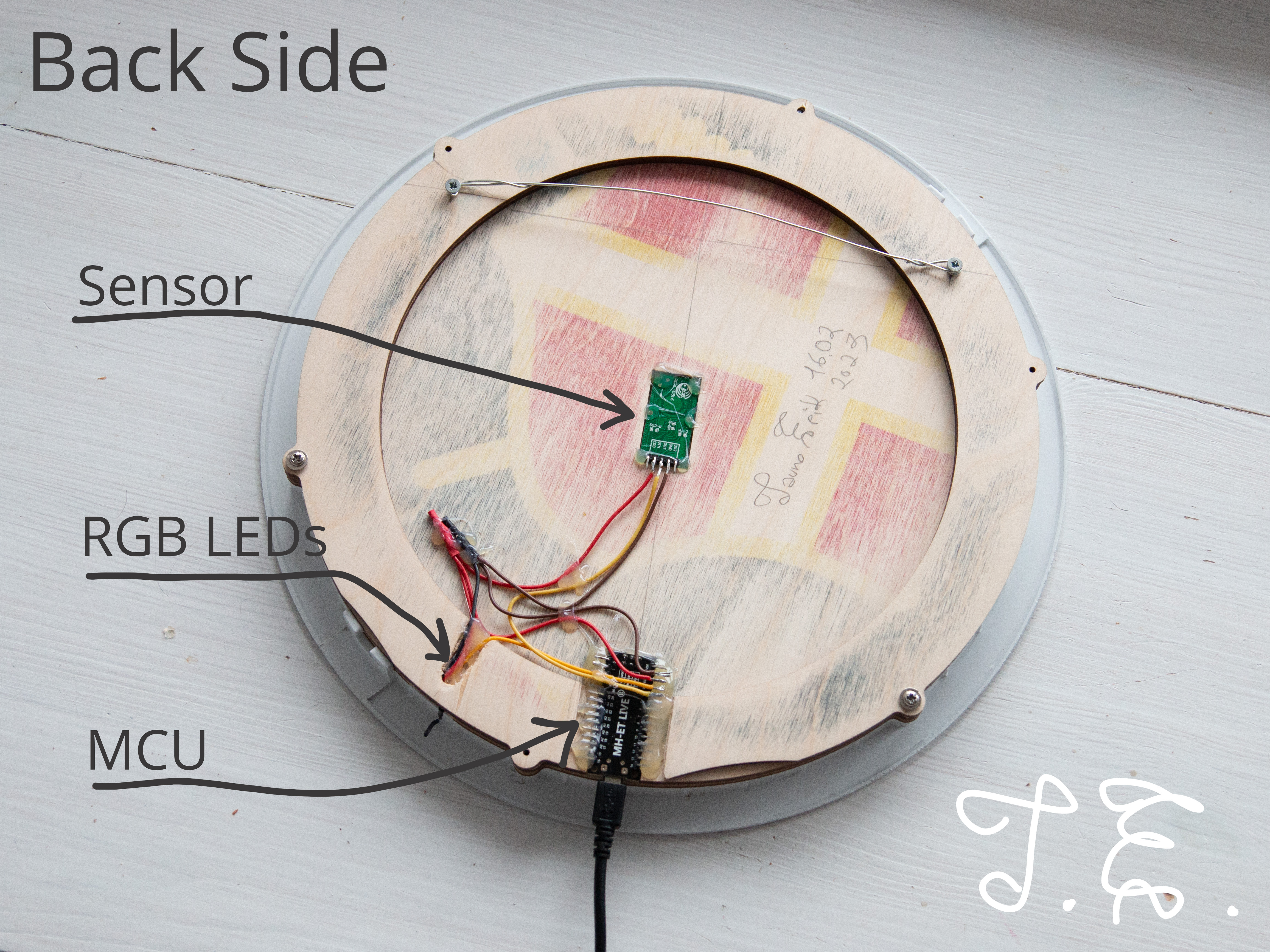
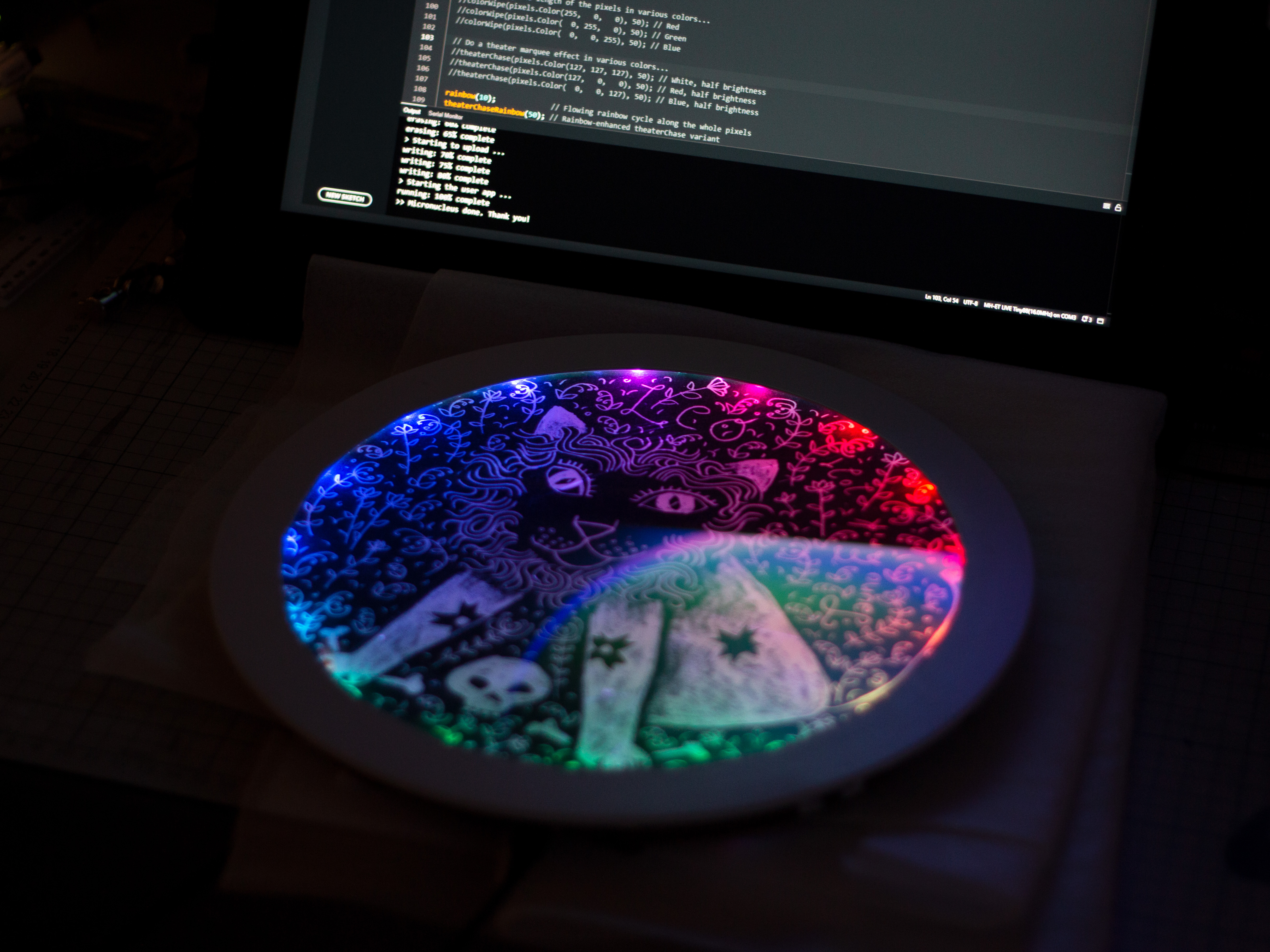
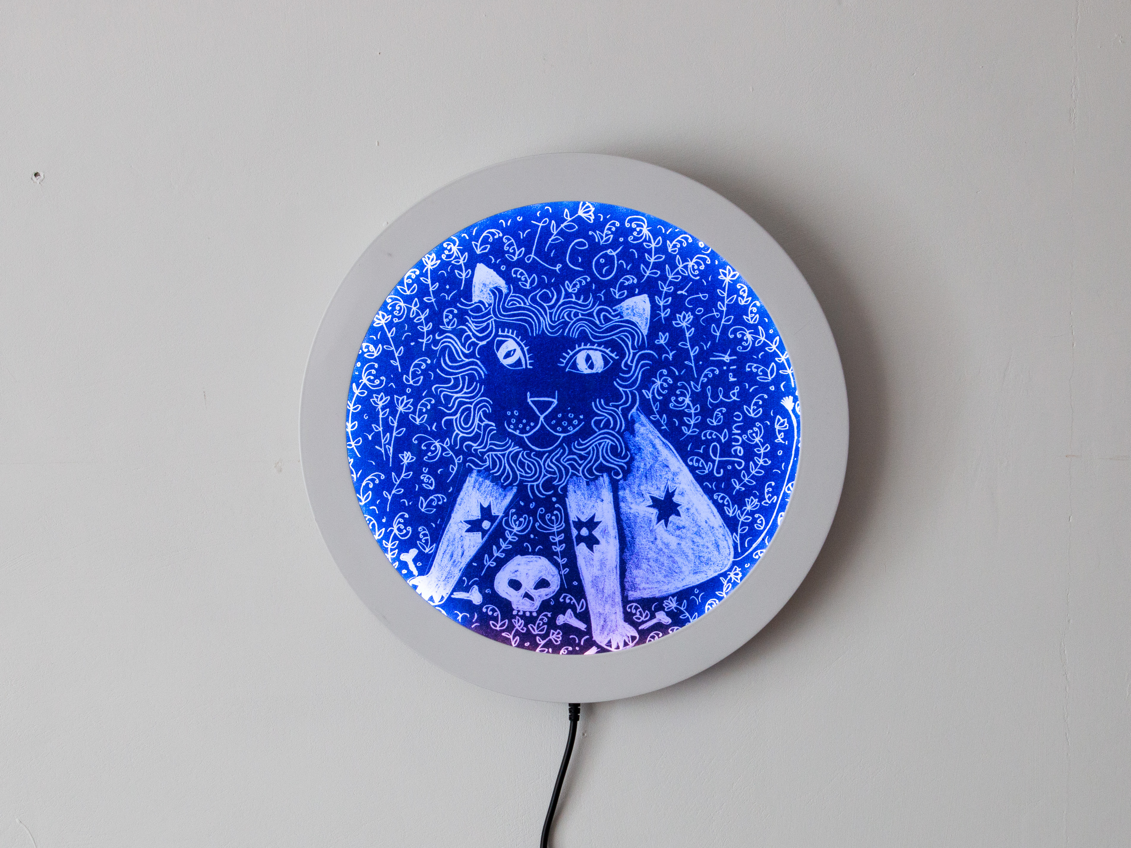
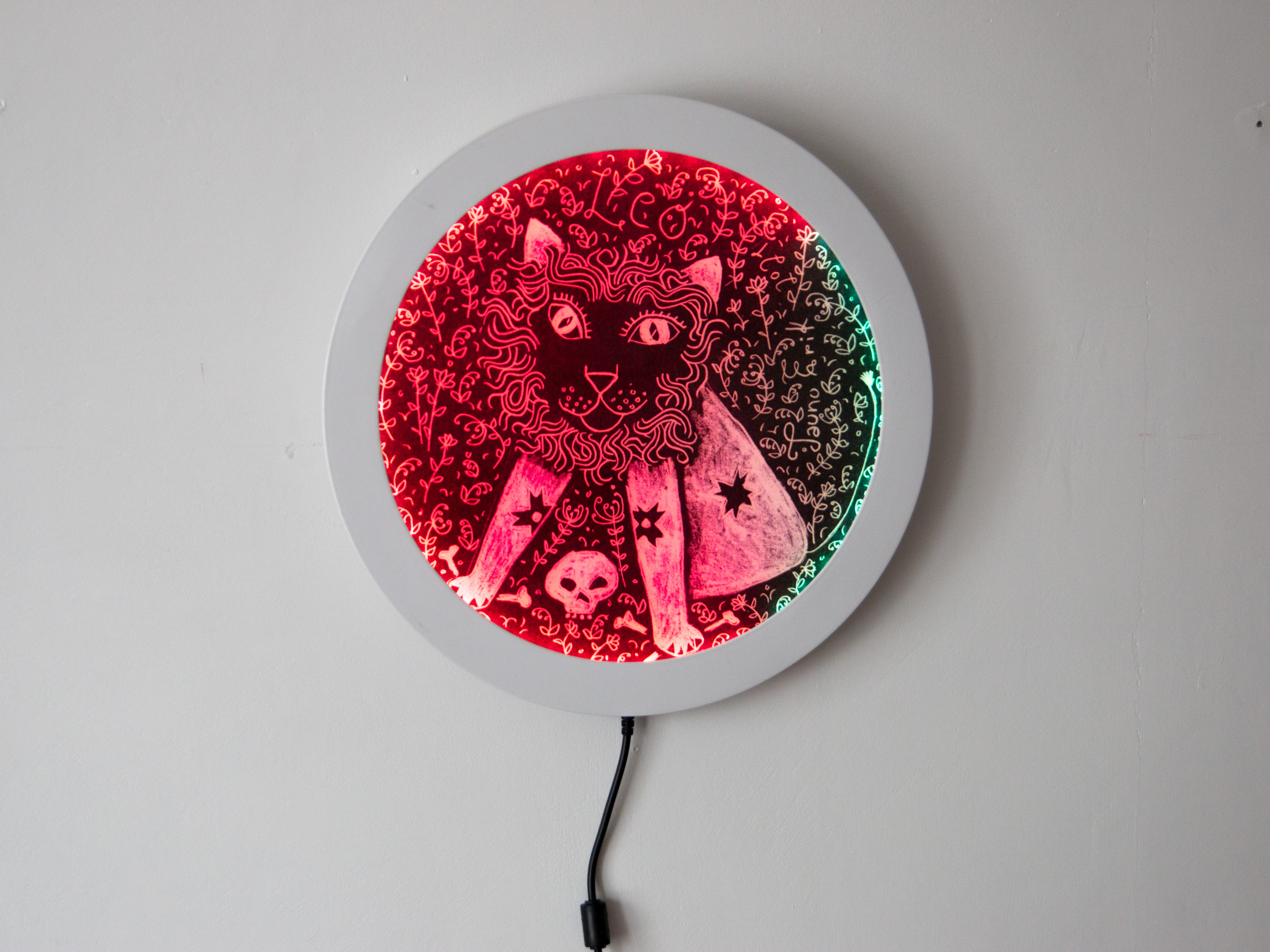
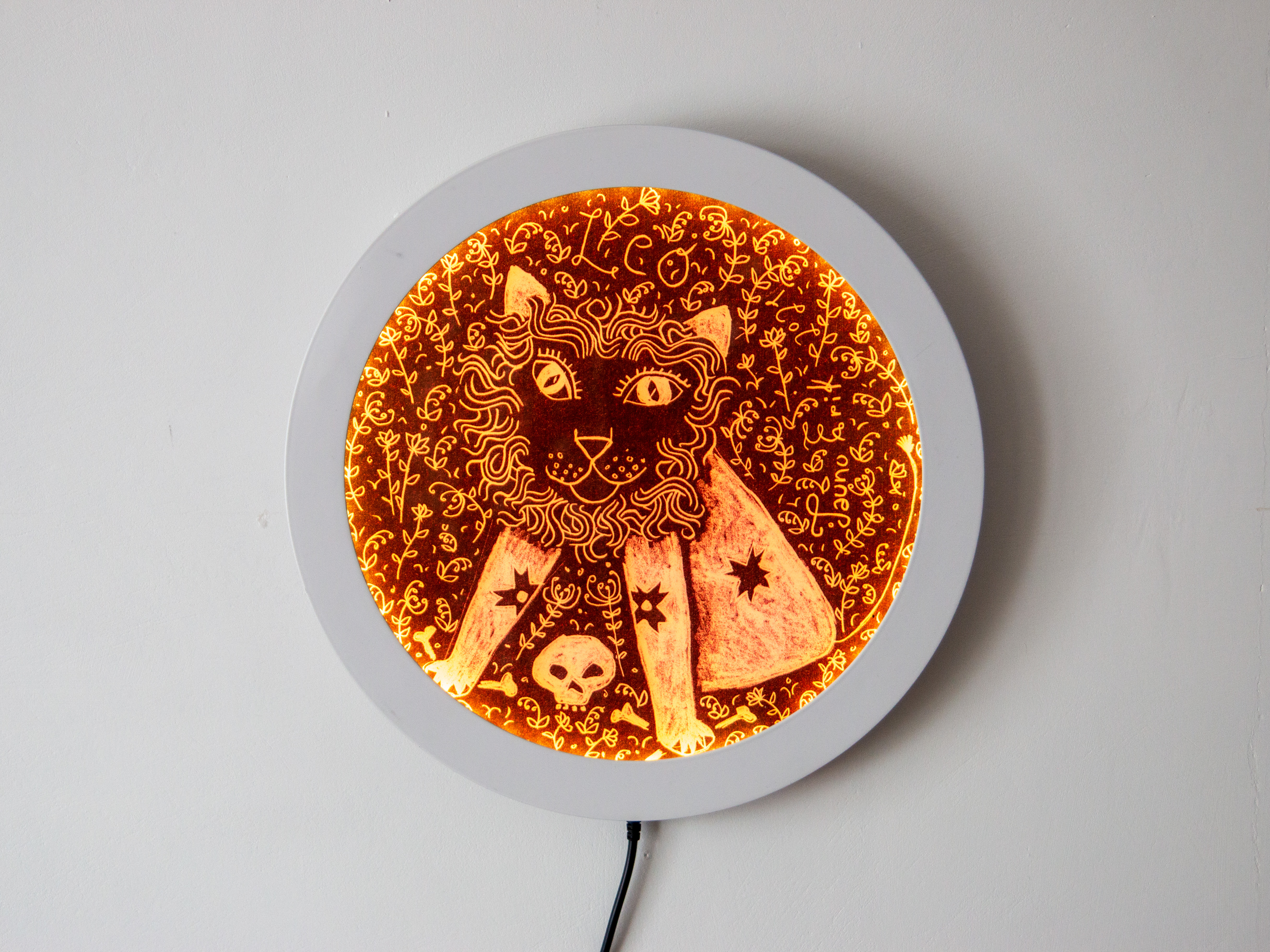
The radar sensor detects movements and the microcontroller (MCU) changes the RGB LEDs colours to react to human movement. And if the is no motion at certain time lights will turn off.
Three main components are:
/*
Lõvi lamp
Tauno Erik
18.02.2023
*/
#include <Arduino.h>
#include <Adafruit_NeoPixel.h>

const uint8_t RADAR_PIN = 4;
const uint8_t RGB_PIN = 3;
const uint8_t NUMPIXELS = 49;

uint8_t r = 0;
uint8_t g = 0;
uint8_t b = 0;

bool is_movement = false;
bool change_color = false;

uint32_t time_px_prev = 0;  // Millis
uint16_t px_interval = 50;  // Millis
const uint16_t OFF_TIME = 20000;
uint32_t no_movment_time = 0;

Adafruit_NeoPixel pixels(NUMPIXELS, RGB_PIN, NEO_GRB + NEO_KHZ800);

// Fill pixels pixels one after another with a color. pixels is NOT cleared
// first; anything there will be covered pixel by pixel. Pass in color
// (as a single 'packed' 32-bit value, which you can get by calling
// pixels.Color(red, green, blue) as shown in the loop() function above),
// and a delay time (in milliseconds) between pixels.
void colorWipe(uint32_t color, int wait) {
  for(int i=0; i<pixels.numPixels(); i++) { // For each pixel in pixels...
    pixels.setPixelColor(i, color);         //  Set pixel's color (in RAM)
    pixels.show();                          //  Update pixels to match
    delay(wait);                           //  Pause for a moment
  }
}


// Rainbow cycle along whole pixels. Pass delay time (in ms) between frames.
void rainbow(int wait) {
  // Hue of first pixel runs 5 complete loops through the color wheel.
  // Color wheel has a range of 65536 but it's OK if we roll over, so
  // just count from 0 to 5*65536. Adding 256 to firstPixelHue each time
  // means we'll make 5*65536/256 = 1280 passes through this loop:
  for(long firstPixelHue = 0; firstPixelHue < 5*65536; firstPixelHue += 256) {
    // pixels.rainbow() can take a single argument (first pixel hue) or
    // optionally a few extras: number of rainbow repetitions (default 1),
    // saturation and value (brightness) (both 0-255, similar to the
    // ColorHSV() function, default 255), and a true/false flag for whether
    // to apply gamma correction to provide 'truer' colors (default true).
    pixels.rainbow(firstPixelHue);
    // Above line is equivalent to:
    // pixels.rainbow(firstPixelHue, 1, 255, 255, true);
    pixels.show(); // Update pixels with new contents
    delay(wait);  // Pause for a moment
  }
}


void setup() {
  pinMode(RADAR_PIN, INPUT);

  pixels.begin();
  pixels.show();            // Turn OFF all pixels ASAP
  pixels.setBrightness(50); // Set BRIGHTNESS to about 1/5 (max = 255)

  randomSeed(analogRead(0));
  rainbow(3);
  colorWipe(pixels.Color(0, 0, 0), 0);
}

void loop() {
  uint32_t time_now = millis();

  is_movement = digitalRead(RADAR_PIN);

  if (is_movement) {
    change_color = true;
    no_movment_time = time_now;
  } else {
    change_color = false;
  }

   // All LEDs off
  if (time_now - no_movment_time >= OFF_TIME) {
    colorWipe(pixels.Color(0, 0, 0), 0);
  }

  // Colour change routine
  if (time_now - time_px_prev >= px_interval) {
    time_px_prev = time_now;

    if (change_color) {
      r = random(0, 255);
      g = random(0, 255);
      b = random(0, 255);
      colorWipe(pixels.Color(r, g, b), 50); // Blue
      change_color = false;
    }
  }


}
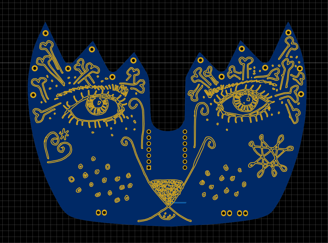
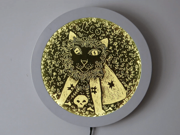
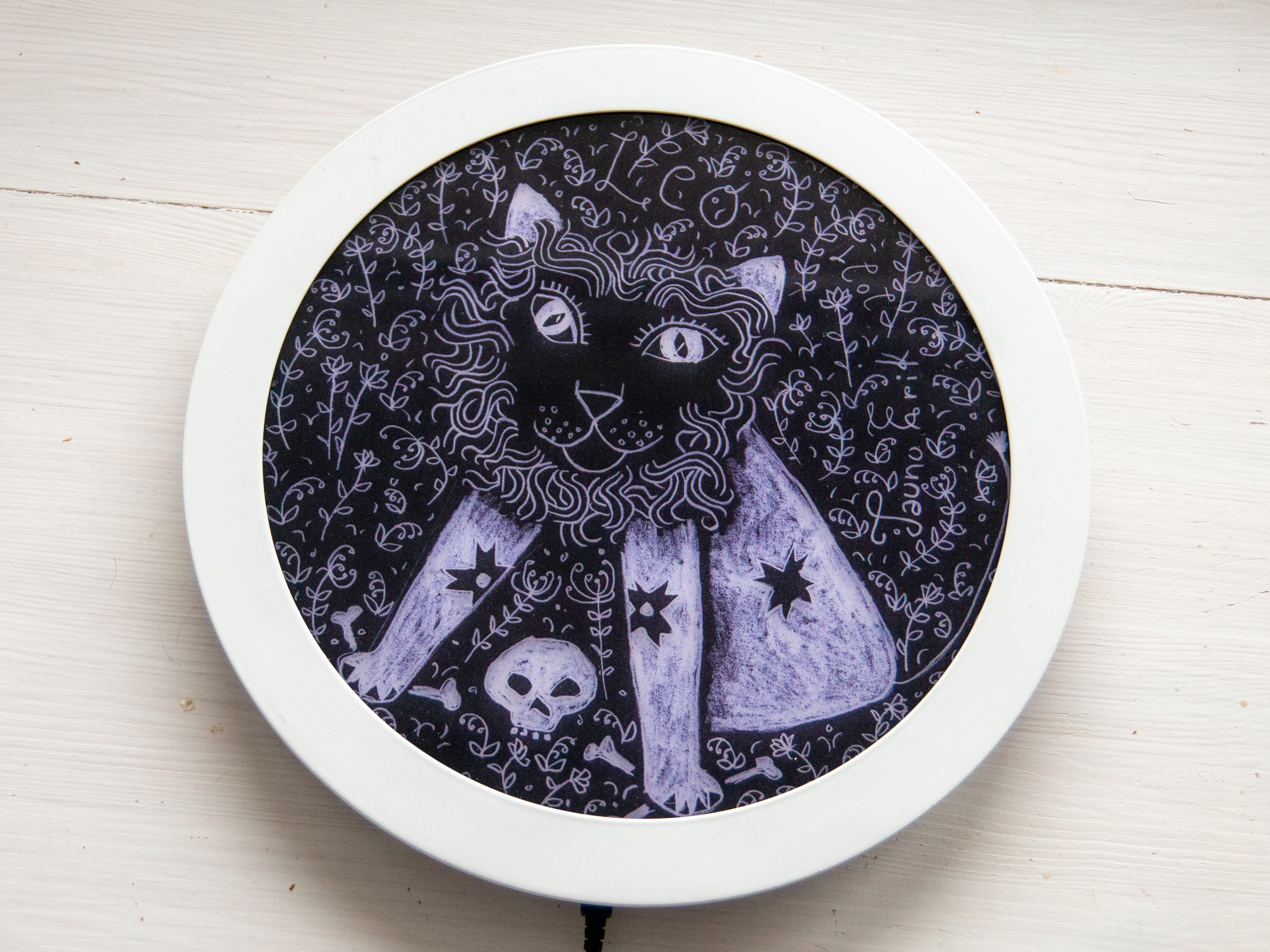
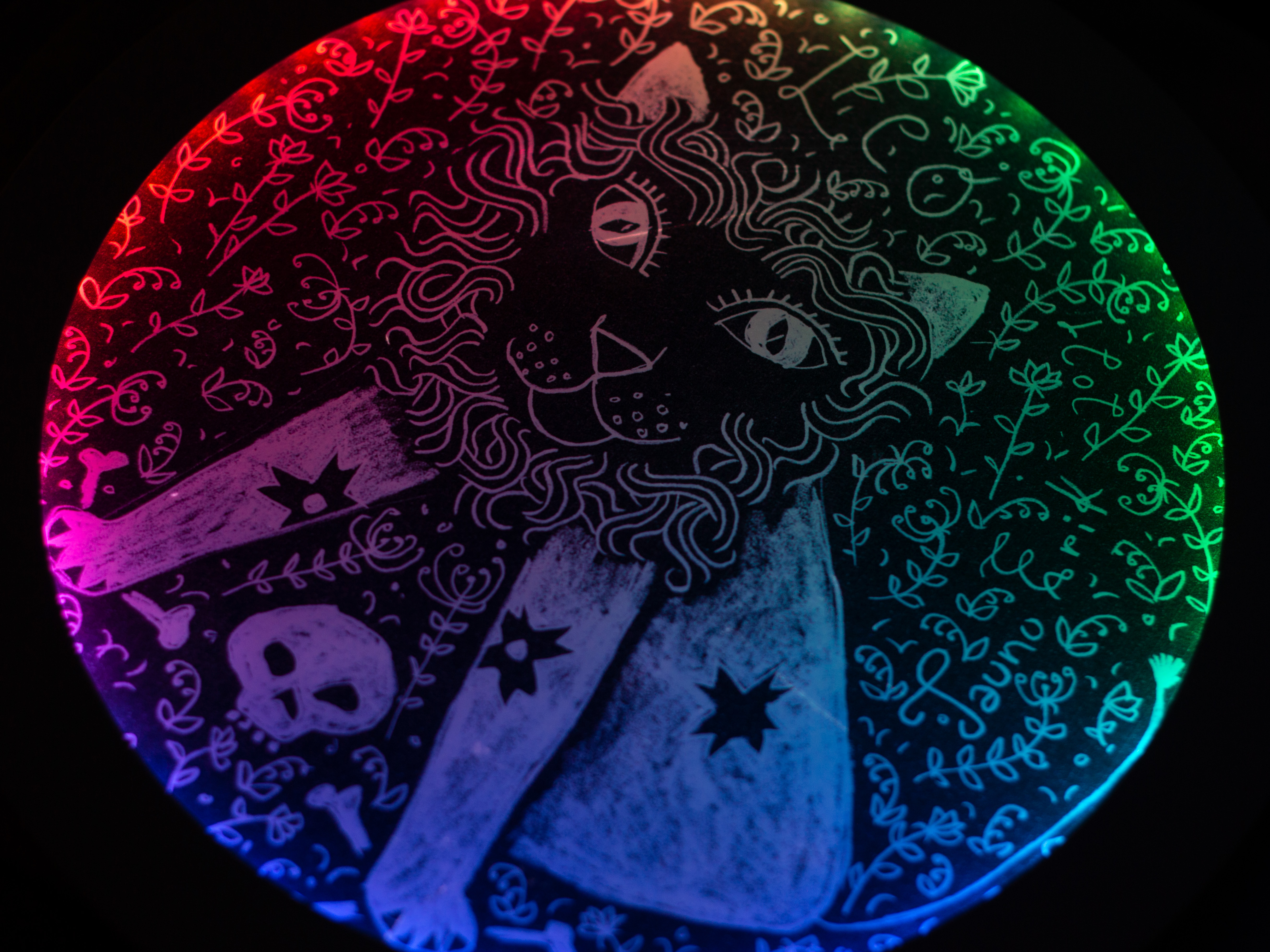
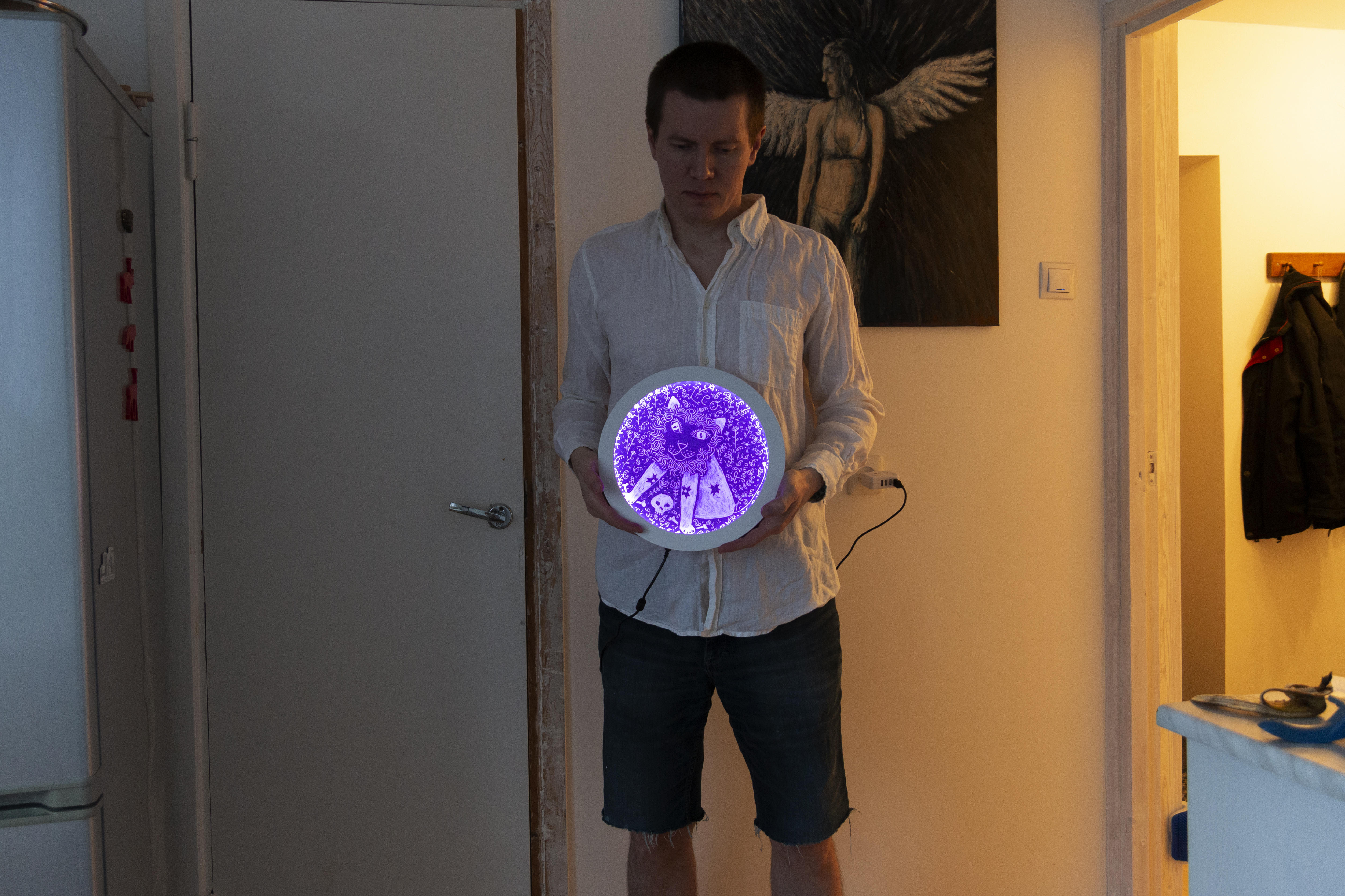
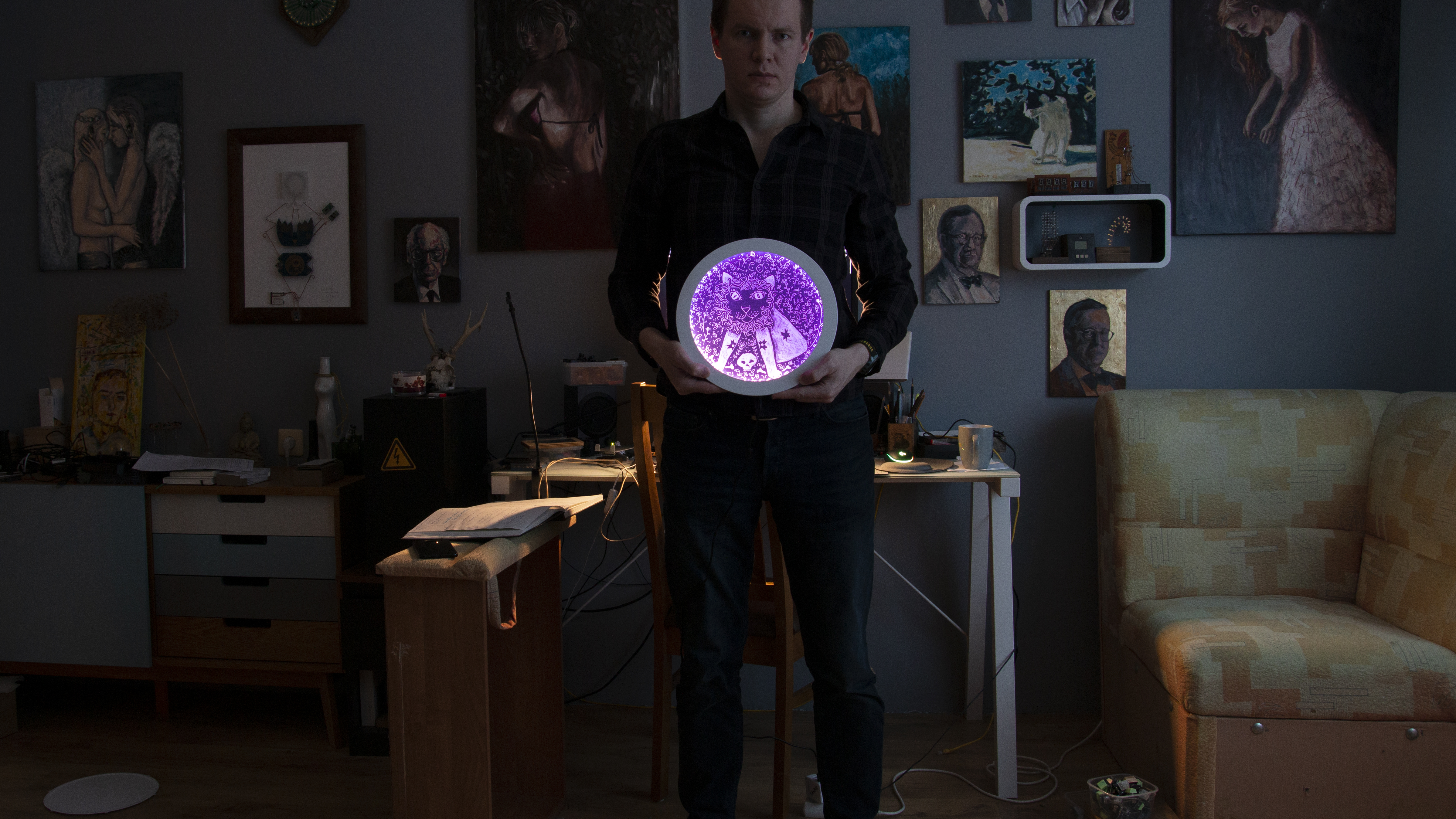
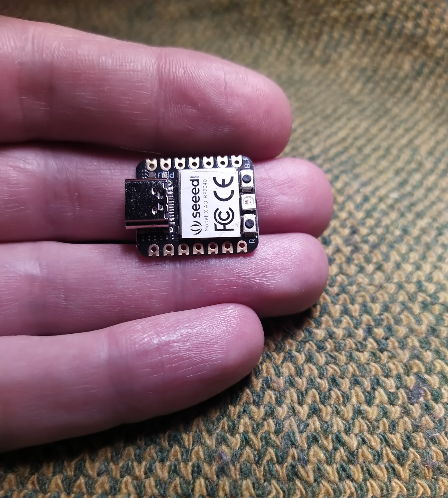
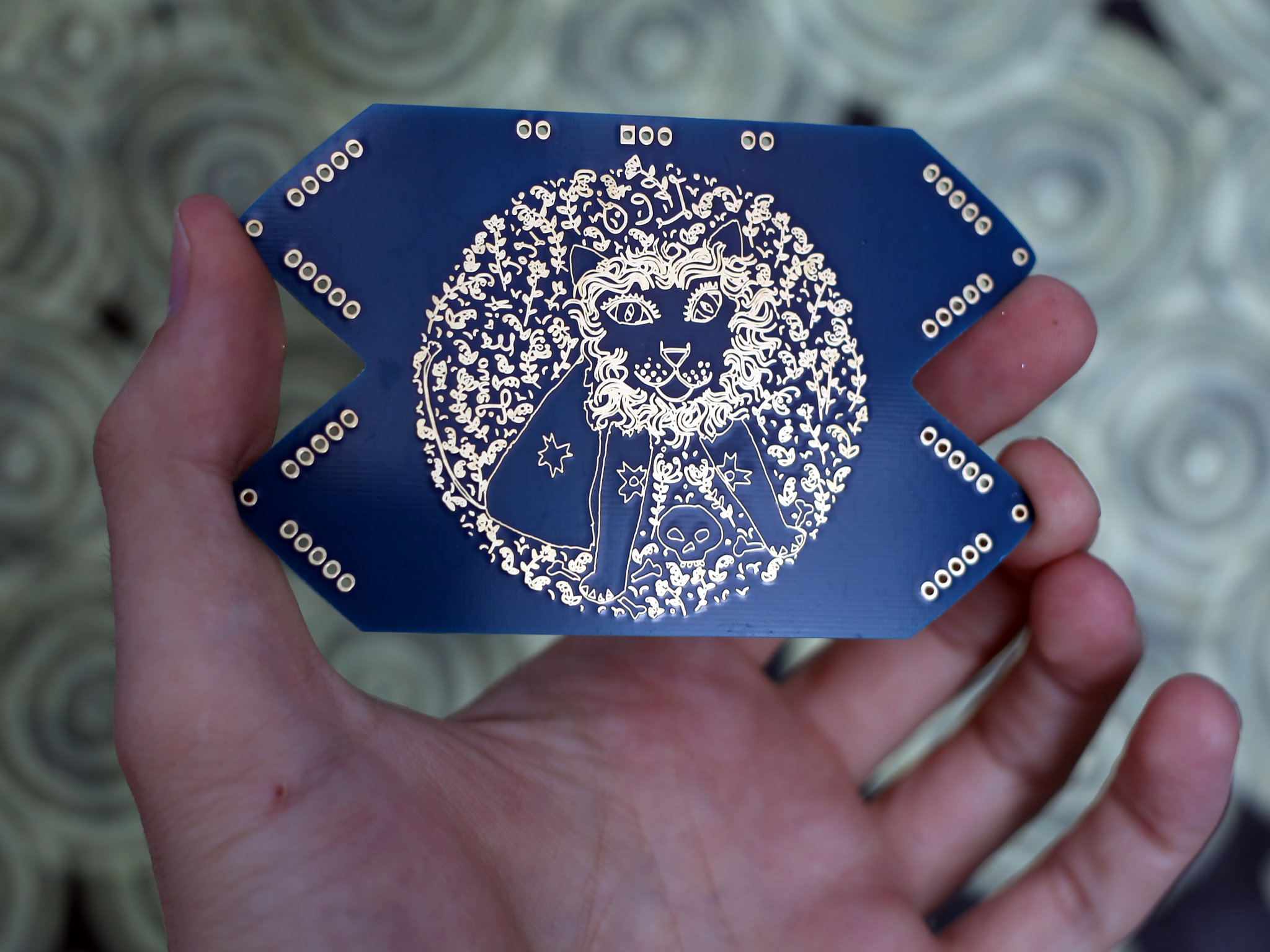
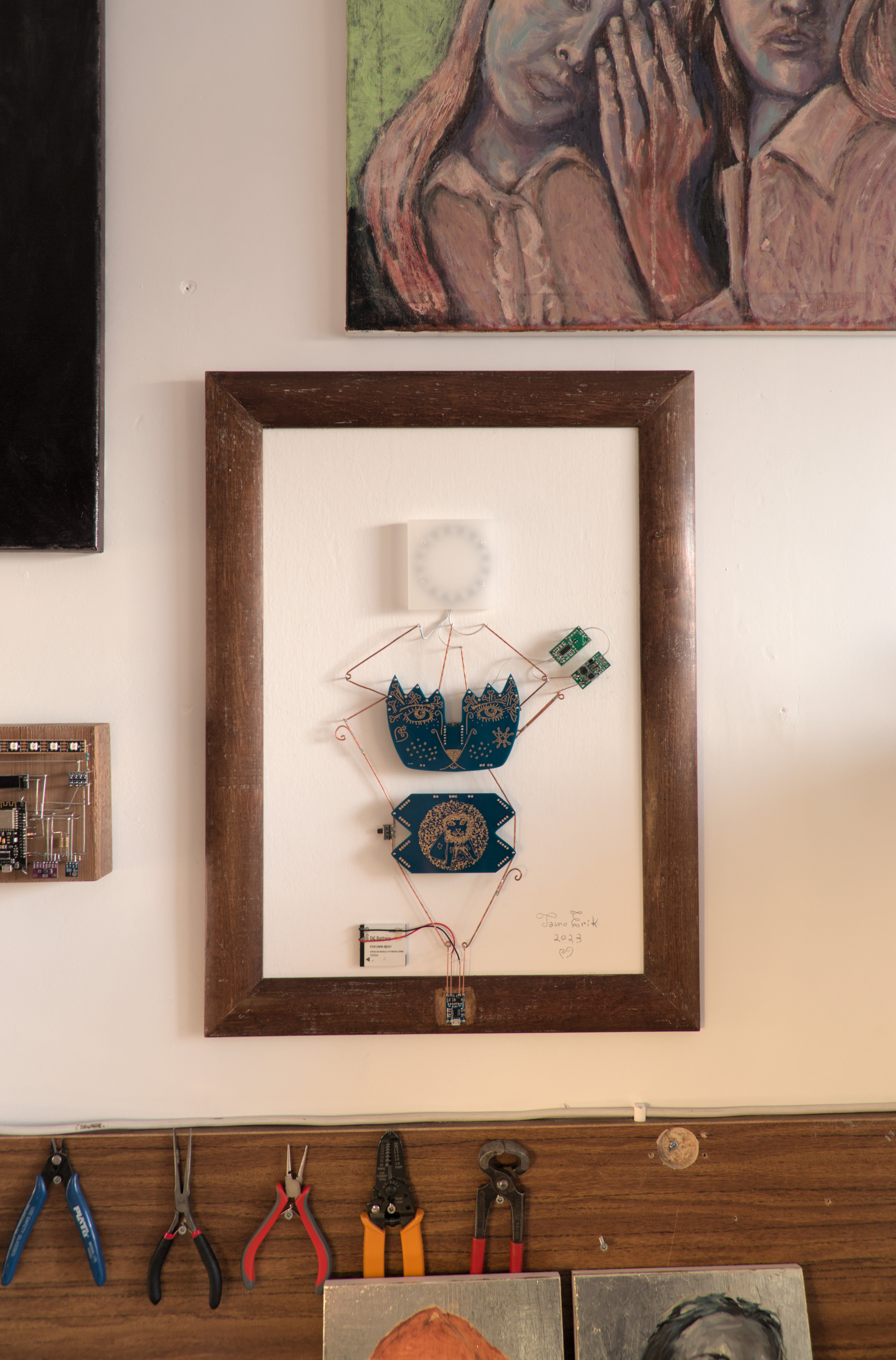
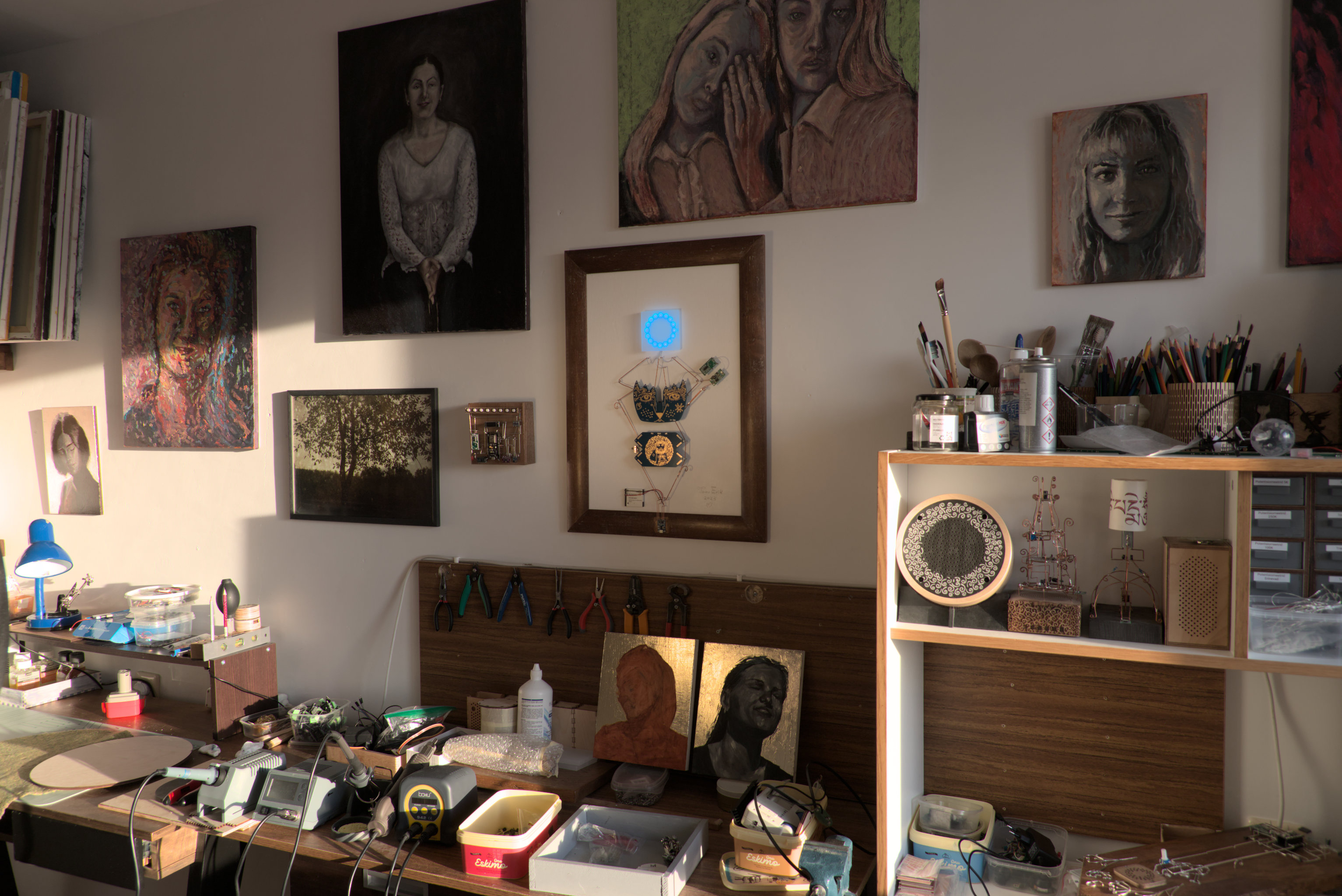
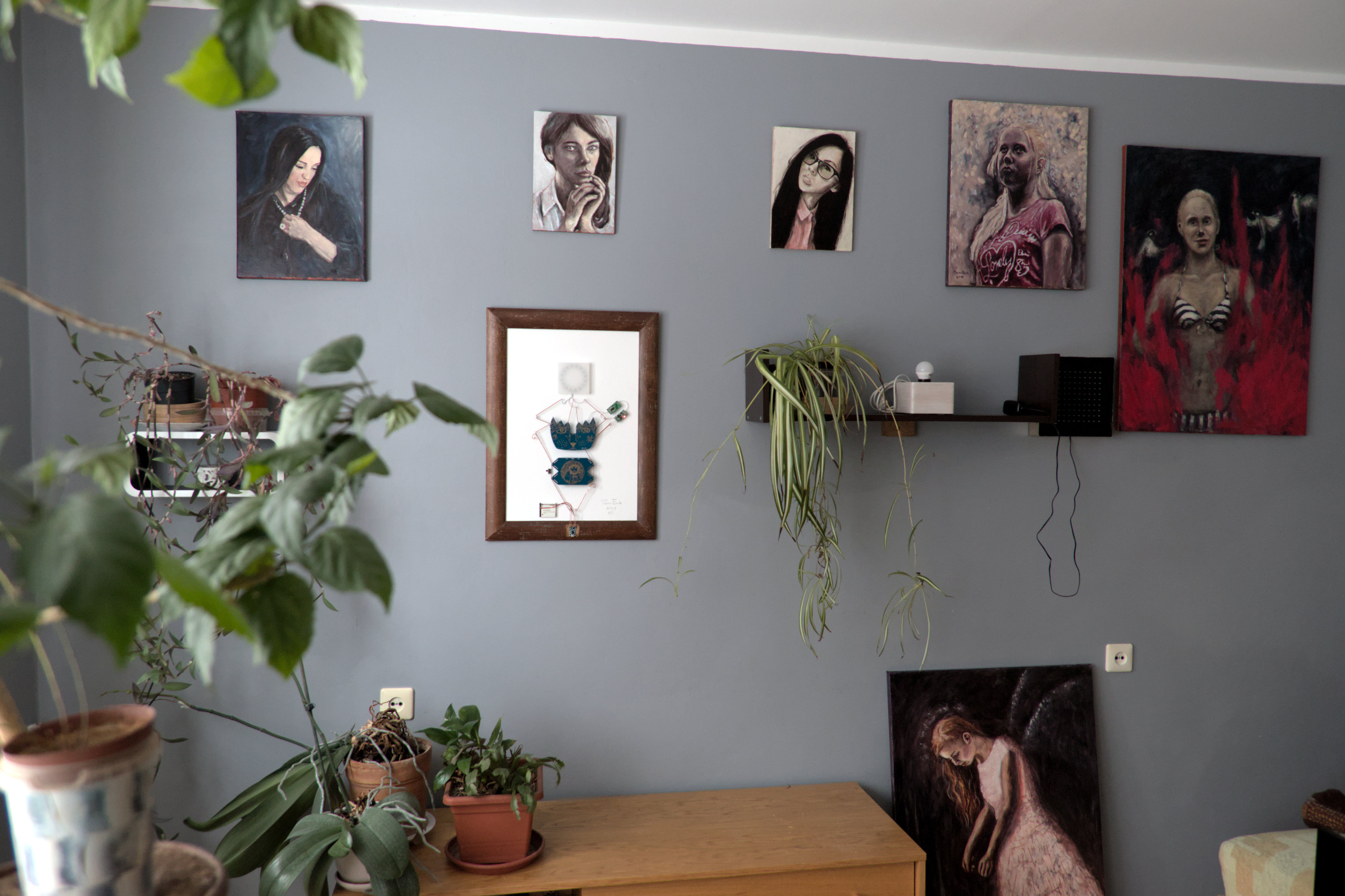
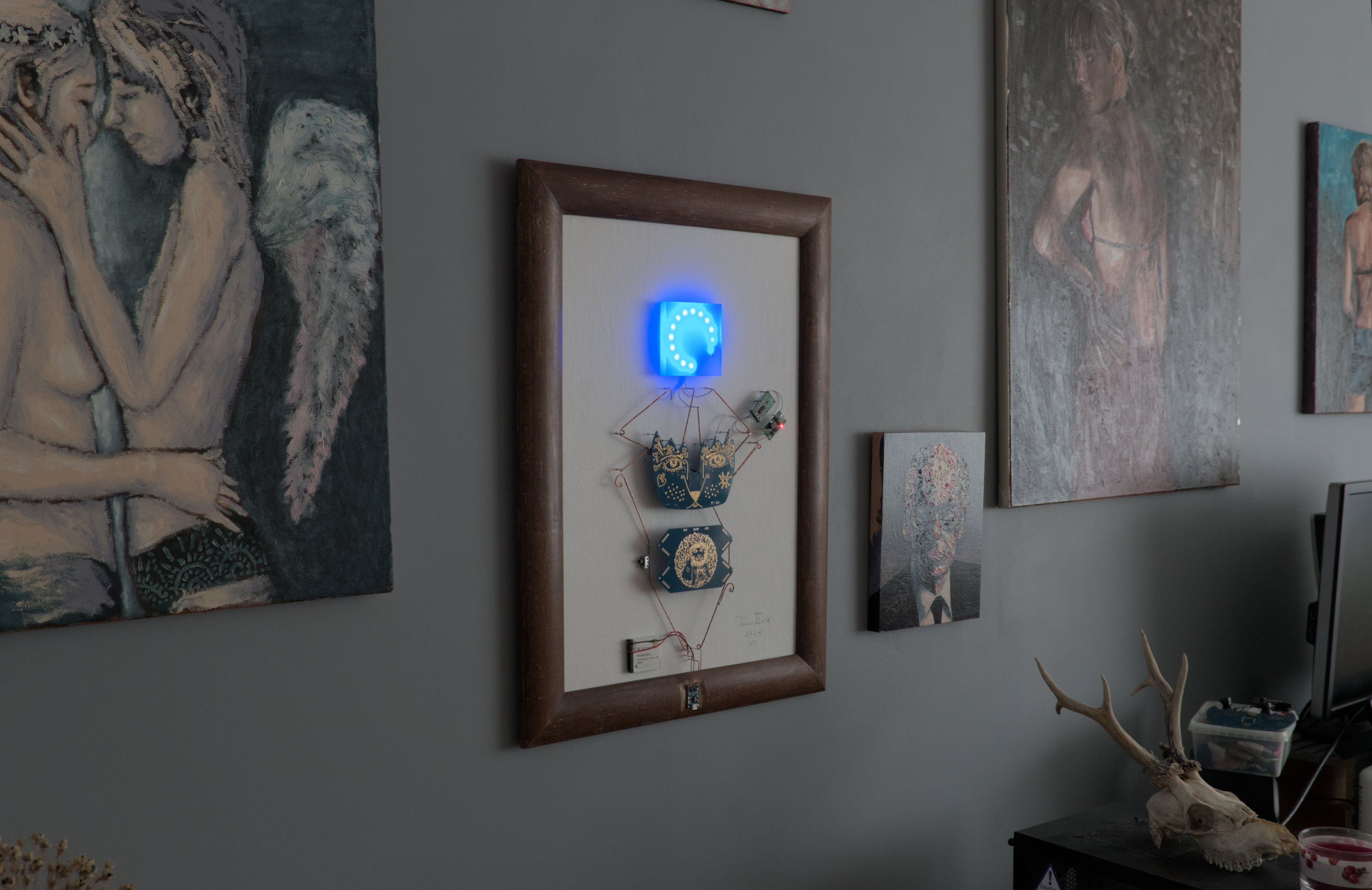
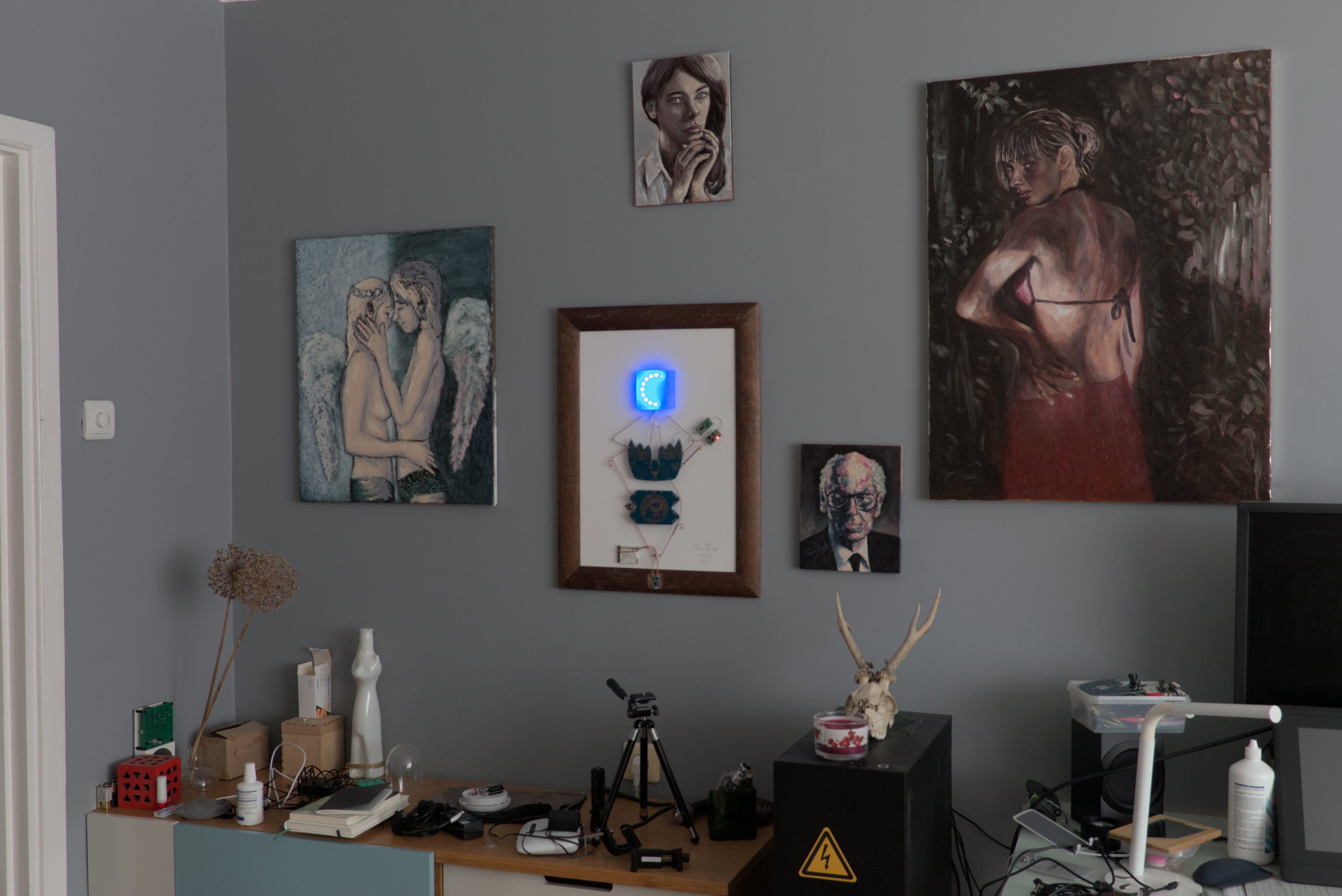
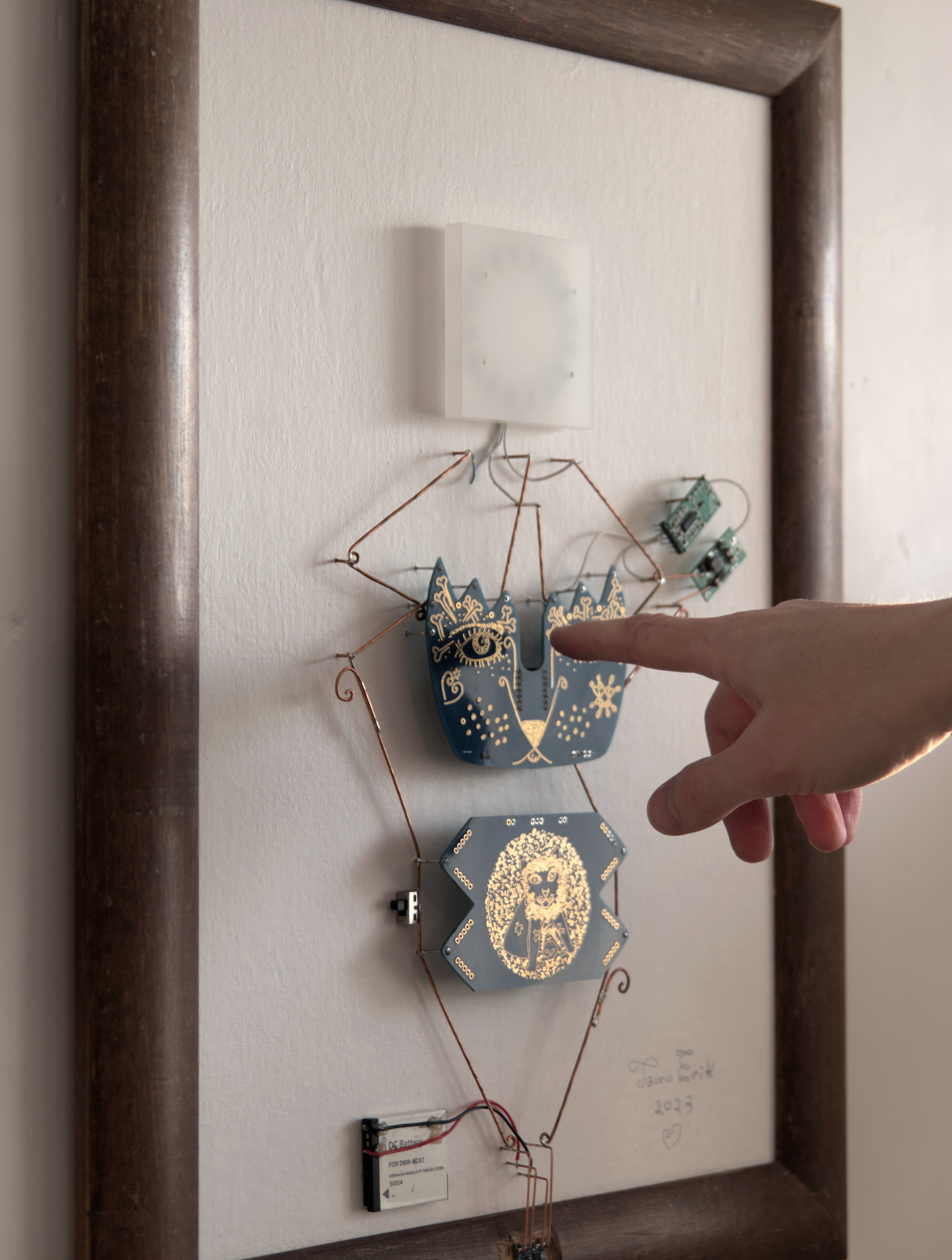
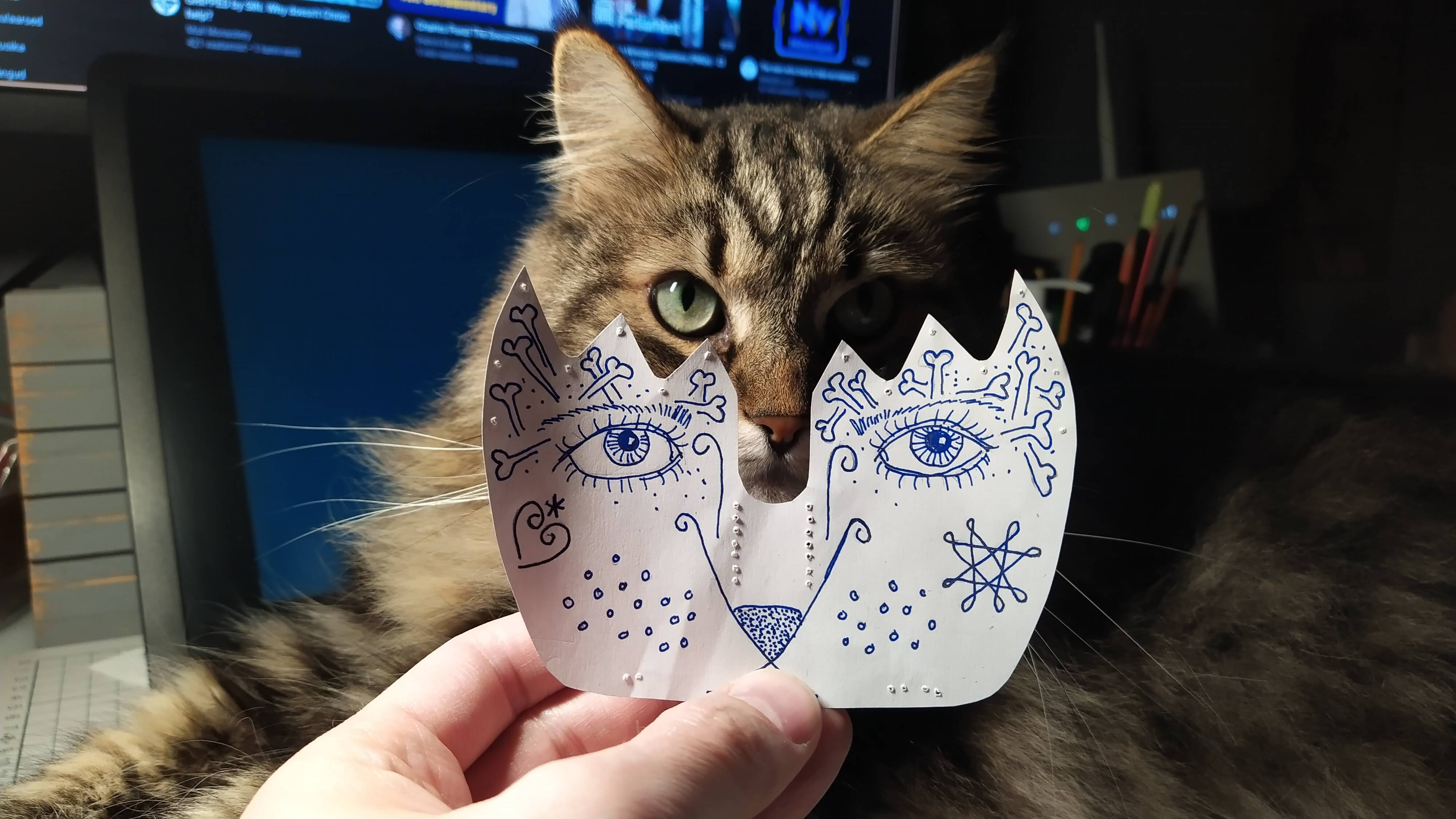
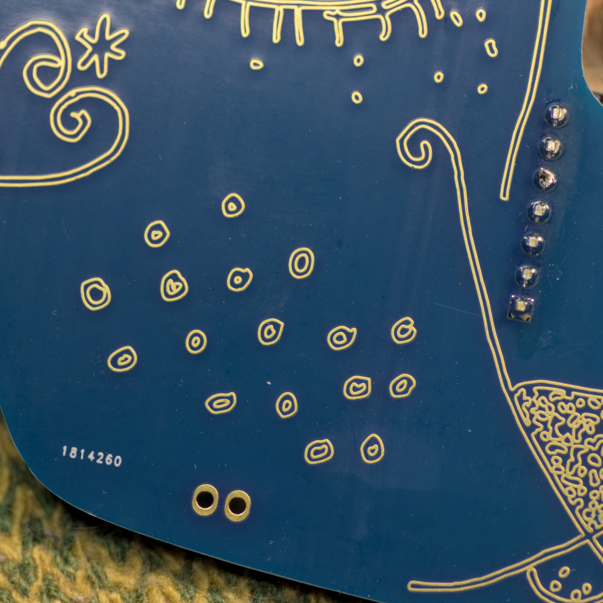
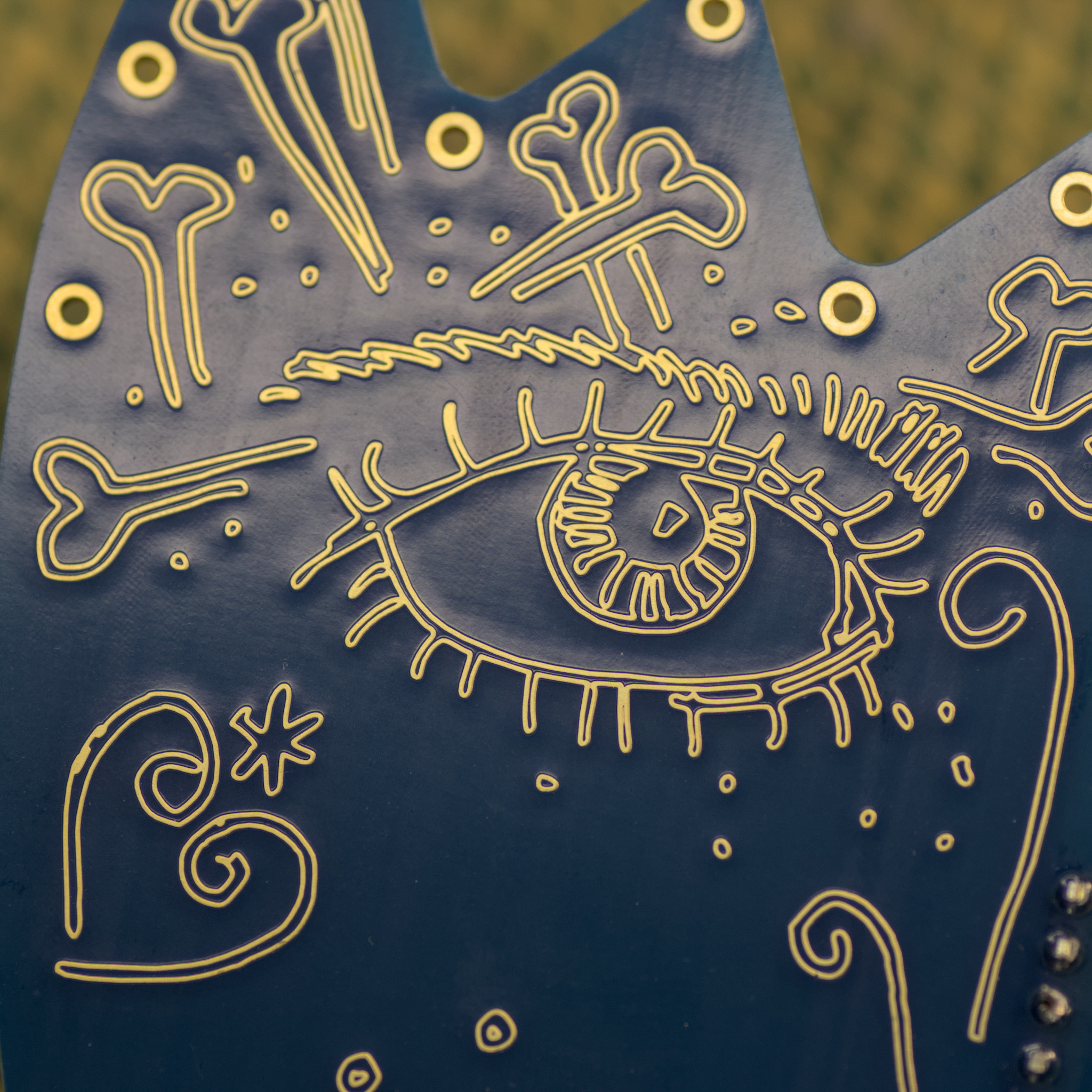
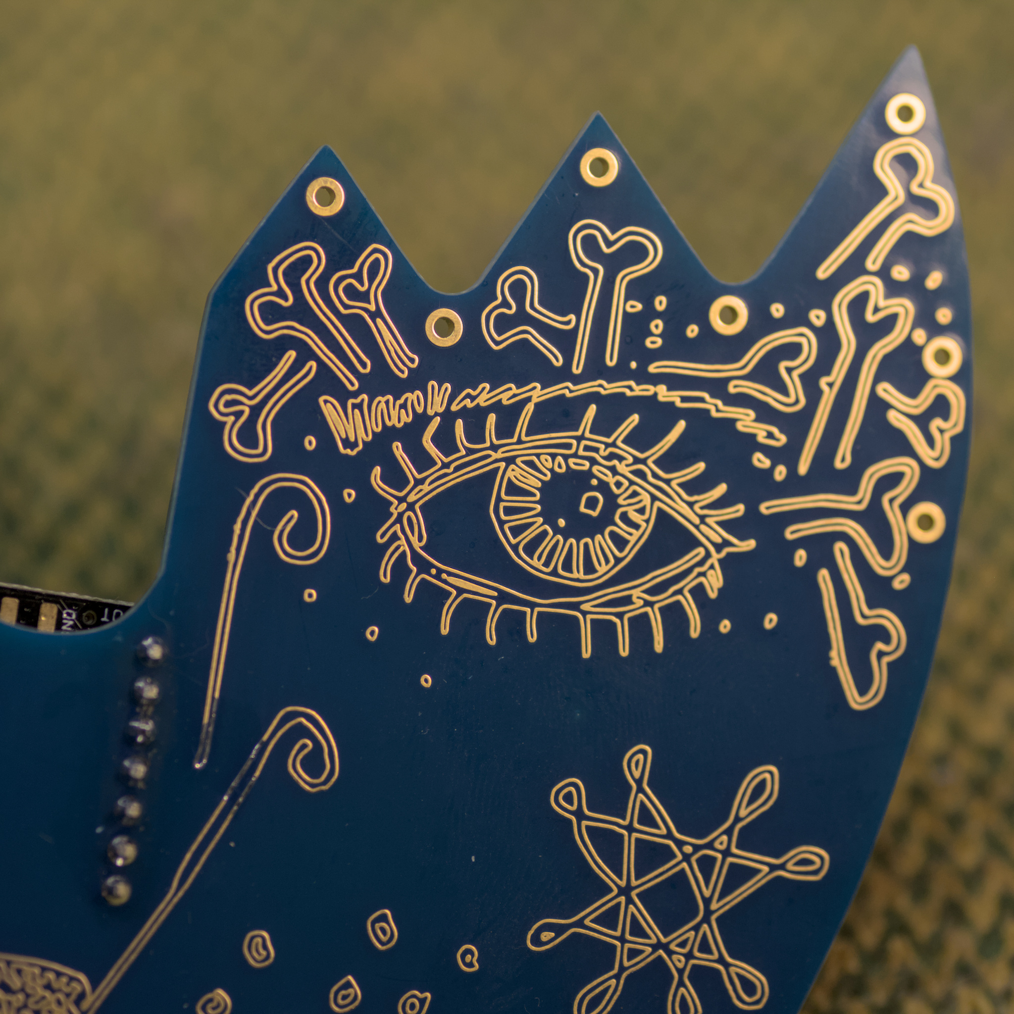
The Watchman is an Electronic Sculpture.
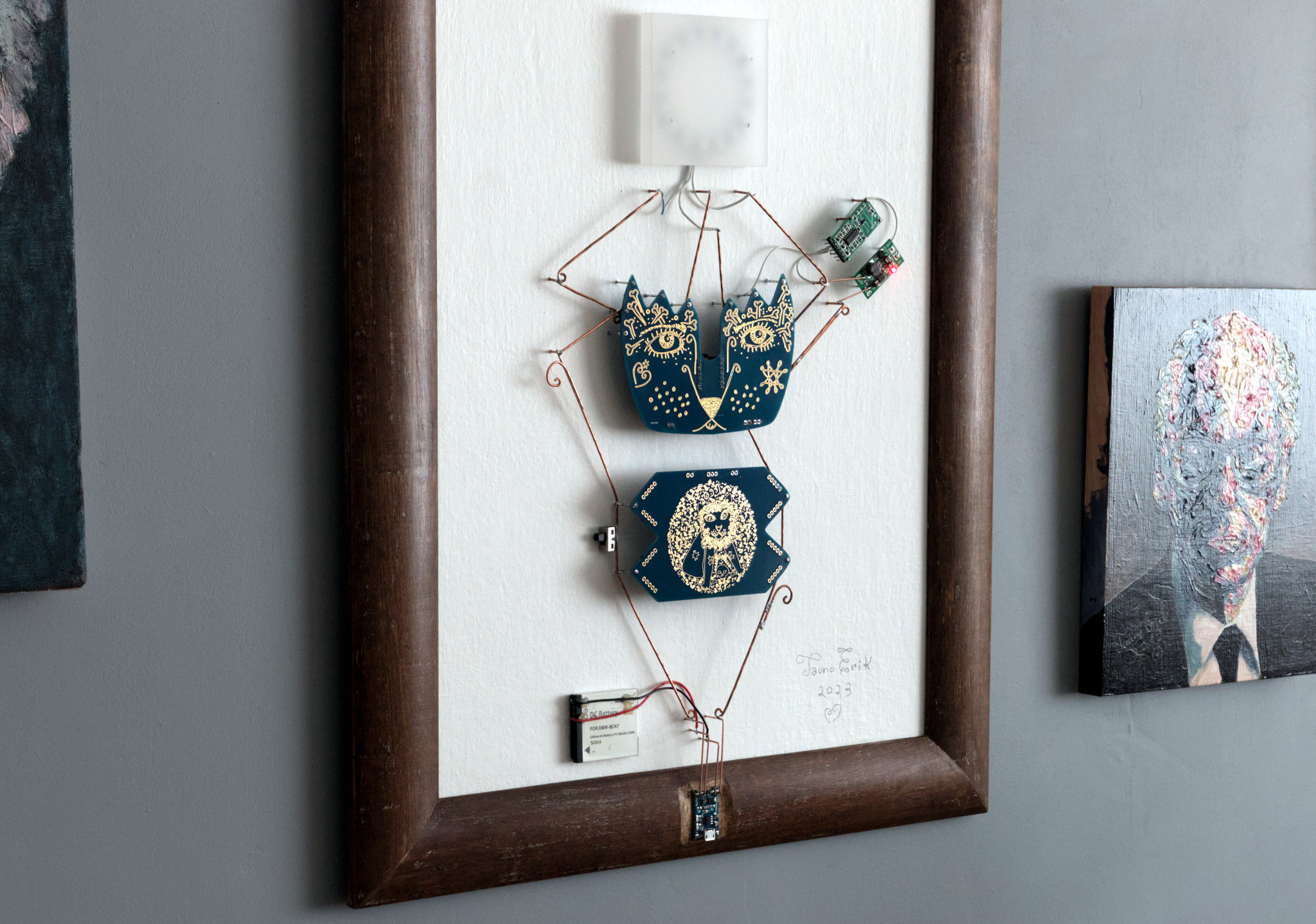
The Watchman is an electronic wall sculpture that combines art, night lighting and security. The working principle is very simple. It all is built around of Seeed Xiao RP2040 microcontroller board. Powered by a 3.7v Lithium-ion battery. RCWL-0516 doppler radar sensor detects the motion and sends the signal to MCU. Because the sensor’s working voltage is above 4 voltage, I added a voltage booster. When the MCU gets a signal, its lights up the circular RGB LEDs.

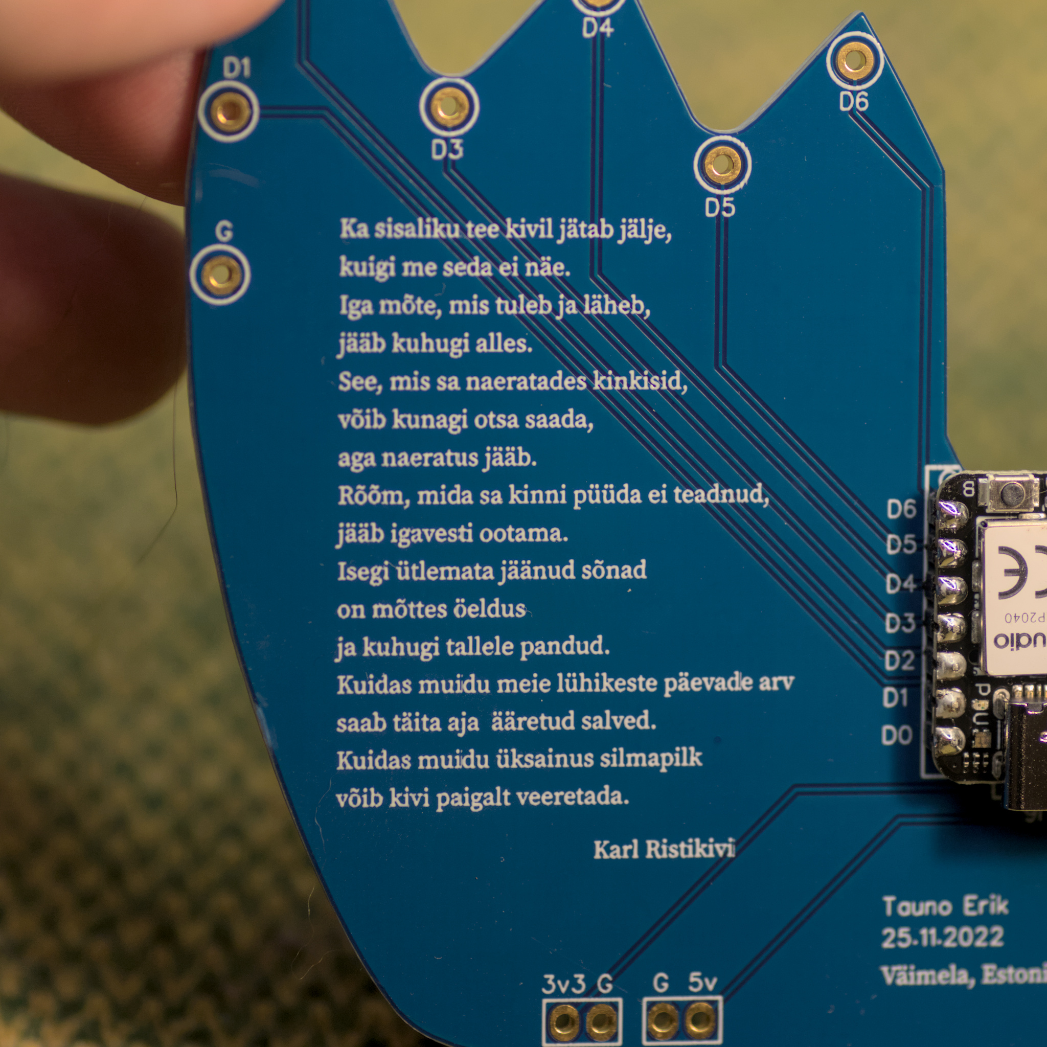
The outer dimensions are 440 x 590 mm.
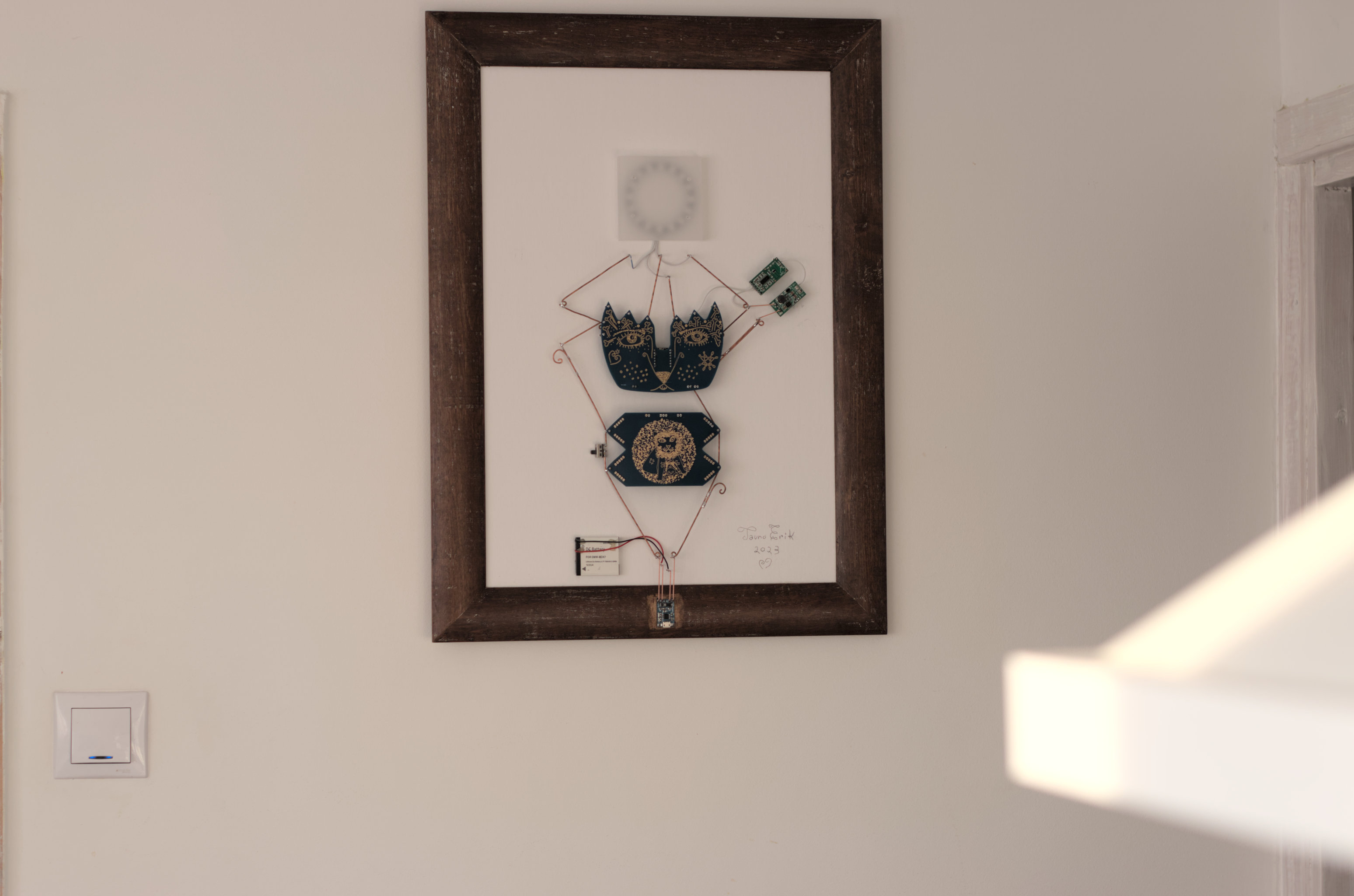
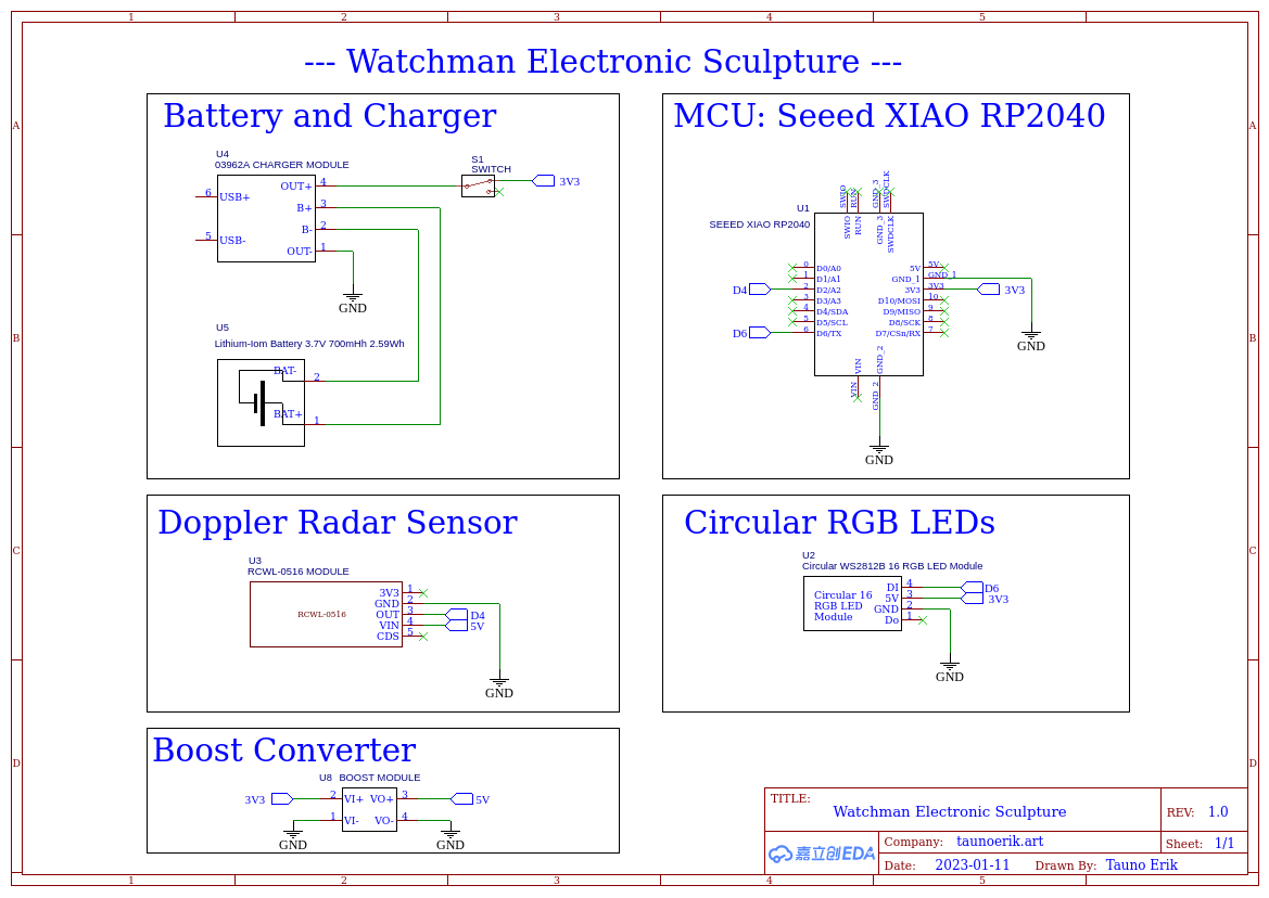
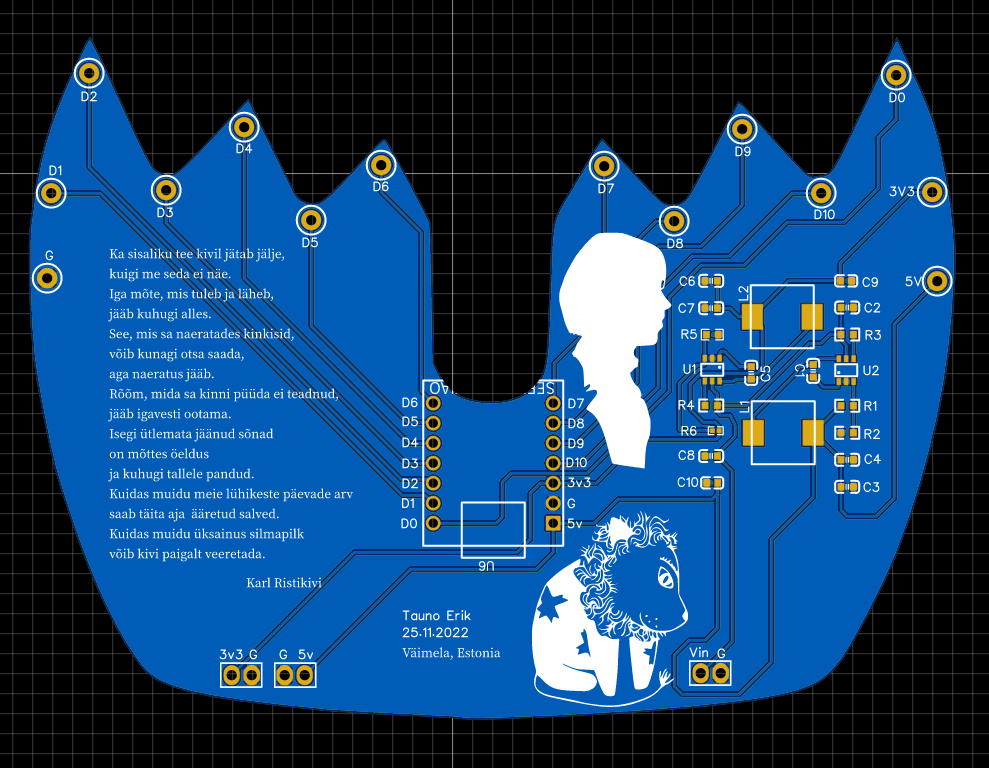
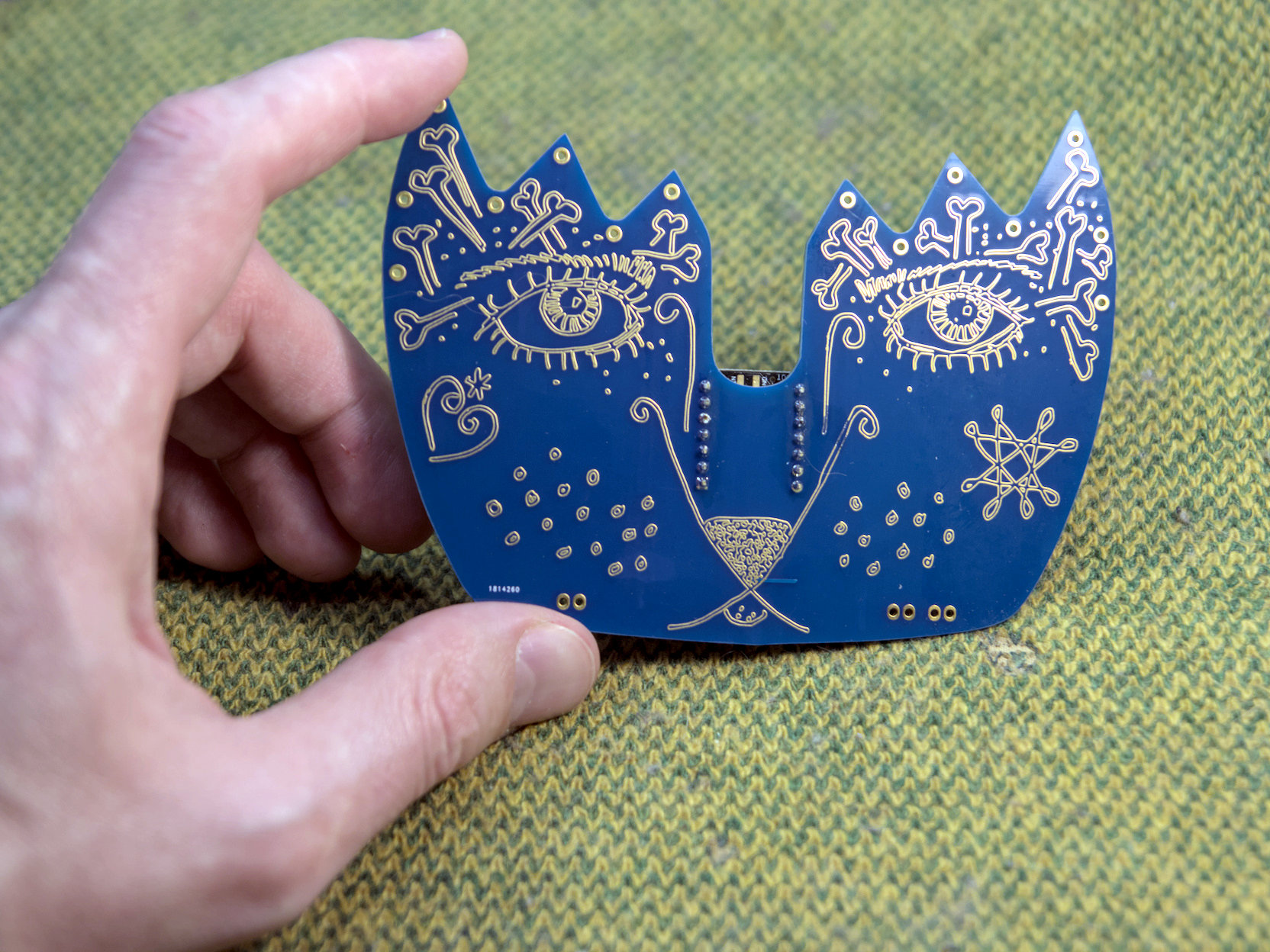
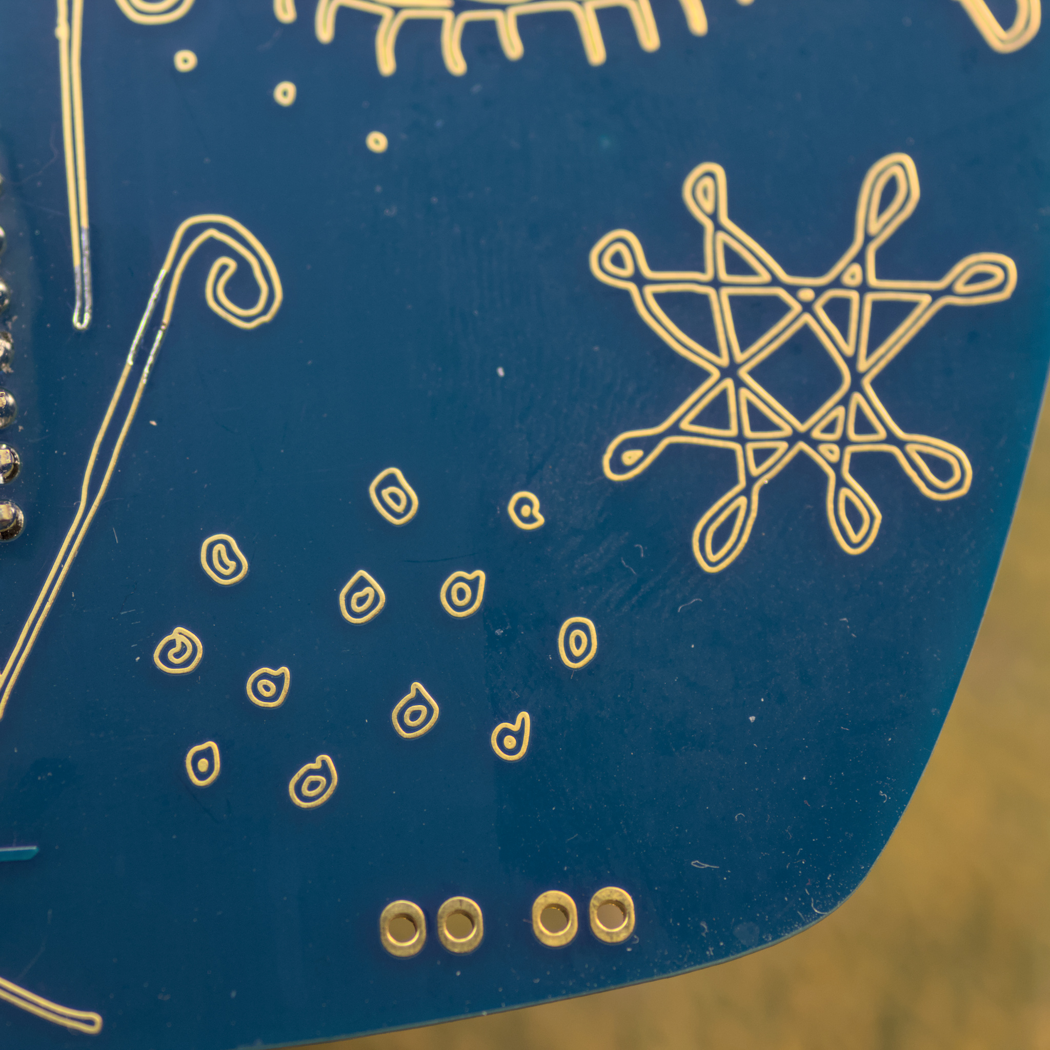
It has two custom-made PCBs. Both have my drawings on them. The face-shape one is kindly made by Seeed Studio Fusion service. It holds the MCU board and has all the input/output pins.
I have defined some colours for RGB LEDs:
#define AMBER    255, 100, 0
#define AQUA     50, 255, 255
#define BLUE     0, 0, 255
#define CYAN     0, 255, 255
#define GOLD     255, 222, 30
#define GREEN    0, 255, 0
#define JADE     0, 255, 40
#define MAGENTA  255, 0, 20
#define OLD_LACE 253, 245, 230
#define ORANGE   255, 40, 0
#define PINK     242, 90, 255
#define PURPLE   180, 0, 255
#define RED      255, 0, 0
#define TEAL     0, 255, 120
#define WHITE    255, 255, 255
#define YELLOW   255, 150, 0
The rest of the code is on the GitHub repository.
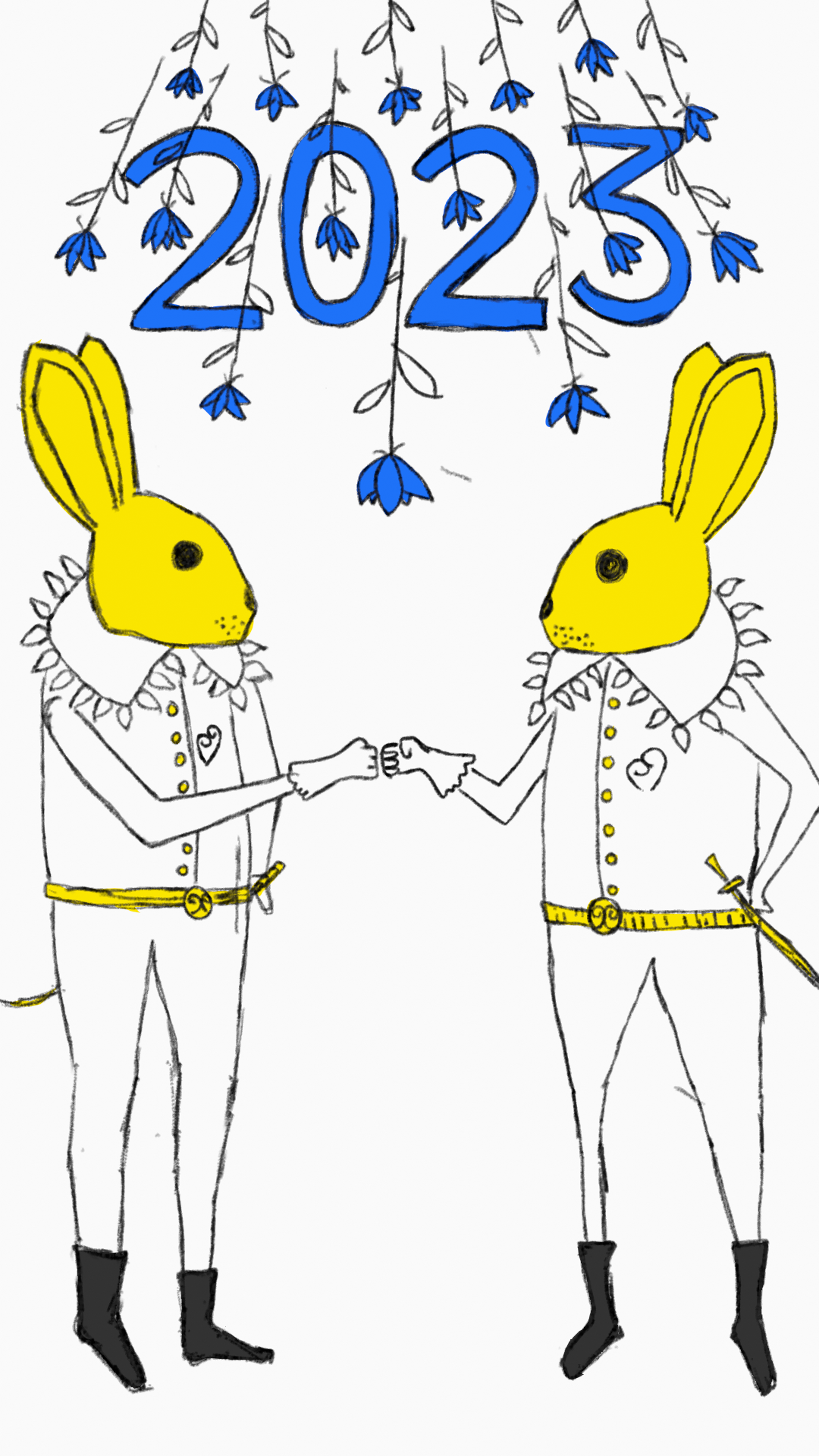
This animation is inspired by the Chinese new year. Made with Blender grease pencil.


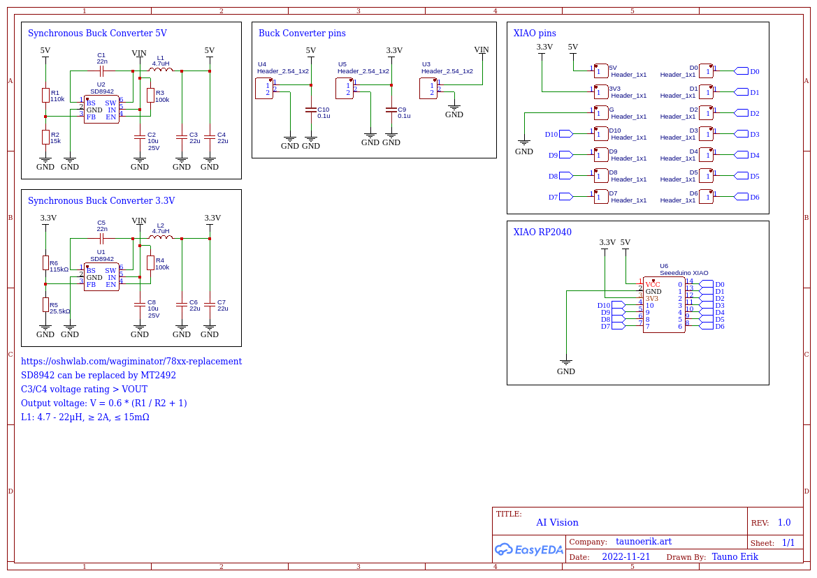
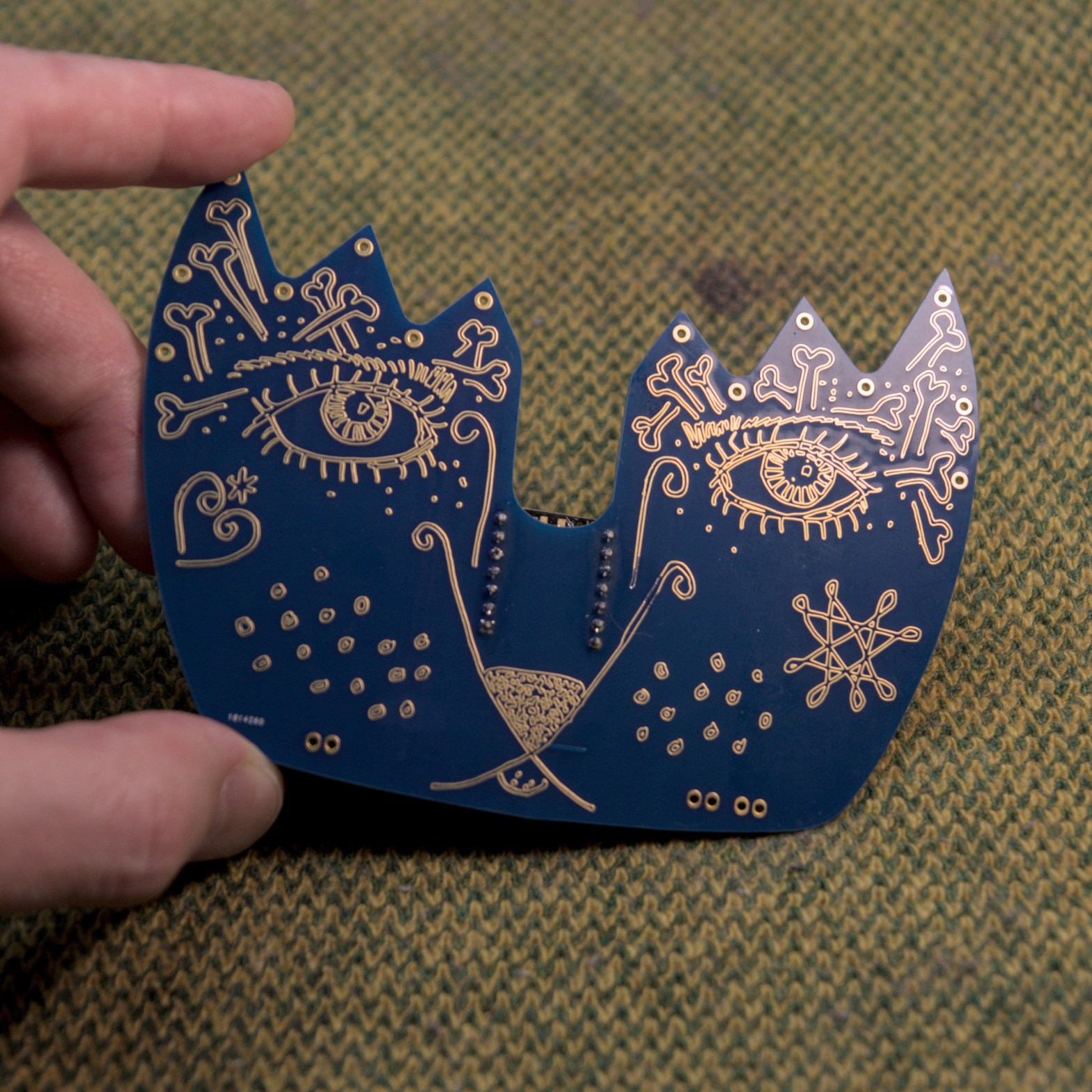
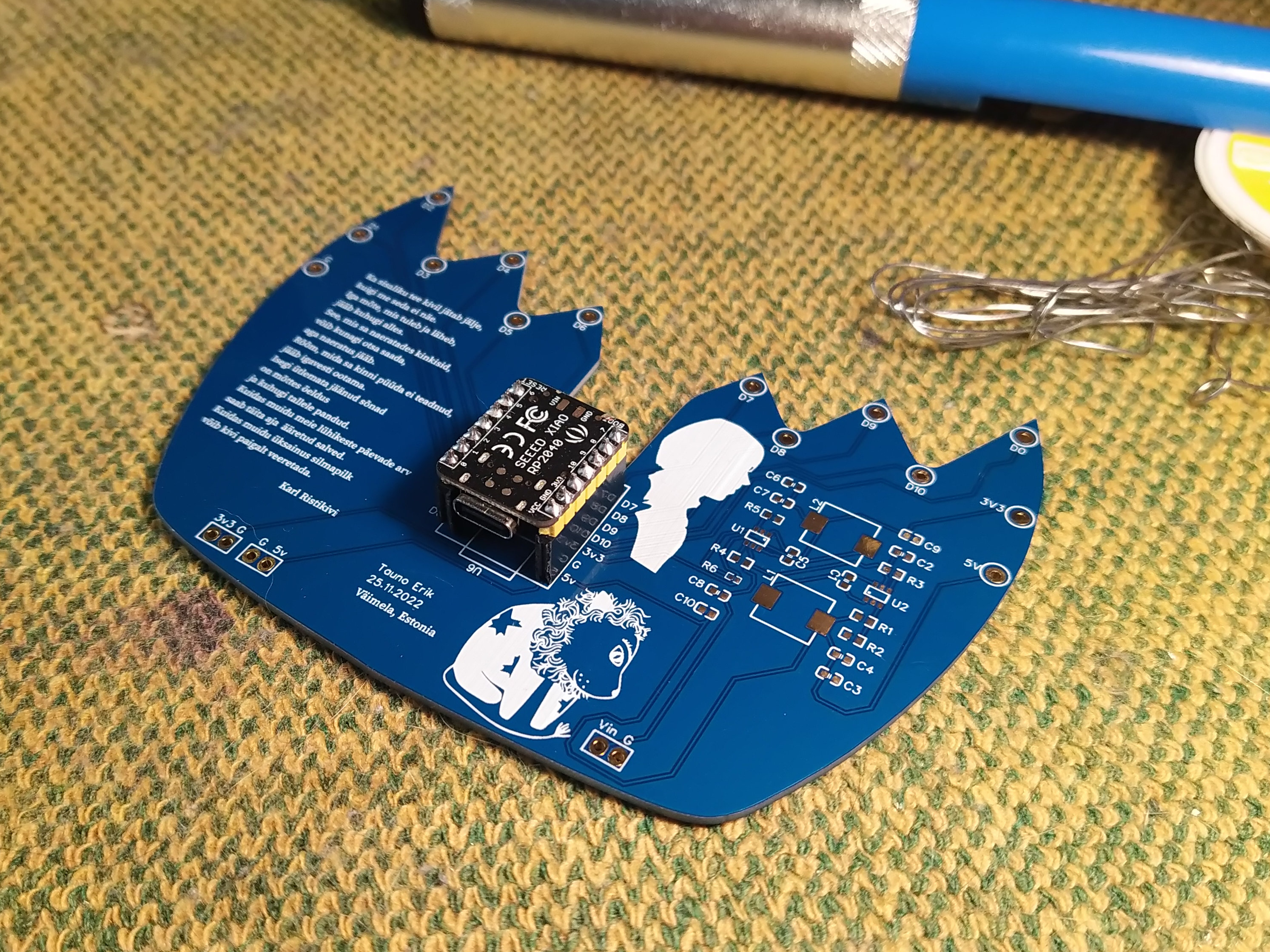
My face-shape PCBs have arrived – kindly made by Seeed Studio Fusion service. On the backside, there are one XIAO RP2040 microcontroller and two synchronous buck converters to make 5 and 3.3 voltages.

I found these Synchronous Buck Converter schematics, made by @wagiminator I incorporated them into my board design and it works pretty well. Input voltage 4.5V – 16V. The output voltage depends on resistors. And I didn’t have the right size SMD inductors so I used through-hole ones.
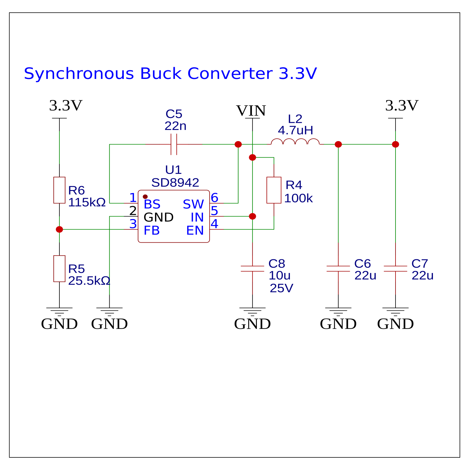
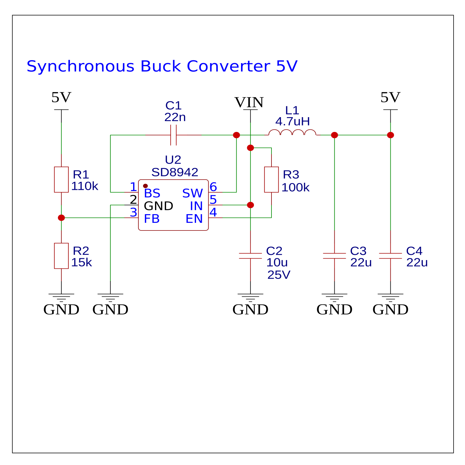
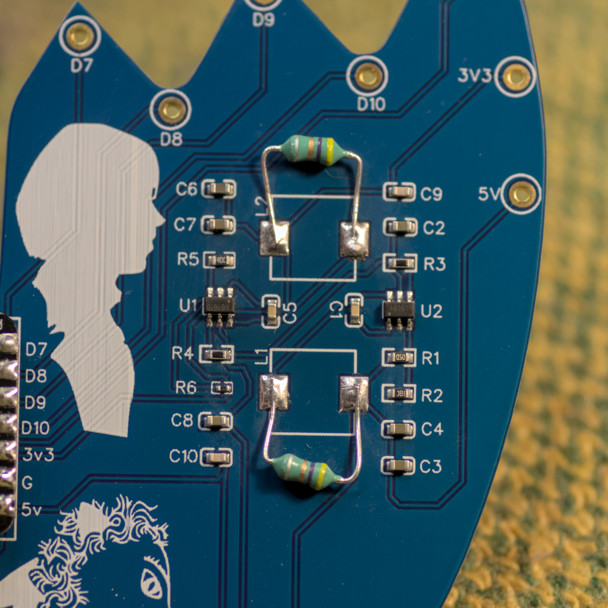
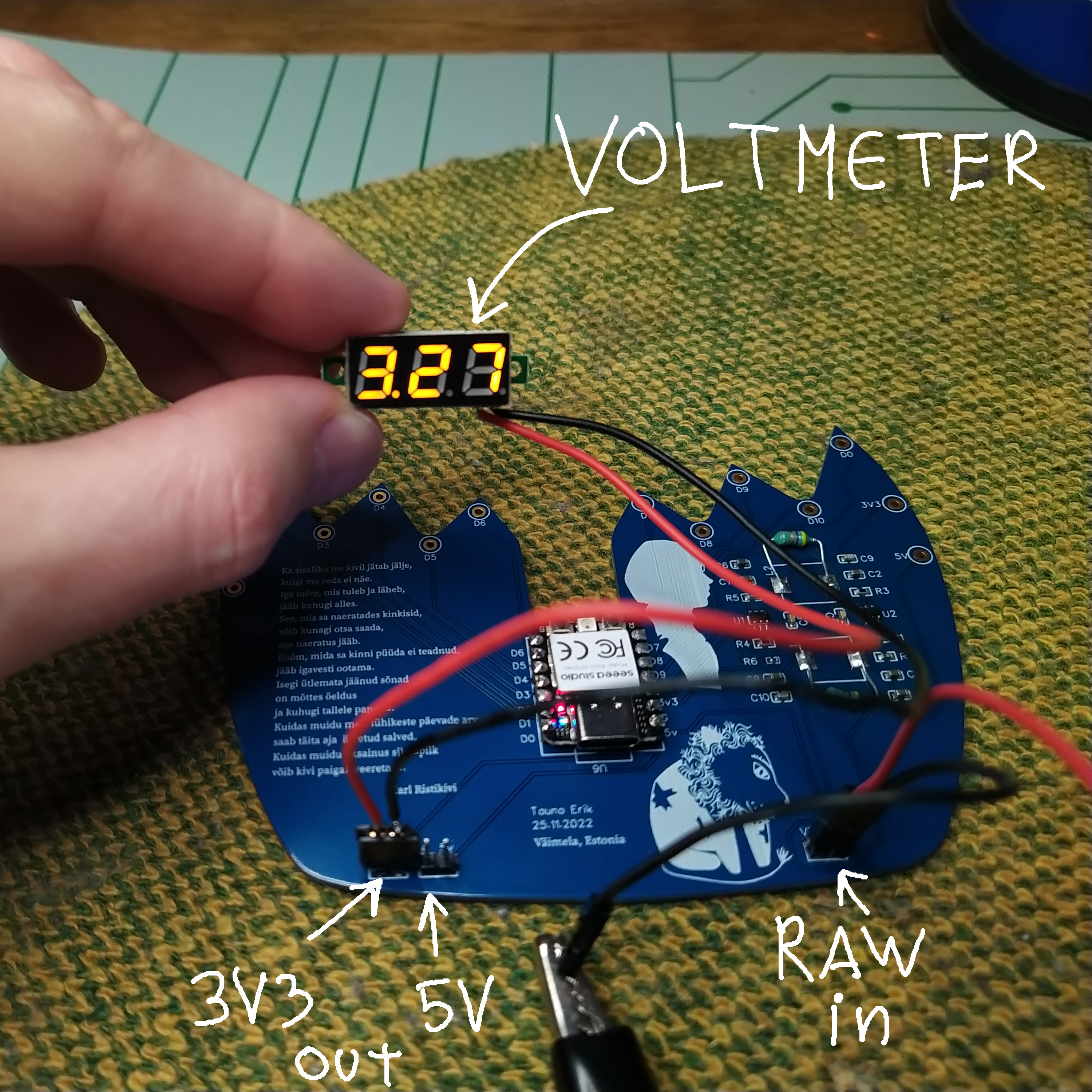
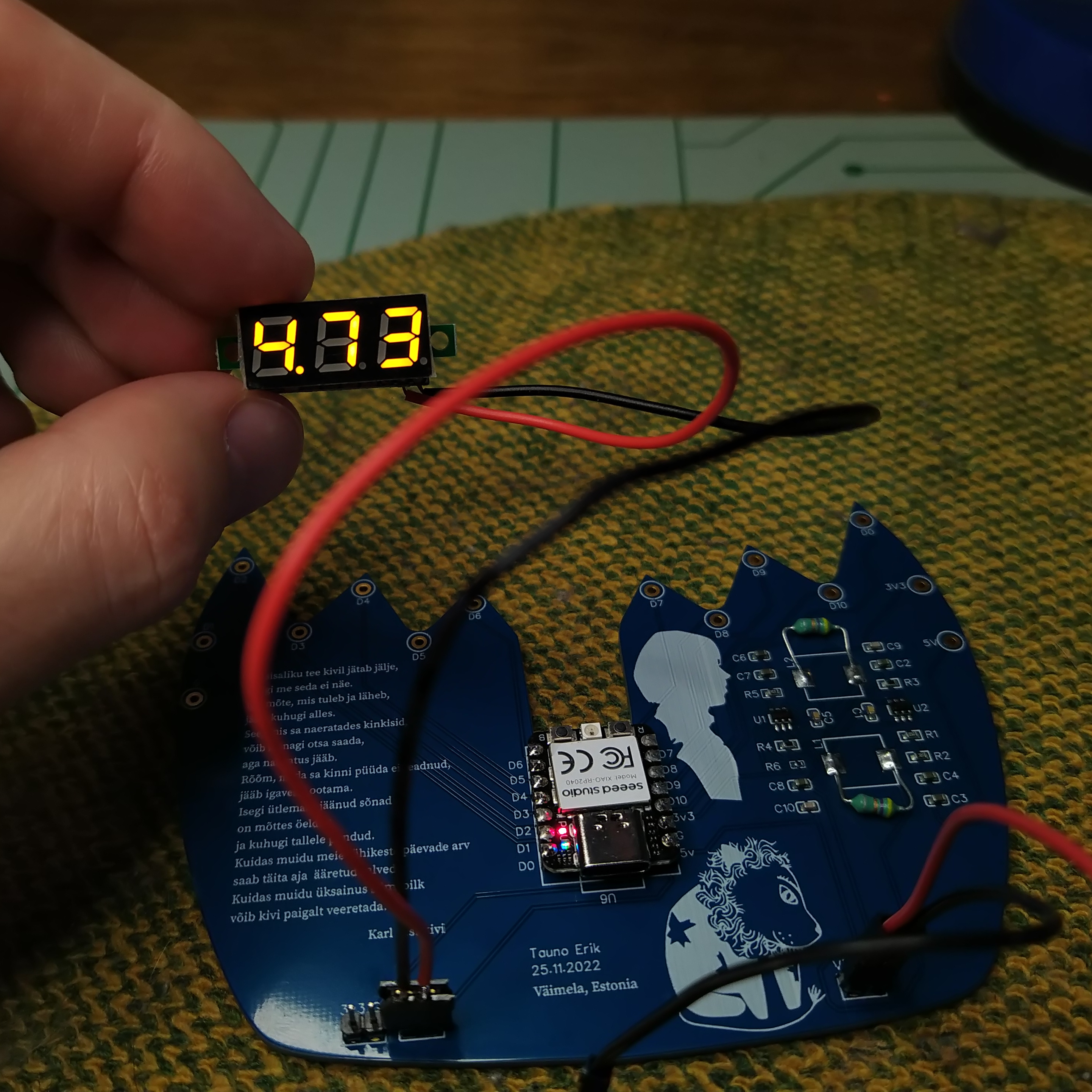
Unfortunately my design contained two mistakes:
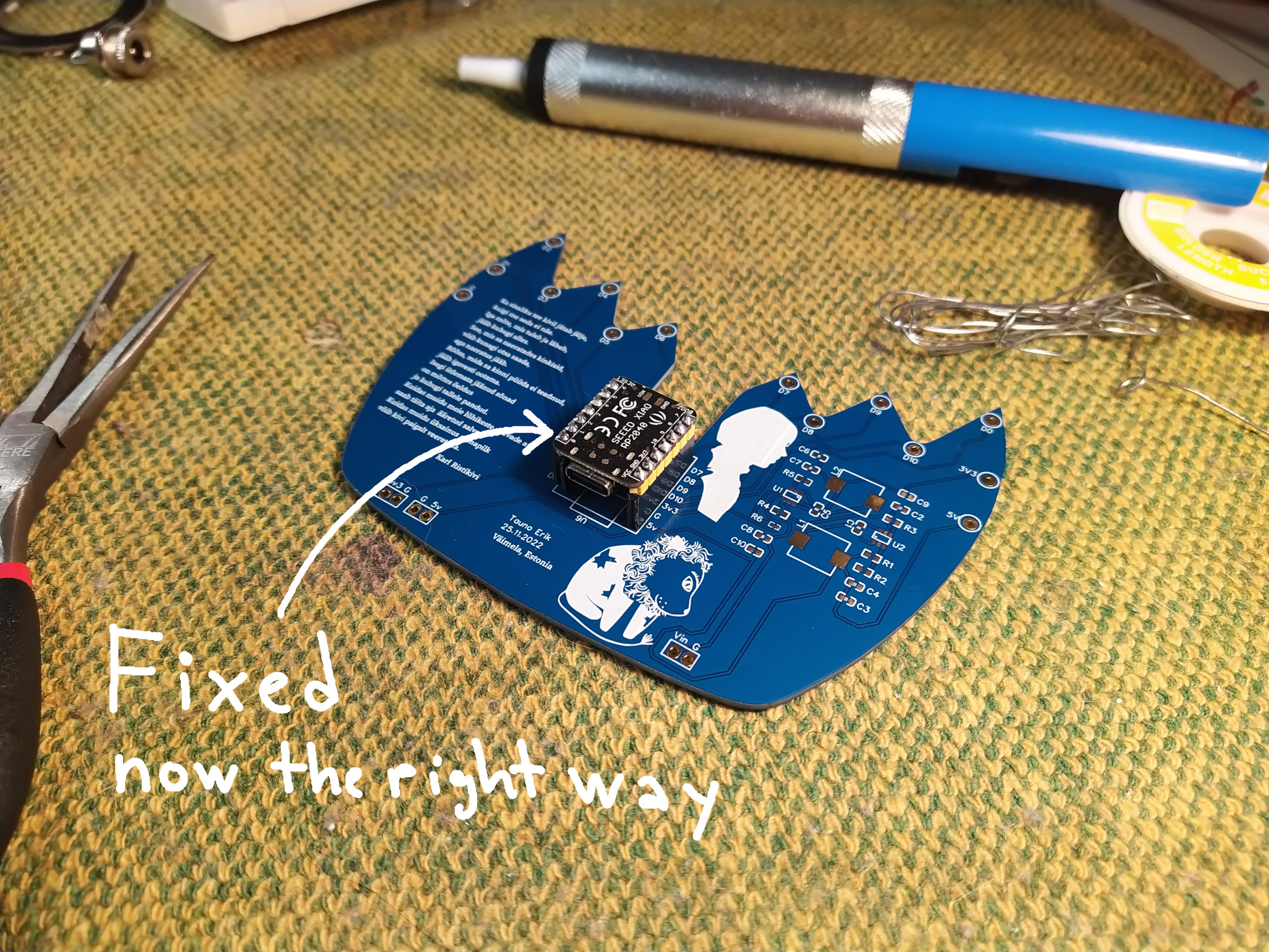
My previous post about this project.
A short animation of a dog running. Made with Blender grease pencil.
Music Daniel Johnston “Chord Organ Blues”.


My experiment was to draw animation on top of stop-motion animation. I used Blender and Davinci Resolve.

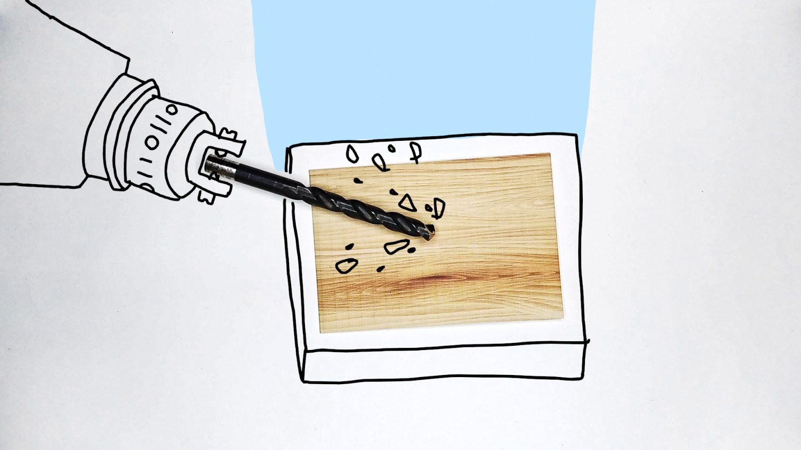
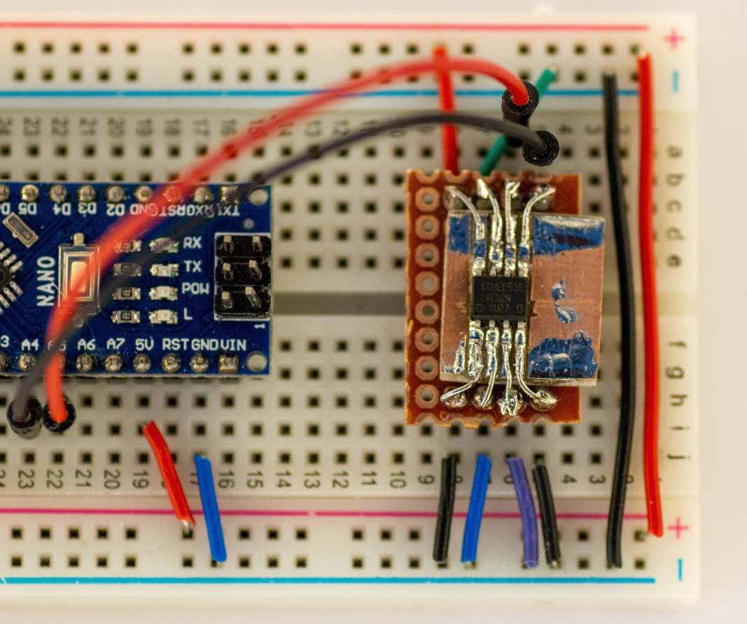
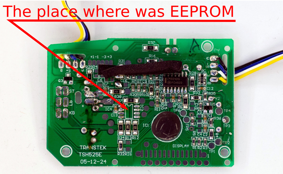
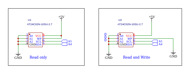
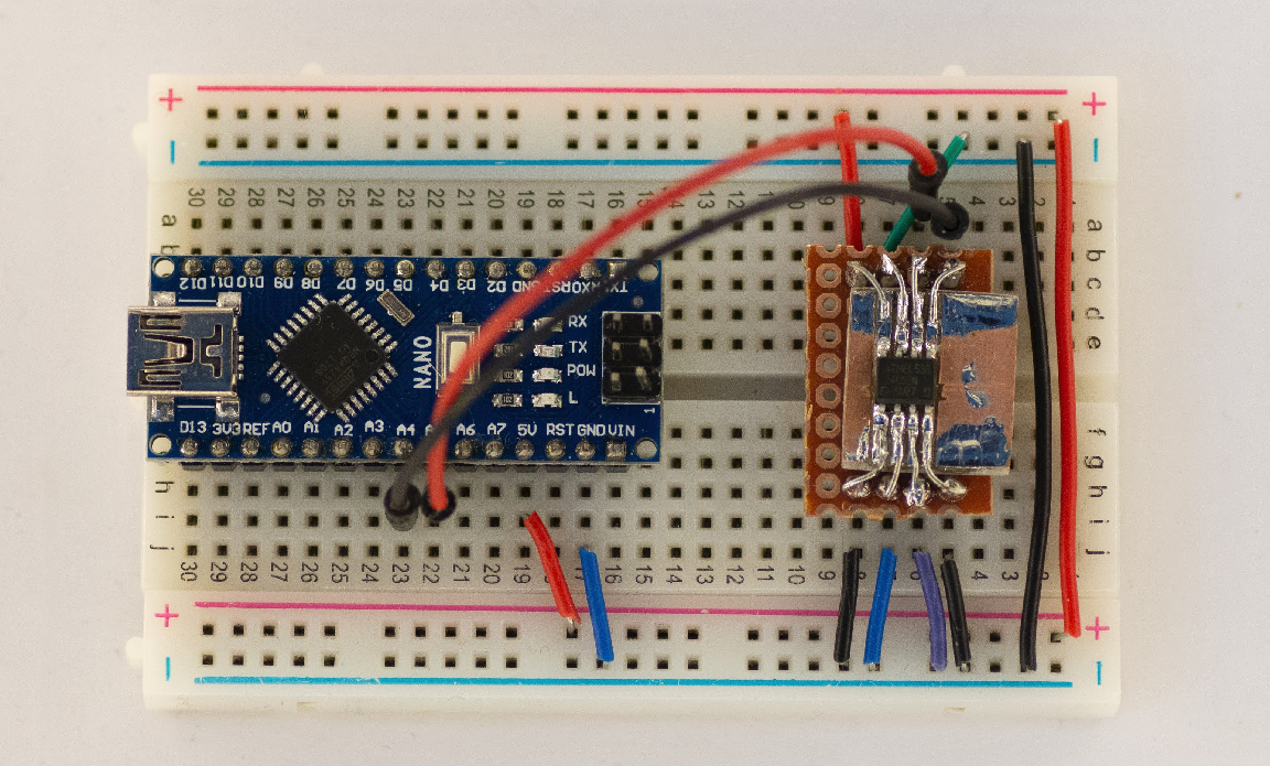
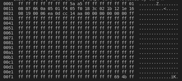
I found this tiny EEPROM from an old random board. Soldered it on copper board to use it as a through-hole component and to use on the breadboard
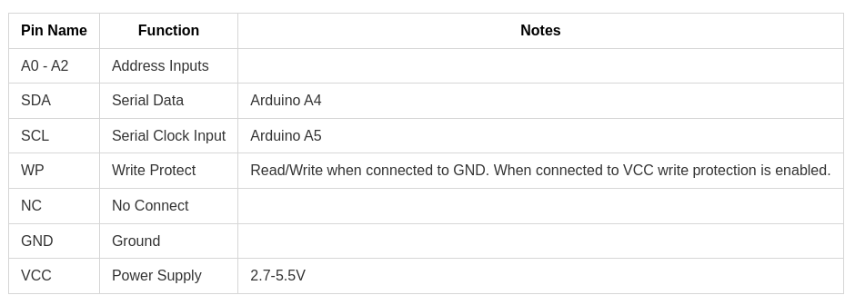
The EEPROM is 24C02N. It uses i2C to communicate and is relatively easy to read/write. I used Arduino Nano for that.

Some functions I wrote:
#include <Arduino.h>
#include <Wire.h>      // TwoWire

// read  0b10100001
// write 0b10100000
const int DEVICE_ADDR = 0b01010000; // 0 + 7bit address
const int MEM_SIZE_BYTES = 256;

/*
  Write Byte
*/
void write_byte(int word_addr, uint8_t data) {
  Wire.beginTransmission(DEVICE_ADDR);
  Wire.write(word_addr);
  Wire.write(data);
  Wire.endTransmission();
}

/*
  Write array to eepromm
*/
void write_array(uint8_t word_addr, int data[], int size) {
  Wire.beginTransmission(DEVICE_ADDR);
  Wire.write(word_addr);
  for (int i = 0; i < size; i++)
  {
    Wire.write(data[i]);
  }
  Wire.endTransmission();
}

/*
  Random Read Byte
*/
uint8_t read_byte(uint8_t word_addr) {
  uint8_t data = 0;

  Wire.beginTransmission(DEVICE_ADDR);
  Wire.write(word_addr);
  Wire.endTransmission();

  //delay(1);
  Wire.requestFrom(DEVICE_ADDR, 1); // read 1 byte
  //delay(1);
  if ( Wire.available() ) {
    data = Wire.read();
  }
  return data;
}


/*
 Read to array
*/
void read_to_array(int addr, int * array, int size ) {
  Wire.beginTransmission(DEVICE_ADDR);
  Wire.write(addr);
  Wire.endTransmission();
  delay(1);

  for (int i = 0; i < size; i++) {
    Wire.requestFrom(DEVICE_ADDR, 1); // read 1 byte
    delay(1);
    if ( Wire.available() ) {
      array[i] = Wire.read();
    }
  }
}

/*
  Print Memory content
*/
void print_ascii_table() {
  int stepp = 16;
  int line[stepp];

  for (int address = 1; address < MEM_SIZE_BYTES; address += stepp) {
    char print_addr[6];
    sprintf(print_addr, "%04x  ", address);
    Serial.print(print_addr);

    for (int byte = 0; byte < stepp; byte++)
    {
      char hex_data[4];
      line[byte] = read_byte(address+byte);
      sprintf(hex_data, "%02x ", line[byte]);
      Serial.print(hex_data);
    }
    Serial.print(" ");

    for (int ascii = 0; ascii < stepp; ascii++) {
       Serial.print((char) line[ascii]);
    }
    Serial.println();
  }
}

/*
  Print Memory content
*/
void print_char_table() {
  int stepp = 16;
  int line[stepp];

  for (int address = 1; address < MEM_SIZE_BYTES; address += stepp) {
    char print_addr[6];
    sprintf(print_addr, "%04x  ", address);
    Serial.print(print_addr);

    for (int byte = 0; byte < stepp; byte++) {
      char hex_data[4];
      line[byte] = read_byte(address+byte);
      sprintf(hex_data, "%02x ", line[byte]);
      Serial.print(hex_data);
    }
    Serial.print(" ");

    // print char
    for (int ascii = 0; ascii < stepp; ascii++) {
      if (line[ascii] < 32 || line[ascii] > 126) {
        Serial.print(".");
      } else {
        Serial.print((char) line[ascii]);
      }
    }
    Serial.println();

  }
}

void print_binary() {
/*
  for (int i = 0; i < 256; i++) // 256 bytes total
  {
    uint8_t data_byte = read_byte(i);
    Serial.print(data_byte, BIN);
    Serial.print(" ");
  }
*/
int stepp = 8;
int line[stepp];

  for (int address = 1; address < MEM_SIZE_BYTES; address += stepp) {
    char print_addr[6];
    sprintf(print_addr, "%04x  ", address);
    Serial.print(print_addr);

    for (int byte = 0; byte < stepp; byte++) {
    //char hex_data[4];
     line[byte] = read_byte(address+byte);
     // sprintf(hex_data, "%02x ", line[byte]);
     // Serial.print(hex_data);

      Serial.print(line[byte], BIN);
      Serial.print(" ");
    }

    // print char
    for (int ascii = 0; ascii < stepp; ascii++) {
      if (line[ascii] < 32 || line[ascii] > 126) {
        Serial.print(".");
      } else {
        Serial.print((char) line[ascii]);
      }
    }
    Serial.println();

  }

}

void setup() {
  Serial.begin(115200);
  Wire.begin();
  //write_byte(254, 105);

  //print_ascii_table();
  print_char_table();
  //print_binary();
  /*
  int my_data[10] = {};

  write_array(1, my_data, 10);

  int data[10];
  read_to_array(1, data, 10);

  for (int i = 0; i < 10; i++)
  {
    Serial.print(data[i]);
  }
  */


}

void loop() {

}
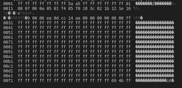
EEPROM memory content:
I animated one of my drawings.
Music: True Love Will Find You in the End – Daniel Johnston
My original image:

This is my idea to make face shaped circuit board. It will use the Seeed Grove Vision AI Module. The plan is to make an electronic sculpture that uses machine vision. And the MCU board is a tiny but powerful Seeed XIAO RP2040 that uses the same microcontroller as Raspberry Pi Pico.